Page 1404 of 2053
SSANGYONG MY2002
5D2-4 TRANSFER CASE (PART TIME - 4408)
Power Flow
TCCU
Switch Transfer
2H, 4H
↔ 4L
Rear Propeller Shaft
Rear Wheel
Front Axle
Transfer
Locking Hub Solenoid
Locking Hub
OperationVacuum System Operation
Front Propeller Shaft
Front Wheel
Rear Axle
Page 1413 of 2053
TRANSFER CASE (PART TIME - 4408) 5D2-13
SSANGYONG MY2002
Diagnostic Table
Connect a service connector. If turn the ignition switch
“ON” “4WD CHECK” indicator light will come on for
0.6 second and turn off for 3 seconds and then display
a defective code 3 times continuously.
4WD CHECK
Light
ON
OFF
4WD CHECK
Light
ON
OFF
4WD CHECK
Light
ON
OFF
4WD CHECK
Light
ON
OFF
4WD CHECK
Light
ON
OFFTCCU
Shift Motor
Synchronizer Clutch
Speed Sensor
Locking Hub Solenoid Defective Code No.
1
2
3
4
5
Malfunctioning Part
KAA5D140
KAA5D150
KAA5D160
KAA5D170
KAA5D180
Page 1418 of 2053

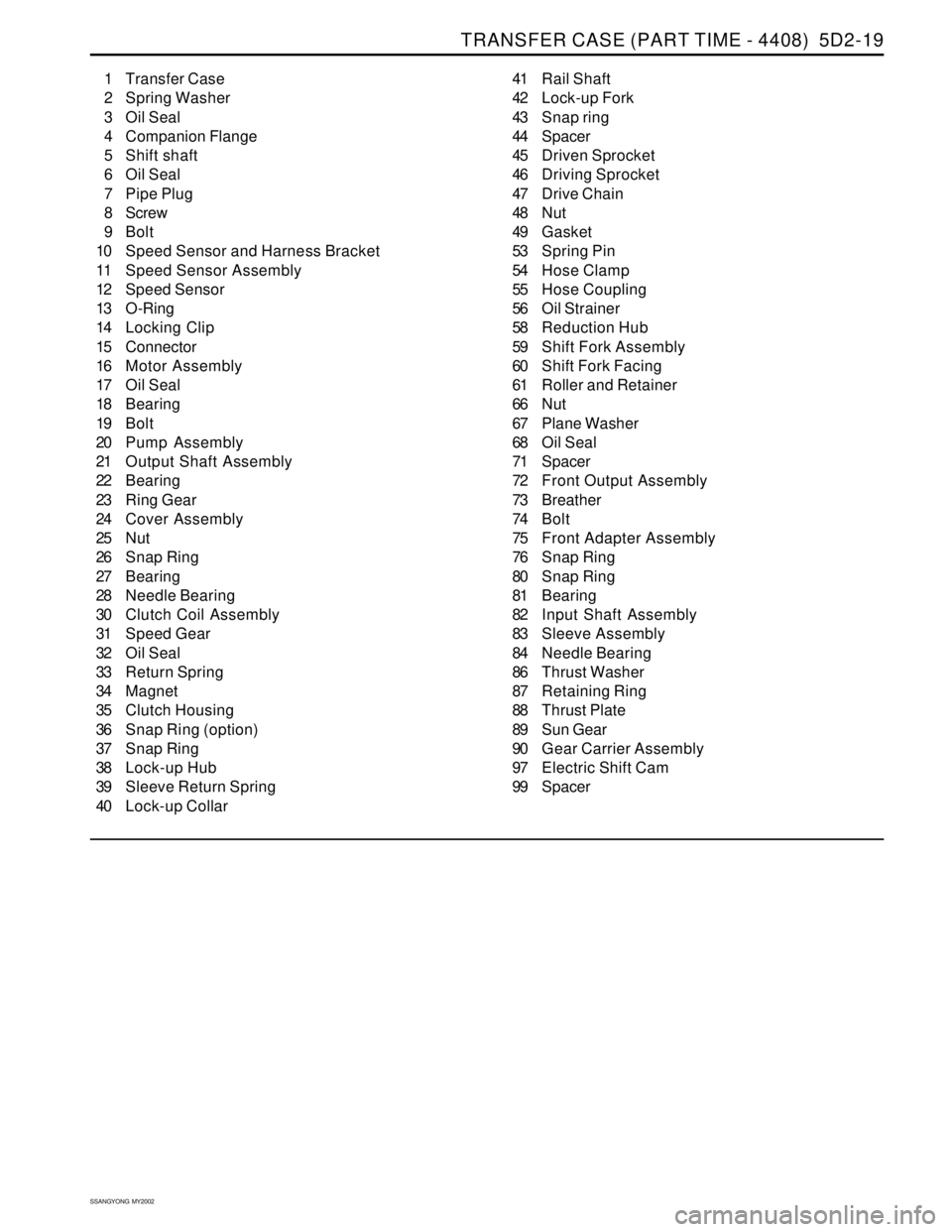
TRANSFER CASE (PART TIME - 4408) 5D2-19
SSANGYONG MY2002
1 Transfer Case
2 Spring Washer
3 Oil Seal
4 Companion Flange
5 Shift shaft
6 Oil Seal
7 Pipe Plug
8 Screw
9 Bolt
10 Speed Sensor and Harness Bracket
11 Speed Sensor Assembly
12 Speed Sensor
13 O-Ring
14 Locking Clip
15 Connector
16 Motor Assembly
17 Oil Seal
18 Bearing
19 Bolt
20 Pump Assembly
21 Output Shaft Assembly
22 Bearing
23 Ring Gear
24 Cover Assembly
25 Nut
26 Snap Ring
27 Bearing
28 Needle Bearing
30 Clutch Coil Assembly
31 Speed Gear
32 Oil Seal
33 Return Spring
34 Magnet
35 Clutch Housing
36 Snap Ring (option)
37 Snap Ring
38 Lock-up Hub
39 Sleeve Return Spring
40 Lock-up Collar41 Rail Shaft
42 Lock-up Fork
43 Snap ring
44 Spacer
45 Driven Sprocket
46 Driving Sprocket
47 Drive Chain
48 Nut
49 Gasket
53 Spring Pin
54 Hose Clamp
55 Hose Coupling
56 Oil Strainer
58 Reduction Hub
59 Shift Fork Assembly
60 Shift Fork Facing
61 Roller and Retainer
66 Nut
67 Plane Washer
68 Oil Seal
71 Spacer
72 Front Output Assembly
73 Breather
74 Bolt
75 Front Adapter Assembly
76 Snap Ring
80 Snap Ring
81 Bearing
82 Input Shaft Assembly
83 Sleeve Assembly
84 Needle Bearing
86 Thrust Washer
87 Retaining Ring
88 Thrust Plate
89 Sun Gear
90 Gear Carrier Assembly
97 Electric Shift Cam
99 Spacer
Page 1420 of 2053

TRANSFER CASE (PART TIME - 4408) 5D2-21
SSANGYONG MY2002
KAA5D240
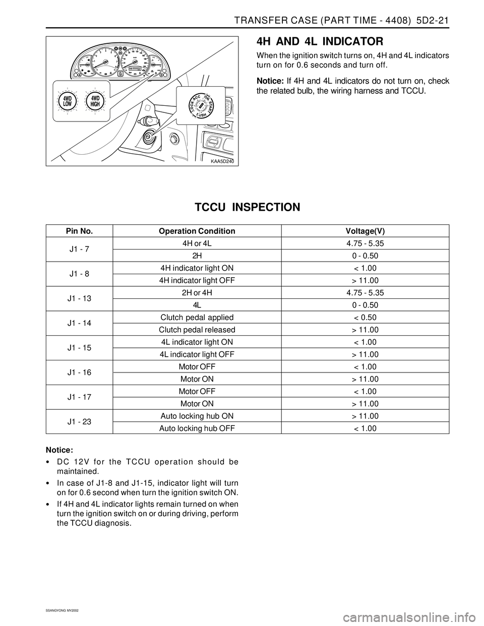
4H AND 4L INDICATOR
When the ignition switch turns on, 4H and 4L indicators
turn on for 0.6 seconds and turn off.
Notice: If 4H and 4L indicators do not turn on, check
the related bulb, the wiring harness and TCCU.
J1 - 7
J1 - 8
J1 - 13
J1 - 14
J1 - 15
J1 - 16
J1 - 17
J1 - 234H or 4L
2H
4H indicator light ON
4H indicator light OFF
2H or 4H
4L
Clutch pedal applied
Clutch pedal released
4L indicator light ON
4L indicator light OFF
Motor OFF
Motor ON
Motor OFF
Motor ON
Auto locking hub ON
Auto locking hub OFF
TCCU INSPECTION
4.75 - 5.35
0 - 0.50
< 1.00
> 11.00
4.75 - 5.35
0 - 0.50
< 0.50
> 11.00
< 1.00
> 11.00
< 1.00
> 11.00
< 1.00
> 11.00
> 11.00
< 1.00
Pin No. Voltage(V)Operation Condition
Notice:
DC 12V for the TCCU operation should be
maintained.
In case of J1-8 and J1-15, indicator light will turn
on for 0.6 second when turn the ignition switch ON.
If 4H and 4L indicator lights remain turned on when
turn the ignition switch on or during driving, perform
the TCCU diagnosis.
Page 1425 of 2053
TRANSFER CASE (PART TIME - 4408) 5D2-27
SSANGYONG MY2002
KAA5D460
KAA5D470
Transfer Case Assembly
1. Separate the shift motor shaft cam assembly and
the spring (1).
KAA5D480
KAA5D490
2. Remove the clutch housing assembly from the
output shaft.
Clutch Housing Component
(1) Retaining Ring
(2) Shift collar Hub
(3) Clutch Housing
Remove the shift cam from the shaft.
Fix the shaft at the vise with the cam removed
and remove the torsion bar using a driver.
3. Remove the 2WD/4WD lock up assembly, the lock
up fork and rail shaft from the output shaft.
Page 1426 of 2053
SSANGYONG MY2002
5D2-28 TRANSFER CASE (PART TIME - 4408)
KAA5D500
KAA5D510
KAA5D520
KAA5D530
2WD/4WD Lock Up Assembly Component.
(37) Snap Ring
(38) Lock up Hub
(39) Return Spring
(40) Lock up Collar
4. Remove the snap ring from the front output driven
sprocket and separate the snap ring and the
spacer.
5. Remove the driving sprocket, the driven sprocket
and the driving chain from the front/rear output
shaft.
6. Remove the oil pump assembly and the magnetic
from the output shaft.
Page 1439 of 2053
SSANGYONG MY2002
5D2-40 TRANSFER CASE (PART TIME - 4408)
KAA5D880
KAA5D890
Lockup Shift
1. Install the lockup hub and return spring to the
lockup collar and insert the snap ring.
2. Install the rail shaft through reduction shift fork
assembly previously installed and into the blind
hole in case.
3. Engage the lockup fork into the 2WD/4WD groove
and check operation.
4. Install the shift collar hub to the output shaft spline.
5. Install the previously assembled electric shift cam
and assemble the clutch housing as follows.
Rotate the shift cam assembly to right so that
the end of the torsion spring contacts with
reduction shift fork side.
Holding the rail shaft, lift up the fork assembly
slightly.
Adjust electric shift cam assembly so that the
roller on reduction shift fork assembly is in
groove in shift cam and button on lockup fork
is on cam end.
Install the clutch housing over shift collar hub
and insert the retaining ring into the clutch collar
hub groove.
Page 1441 of 2053
SSANGYONG MY2002
5D2-42 TRANSFER CASE (PART TIME - 4408)
5. Tighten 9 bolts positioning identification tag and
wiring clip.
Installation Notice
6. Install the speed gear over output shaft spline in
the cover assembly.
7. Press the new oil seal into the cover assembly.
Tightening Torque28 - 40 Nm
(21 - 30 lb-ft)
KAA5D920
KAA5D930
KAA5D940
External Electric Shift
1. Align the motor with shift shaft and position the
motor assembly onto the cover.
2. Install the motor to the shift shaft and contact
cover and rotate the motor clockwise direction to
check correct engagement.
3. Insert the O-ring on the speed sensor assembly
to the cover.
4. Install the bracket to the motor assembly and
tighten 3 bolts.
Installation Notice
Tightening Torque8 - 11 Nm
(71 - 97 lb-in)