Page 397 of 2053

1D2 -- 2 M161 ENGINE COOLING
D AEW OO M Y_2000
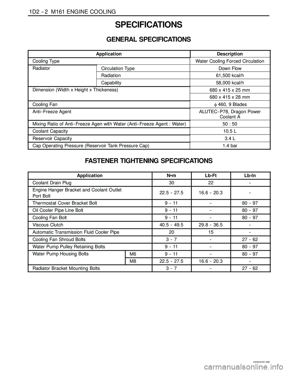
SPECIFICATIONS
GENERAL SPECIFICATIONS
ApplicationDescription
Cooling TypeWater Cooling Forced Circulation
RadiatorCirculation TypeDown Flow
Radiation61,500 kcal/h
Capability58,000 kcal/h
Dimension (Width x Height x Thickeness)680 x 415 x 25 mm(g)
680 x 415 x 28 mm
Cooling Fanφ460, 9 Blades
Anti-- Freeze AgentALUTEC-- P78, Dragon Power
Coolant A
Mixing Ratio of Anti-- Freeze Agen with Water (Anti-- Freeze Agent : Water)50 : 50
Coolant Capacity10.5 L
Reservoir Capacity3.4 L
Cap Operating Pressure (Reservoir Tank Pressure Cap)1.4 bar
FASTENER TIGHTENING SPECIFICATIONS
ApplicationNSmLb-FtLb-In
Coolant Drain Plug3022--
Engine Hanger Bracket and Coolant Outlet
Port Bolt22.5 -- 27.516.6 -- 20.3--
Thermostat Cover Bracket Bolt9--11--80 -- 97
Oil Cooler Pipe Line Bolt9--11--80 -- 97
Cooling Fan Bolt9--11--80 -- 97
Viscous Clutch40.5 -- 49.529.8 -- 36.5--
Automatic Transmission Fluid Cooler Pipe2015--
Cooling Fan Shroud Bolts3--7--27 -- 62
Water Pump Pulley Retaining Bolts9--11--80 -- 97
Water Pump Housing BoltsM69--11--80 -- 97pg
M822.5 -- 27.516.6 -- 20.3--
Radiator Bracket Mounting Bolts3--7--27 -- 62
Page 459 of 2053
M161 ENGINE CONTROLS 1F2 -- 41
D AEW OO M Y_2000
Battery Voltage Correction Mode
When battery voltage is low, the ECM can compensate for a weak spark delivered by the ignition module by using the
following methods:
DIncreasing the fuel injector pulse width.
DIncreasing the idle speed rpm.
DIncreasing the ignition dwell time.
Fuel Cut- Off Mode
No fuel is delivered by the fuel injectors when the ignition is off. This prevents dieseling or engine run -- on. Also, the fuel
is not delivered if there are no reference pulses received from the CKP sensor. This prevents flooding.
Page 467 of 2053
M161 ENGINE CONTROLS 1F2 -- 49
D AEW OO M Y_2000
Injector Pulse Width Inspection
1. Turn the ignition switch OFF.
2. Install the scan tool.
3. Turn the ignition switch ON.
4. Monitor the “INJECTION TIME” with a scan tool.
Cranking
8.0 ms
Engine Idle3~5ms
Wide Open Throttle (WOT)14 ms
Page 635 of 2053

1B3 -- 86 OM600 ENGINE MECHANICAL
D AEW OO M Y_2000
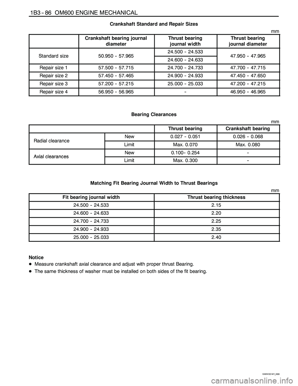
Crankshaft Standard and Repair Sizes
mm
Crankshaft bearing journal
diameterThrust bearing
journal widthThrust bearing
journal diameter
Standardsize509505796524.500 -- 24.5334795047965Standardsize50.950 -- 57.96524.600 -- 24.63347.950 -- 47.965
Repair size 157.500 -- 57.71524.700 -- 24.73347.700 -- 47.715
Repair size 257.450 -- 57.46524.900 -- 24.93347.450 -- 47.650
Repair size 357.200 -- 57.21525.000 -- 25.03347.200 -- 47.215
Repair size 456.950 -- 56.965--46.950 -- 46.965
Bearing Clearances
mm
Thrust bearingCrankshaft bearing
RadialclearanceNew0.027 -- 0.0510.026 -- 0.068RadialclearanceLimitMax. 0.070Max. 0.080
AxialclearancesNew0.100-- 0.254--AxialclearancesLimitMax. 0.300--
Matching Fit Bearing Journal Width to Thrust Bearings
mm
Fit bearing journal widthThrust bearing thickness
24.500 -- 24.5332.15
24.600 -- 24.6332.20
24.700 -- 24.7332.25
24.900 -- 24.9332.35
25.000 -- 25.0332.40
Notice
DMeasure crankshaft axial clearance and adjust with proper thrust Bearing.
DThe same thickness of washer must be installed on both sides of the fit bearing.
Page 639 of 2053
1B3 -- 90 OM600 ENGINE MECHANICAL
D AEW OO M Y_2000
15. Measure radial clearance of crankshaft bearing (G).
Clearance ’G’0.027 -- 0.051mm
Notice
If ’G’ is out of standard, replace the bearing shells
and adjust the radial clearance of crankshaft bear-
ing.
Example) Measured value ’E’ = 57.700mm
Measured value ’F’ = 57.659mm
——————————————
Clearance ’G’ = 0.041mm
16. Remove the crankshaft bearing cap.
17. Measure width of thrust bearing journal (H) and ad-
just with proper thrust bearings (see table).
Notice
The same thickness of thrust washers should be
installed on both sides of the thrust bearing.
18. Coat the upper thrust bearing (4) with oil and insert
into the crankcase so that the oil grooves are facing
the crank webs (arrow).
19. Coat the lower thrust bearing (7) with oil and insert
into the crankshaft bearing cap so that the oil
grooves are facing the crank webs (arrow).
Notice
The retaining lugs should be positioned in the
grooves (arrow).
Page 682 of 2053

OM600 ENGINE MECHANICAL 1B3 -- 133
D AEW OO M Y_2000
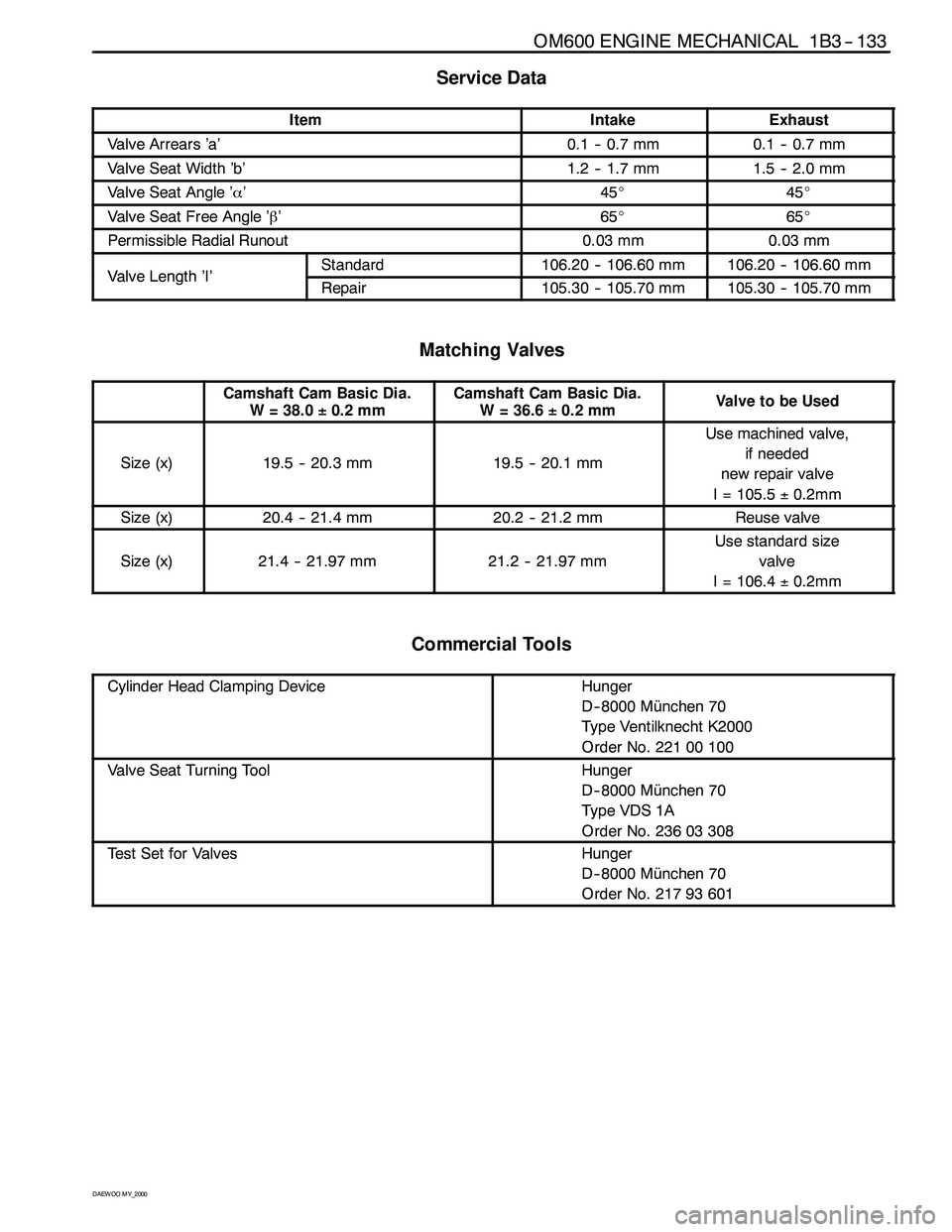
Service Data
ItemIntakeExhaust
Valve Arrears ’a’0.1 -- 0.7 mm0.1 -- 0.7 mm
Valve Seat Width ’b’1.2 -- 1.7 mm1.5 -- 2.0 mm
Valve Seat Angle ’α’45_45_
Valve Seat Free Angle ’β’65_65_
Permissible Radial Runout0.03 mm0.03 mm
ValveLength’I’Standard106.20 -- 106.60 mm106.20 -- 106.60 mmValveLength’I’Repair105.30 -- 105.70 mm105.30 -- 105.70 mm
Matching Valves
Camshaft Cam Basic Dia.
W = 38.0±0.2 mmCamshaft Cam Basic Dia.
W=36.6±0.2 mmValvetobeUsed
Size (x)19.5 -- 20.3 mm19.5 -- 20.1 mm
Use machined valve,
if needed
new repair valve
I = 105.5±0.2mm
Size (x)20.4 -- 21.4 mm20.2 -- 21.2 mmReuse valve
Size (x)21.4 -- 21.97 mm21.2 -- 21.97 mm
Use standard size
valve
I = 106.4±0.2mm
Commercial Tools
Cylinder Head Clamping DeviceHunger
D-- 8000 München 70
Type Ventilknecht K2000
Order No. 221 00 100
Valve Seat Turning ToolHunger
D-- 8000 München 70
Ty p e VDS 1 A
Order No. 236 03 308
Test Set for ValvesHunger
D-- 8000 München 70
Order No. 217 93 601
Page 683 of 2053
1B3 -- 134 OM600 ENGINE MECHANICAL
D AEW OO M Y_2000
Machining Procedure
Valve machining is required :
-- When the valve is leaking.
-- When replacing the valve.
-- When replacing the valve guide.
-- When replacing the valve seat or valve seat ring.
1. Machine the valve seat (a=45_).
2. Measure valve seat width ’b’.
Va lv e s e a tIntake1.2 -- 1.7 mmValveseat
width ’b’Exhaust1.5 -- 2.0 mm
3. If the specification is exceeded, the valve seat width
has to be corrected at the lower free angle of
’β’=65�.
4. Measure radial runout.
RunoutMax. 0.03mm
Page 858 of 2053

SSANGYONG MY2002
2E-4 TIRE AND WHEELS
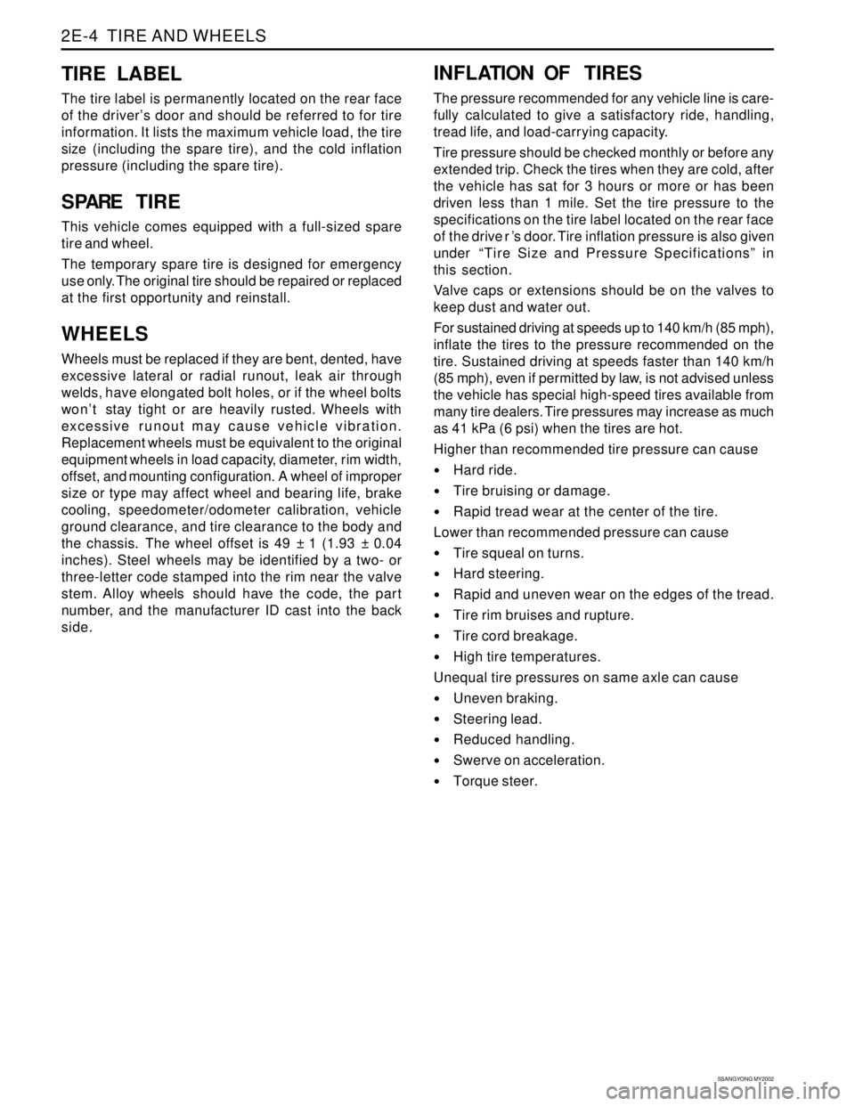
TIRE LABEL
The tire label is permanently located on the rear face
of the driver’s door and should be referred to for tire
information. It lists the maximum vehicle load, the tire
size (including the spare tire), and the cold inflation
pressure (including the spare tire).
S PARE TIRE
This vehicle comes equipped with a full-sized spare
tire and wheel.
The temporary spare tire is designed for emergency
use only. The original tire should be repaired or replaced
at the first opportunity and reinstall.
WHEELS
Wheels must be replaced if they are bent, dented, have
excessive lateral or radial runout, leak air through
welds, have elongated bolt holes, or if the wheel bolts
won’t stay tight or are heavily rusted. Wheels with
excessive runout may cause vehicle vibration.
Replacement wheels must be equivalent to the original
equipment wheels in load capacity, diameter, rim width,
offset, and mounting configuration. A wheel of improper
size or type may affect wheel and bearing life, brake
cooling, speedometer/odometer calibration, vehicle
ground clearance, and tire clearance to the body and
the chassis. The wheel offset is 49 ± 1 (1.93 ± 0.04
inches). Steel wheels may be identified by a two- or
three-letter code stamped into the rim near the valve
stem. Alloy wheels should have the code, the part
number, and the manufacturer ID cast into the back
side.
INFLATION OF TIRES
The pressure recommended for any vehicle line is care-
fully calculated to give a satisfactory ride, handling,
tread life, and load-carrying capacity.
Tire pressure should be checked monthly or before any
extended trip. Check the tires when they are cold, after
the vehicle has sat for 3 hours or more or has been
driven less than 1 mile. Set the tire pressure to the
specifications on the tire label located on the rear face
of the drive r ’s door. Tire inflation pressure is also given
under “Tire Size and Pressure Specifications” in
this section.
Valve caps or extensions should be on the valves to
keep dust and water out.
For sustained driving at speeds up to 140 km/h (85 mph),
inflate the tires to the pressure recommended on the
tire. Sustained driving at speeds faster than 140 km/h
(85 mph), even if permitted by law, is not advised unless
the vehicle has special high-speed tires available from
many tire dealers. Tire pressures may increase as much
as 41 kPa (6 psi) when the tires are hot.
Higher than recommended tire pressure can cause
Hard ride.
Tire bruising or damage.
Rapid tread wear at the center of the tire.
Lower than recommended pressure can cause
Tire squeal on turns.
Hard steering.
Rapid and uneven wear on the edges of the tread.
Tire rim bruises and rupture.
Tire cord breakage.
High tire temperatures.
Unequal tire pressures on same axle can cause
Uneven braking.
Steering lead.
Reduced handling.
Swerve on acceleration.
Torque steer.