1997 SSANGYONG KORANDO clock
[x] Cancel search: clockPage 765 of 2053

OM600 ENGINE CONTROLS 1F3 -- 3
D AEW OO M Y_2000
FUEL INJECTION PUMP CODING
Model Code
OM661 LA EnginePES 4M 55C 320 RS 167
OM662 LA EnginePES 5M 55C 320 RS 168
Fuel Injection Pump Code
Example) PES 5M 55C 320 RS 168
PPump
E Self -- Driven
S End Flange Mounting
5 Number of Cylinders (5EA)
MPumpSize
55 Element Diameter
C Modification Letter
320 Assembly Number
R Direction of Rotation (clockwise)
S188 Special Version
RSF Governor
R Governor
S Coil Spring
F Drive Governor
Component Location
1. Fuel Injection Pump
2. Vacuum Unit (Stop Unit)
3. Control Lever
4. PLA Vacuum Unit (Idle Speed Adjustment)
5. Governor
6. Fuel Pump
Page 773 of 2053

1F3 -- 16 OM600 ENGINE CONTROLS
D AEW OO M Y_2000
5. Ensure not to damage the idle spring in the governor
and adjust idle speed by turning the PLA unit (5)
slowly.
ClockwiseRPM Decrease
CounterclockwiseRPM Increase
Notice
Do not rotate the PLA unit over 1/2 turn from the
position marking. If do, idle spring in the governor
will be severely damaged.
6. After adjustment, tighten the locking nut and place
the position marking with different color of paint.
Notice
If there are no changes in idle speed with PLA unit
adjustment, perform the service at a BOSCH Ser-
vice Center.
7. Connect the vacuum pump to the PLA vacuum unit
and build up vacuum approx. 500mbar. If engine
rpm increases by approx. 100rpm, It is normal.
Vacuum Pump 001 589 73 21 00
8. Connect the vacuum line (4).
9. Switch on all ancillaries and check the idle speed.
Page 1117 of 2053
AUTOMATIC TRANSMISSION 5A-23
SSANGYONG MY2002
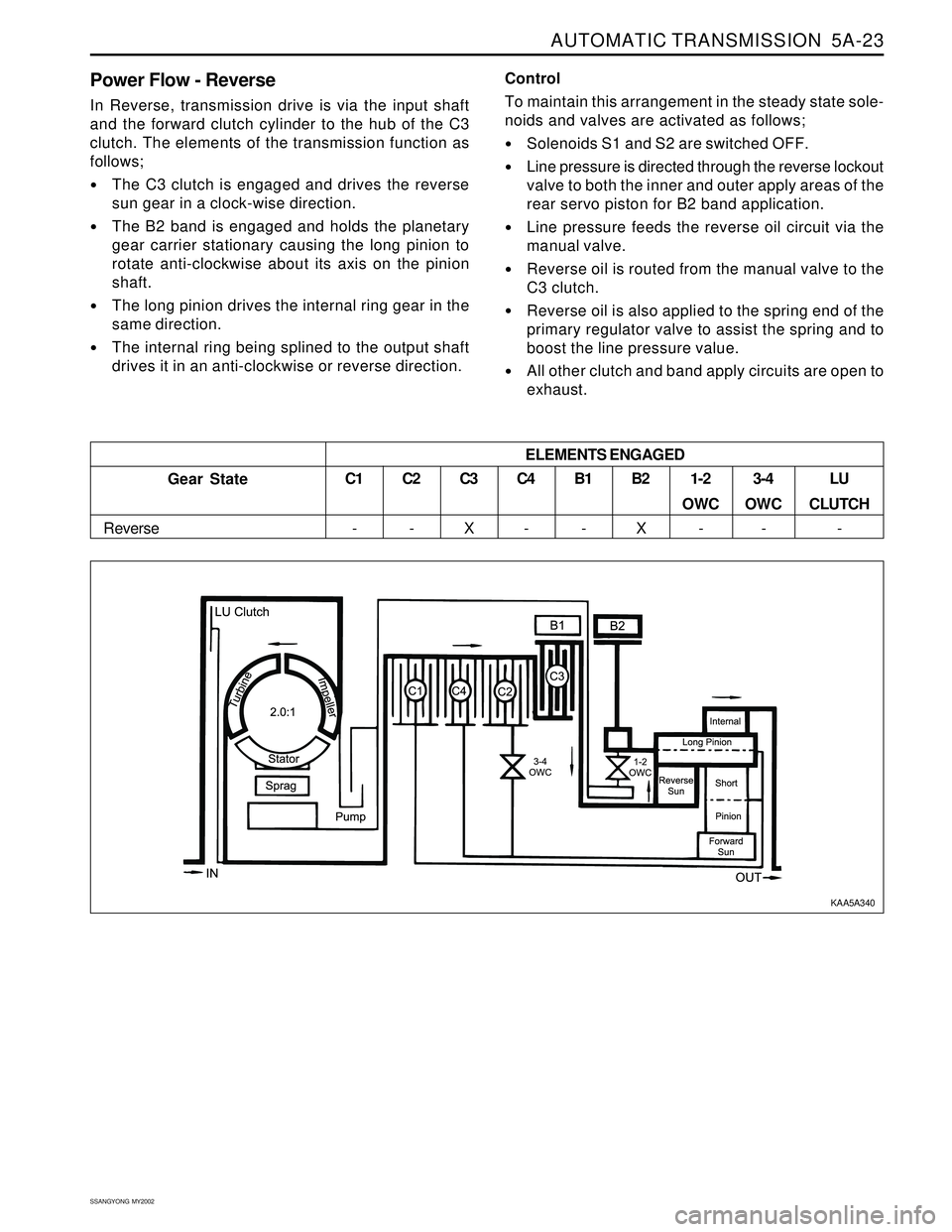
Power Flow - Reverse
In Reverse, transmission drive is via the input shaft
and the forward clutch cylinder to the hub of the C3
clutch. The elements of the transmission function as
follows;
The C3 clutch is engaged and drives the reverse
sun gear in a clock-wise direction.
The B2 band is engaged and holds the planetary
gear carrier stationary causing the long pinion to
rotate anti-clockwise about its axis on the pinion
shaft.
The long pinion drives the internal ring gear in the
same direction.
The internal ring being splined to the output shaft
drives it in an anti-clockwise or reverse direction.Control
To maintain this arrangement in the steady state sole-
noids and valves are activated as follows;
Solenoids S1 and S2 are switched OFF.
Line pressure is directed through the reverse lockout
valve to both the inner and outer apply areas of the
rear servo piston for B2 band application.
Line pressure feeds the reverse oil circuit via the
manual valve.
Reverse oil is routed from the manual valve to the
C3 clutch.
Reverse oil is also applied to the spring end of the
primary regulator valve to assist the spring and to
boost the line pressure value.
All other clutch and band apply circuits are open to
exhaust.
C3
X
Gear State
ReverseC1
-C2
-C4
-B1
-B2
X1-2
OWC
-3-4
OWC
-LU
CLUTCH
- ELEMENTS ENGAGED
KAA5A340
Page 1119 of 2053
AUTOMATIC TRANSMISSION 5A-25
SSANGYONG MY2002
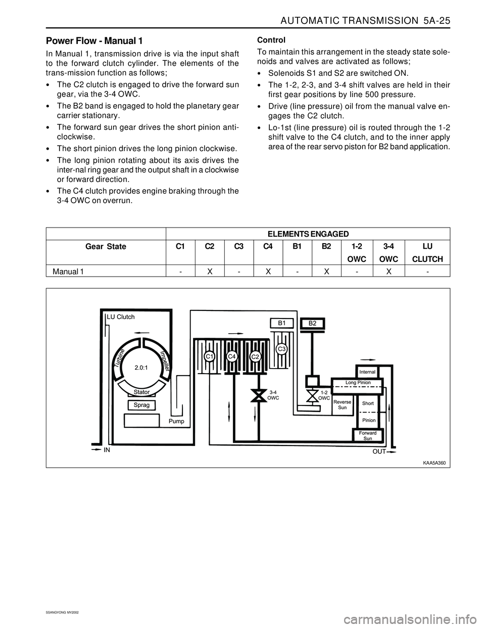
Power Flow - Manual 1
In Manual 1, transmission drive is via the input shaft
to the forward clutch cylinder. The elements of the
trans-mission function as follows;
The C2 clutch is engaged to drive the forward sun
gear, via the 3-4 OWC.
The B2 band is engaged to hold the planetary gear
carrier stationary.
The forward sun gear drives the short pinion anti-
clockwise.
The short pinion drives the long pinion clockwise.
The long pinion rotating about its axis drives the
inter-nal ring gear and the output shaft in a clockwise
or forward direction.
The C4 clutch provides engine braking through the
3-4 OWC on overrun.Control
To maintain this arrangement in the steady state sole-
noids and valves are activated as follows;
Solenoids S1 and S2 are switched ON.
The 1-2, 2-3, and 3-4 shift valves are held in their
first gear positions by line 500 pressure.
Drive (line pressure) oil from the manual valve en-
gages the C2 clutch.
Lo-1st (line pressure) oil is routed through the 1-2
shift valve to the C4 clutch, and to the inner apply
area of the rear servo piston for B2 band application.
ELEMENTS ENGAGED
Gear State
Manual 1C1
-C2
XC3
-C4
XB1
-B2
X1-2
OWC
-3-4
OWC
XLU
CLUTCH
-
KAA5A360
Page 1121 of 2053
AUTOMATIC TRANSMISSION 5A-27
SSANGYONG MY2002
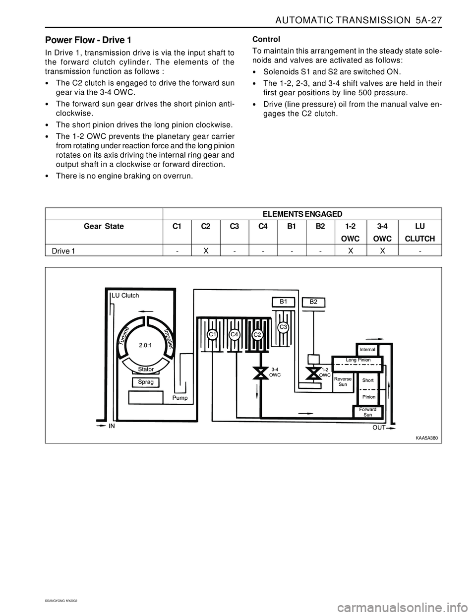
Power Flow - Drive 1
In Drive 1, transmission drive is via the input shaft to
the forward clutch cylinder. The elements of the
transmission function as follows :
The C2 clutch is engaged to drive the forward sun
gear via the 3-4 OWC.
The forward sun gear drives the short pinion anti-
clockwise.
The short pinion drives the long pinion clockwise.
The 1-2 OWC prevents the planetary gear carrier
from rotating under reaction force and the long pinion
rotates on its axis driving the internal ring gear and
output shaft in a clockwise or forward direction.
There is no engine braking on overrun.Control
To maintain this arrangement in the steady state sole-
noids and valves are activated as follows:
Solenoids S1 and S2 are switched ON.
The 1-2, 2-3, and 3-4 shift valves are held in their
first gear positions by line 500 pressure.
Drive (line pressure) oil from the manual valve en-
gages the C2 clutch.
Gear State
Drive 1C1
-
C2
XC3
-C4
-B1
-B2
-1-2
OWC
X3-4
OWC
XLU
CLUTCH
- ELEMENTS ENGAGED
KAA5A380
Page 1123 of 2053
AUTOMATIC TRANSMISSION 5A-29
SSANGYONG MY2002
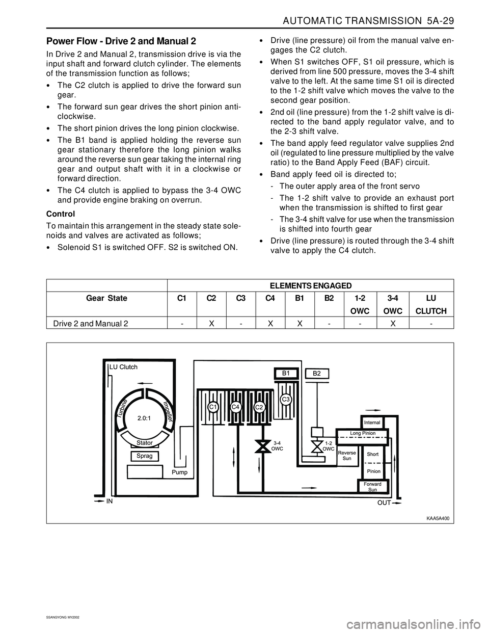
Power Flow - Drive 2 and Manual 2
In Drive 2 and Manual 2, transmission drive is via the
input shaft and forward clutch cylinder. The elements
of the transmission function as follows;
The C2 clutch is applied to drive the forward sun
gear.
The forward sun gear drives the short pinion anti-
clockwise.
The short pinion drives the long pinion clockwise.
The B1 band is applied holding the reverse sun
gear stationary therefore the long pinion walks
around the reverse sun gear taking the internal ring
gear and output shaft with it in a clockwise or
forward direction.
The C4 clutch is applied to bypass the 3-4 OWC
and provide engine braking on overrun.
Control
To maintain this arrangement in the steady state sole-
noids and valves are activated as follows;
Solenoid S1 is switched OFF. S2 is switched ON.
Drive (line pressure) oil from the manual valve en-
gages the C2 clutch.
When S1 switches OFF, S1 oil pressure, which is
derived from line 500 pressure, moves the 3-4 shift
valve to the left. At the same time S1 oil is directed
to the 1-2 shift valve which moves the valve to the
second gear position.
2nd oil (line pressure) from the 1-2 shift valve is di-
rected to the band apply regulator valve, and to
the 2-3 shift valve.
The band apply feed regulator valve supplies 2nd
oil (regulated to line pressure multiplied by the valve
ratio) to the Band Apply Feed (BAF) circuit.
Band apply feed oil is directed to;
- The outer apply area of the front servo
- The 1-2 shift valve to provide an exhaust port
when the transmission is shifted to first gear
- The 3-4 shift valve for use when the transmission
is shifted into fourth gear
Drive (line pressure) is routed through the 3-4 shift
valve to apply the C4 clutch.
Gear State
Drive 2 and Manual 2ELEMENTS ENGAGEDC1
-C2
XC3
-C4
XB1
XB2
-1-2
OWC
-3-4
OWC
XLU
CLUTCH
-
KAA5A400
Page 1125 of 2053
AUTOMATIC TRANSMISSION 5A-31
SSANGYONG MY2002
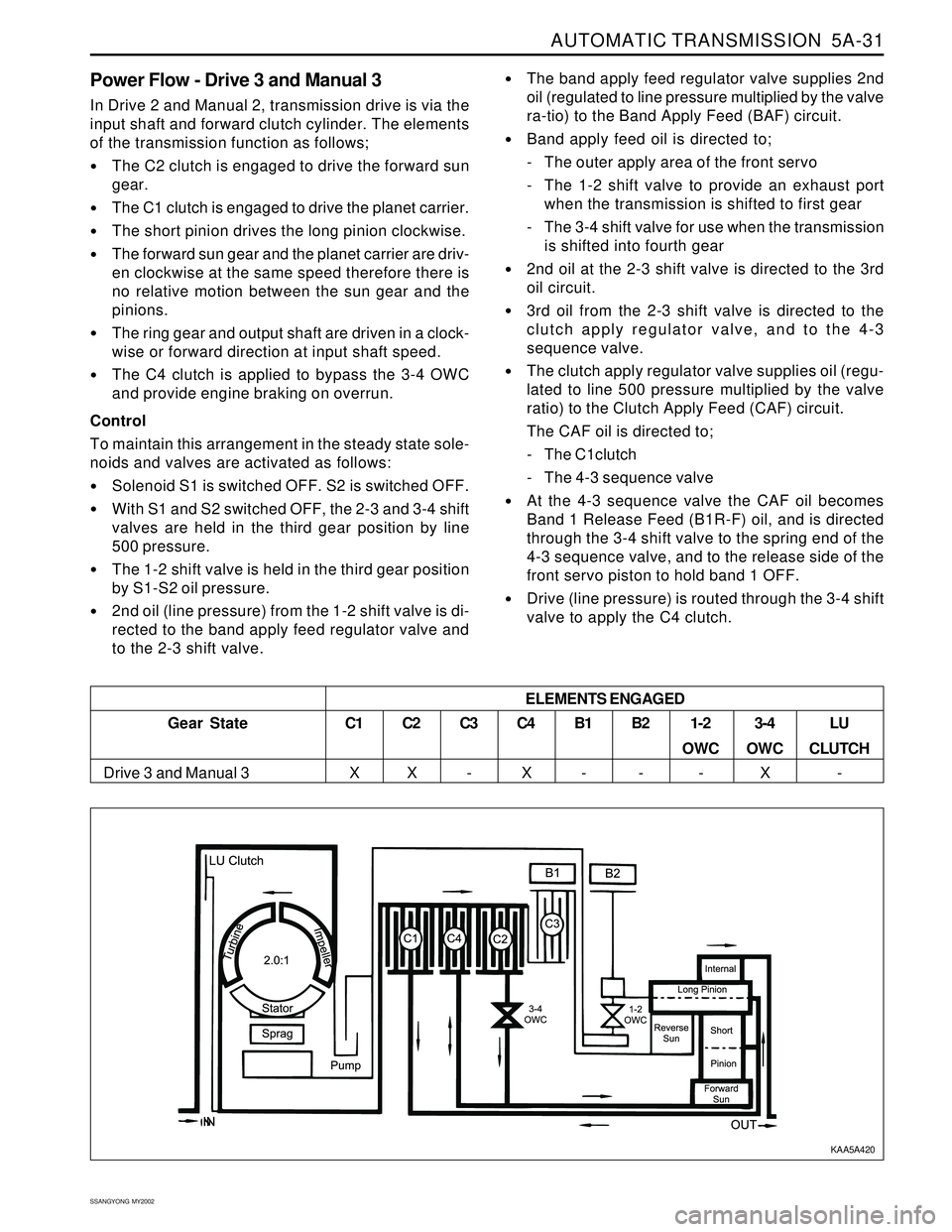
Power Flow - Drive 3 and Manual 3
In Drive 2 and Manual 2, transmission drive is via the
input shaft and forward clutch cylinder. The elements
of the transmission function as follows;
The C2 clutch is engaged to drive the forward sun
gear.
The C1 clutch is engaged to drive the planet carrier.
The short pinion drives the long pinion clockwise.
The forward sun gear and the planet carrier are driv-
en clockwise at the same speed therefore there is
no relative motion between the sun gear and the
pinions.
The ring gear and output shaft are driven in a clock-
wise or forward direction at input shaft speed.
The C4 clutch is applied to bypass the 3-4 OWC
and provide engine braking on overrun.
Control
To maintain this arrangement in the steady state sole-
noids and valves are activated as follows:
Solenoid S1 is switched OFF. S2 is switched OFF.
With S1 and S2 switched OFF, the 2-3 and 3-4 shift
valves are held in the third gear position by line
500 pressure.
The 1-2 shift valve is held in the third gear position
by S1-S2 oil pressure.
2nd oil (line pressure) from the 1-2 shift valve is di-
rected to the band apply feed regulator valve and
to the 2-3 shift valve.
The band apply feed regulator valve supplies 2nd
oil (regulated to line pressure multiplied by the valve
ra-tio) to the Band Apply Feed (BAF) circuit.
Band apply feed oil is directed to;
- The outer apply area of the front servo
- The 1-2 shift valve to provide an exhaust port
when the transmission is shifted to first gear
- The 3-4 shift valve for use when the transmission
is shifted into fourth gear
2nd oil at the 2-3 shift valve is directed to the 3rd
oil circuit.
3rd oil from the 2-3 shift valve is directed to the
clutch apply regulator valve, and to the 4-3
sequence valve.
The clutch apply regulator valve supplies oil (regu-
lated to line 500 pressure multiplied by the valve
ratio) to the Clutch Apply Feed (CAF) circuit.
The CAF oil is directed to;
- The C1clutch
- The 4-3 sequence valve
At the 4-3 sequence valve the CAF oil becomes
Band 1 Release Feed (B1R-F) oil, and is directed
through the 3-4 shift valve to the spring end of the
4-3 sequence valve, and to the release side of the
front servo piston to hold band 1 OFF.
Drive (line pressure) is routed through the 3-4 shift
valve to apply the C4 clutch.
3-4
OWC
XLU
CLUTCH
- ELEMENTS ENGAGED
Gear State
Drive 3 and Manual 3C1
XC2
XC3
-C4
XB1
-B2
-1-2
OWC
-
KAA5A420
Page 1129 of 2053
AUTOMATIC TRANSMISSION 5A-35
SSANGYONG MY2002
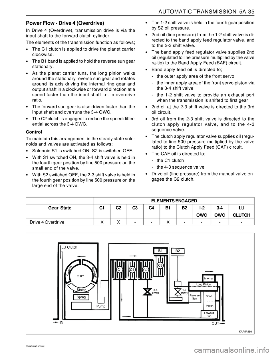
Power Flow - Drive 4 (Overdrive)
In Drive 4 (Overdrive), transmission drive is via the
input shaft to the forward clutch cylinder.
The elements of the transmission function as follows;
The C1 clutch is applied to drive the planet carrier
clockwise.
The B1 band is applied to hold the reverse sun gear
stationary.
As the planet carrier tuns, the long pinion walks
around the stationary reverse sun gear and rotates
around its axis driving the internal ring gear and
output shaft in a clockwise or forward direction at a
speed faster than the input shaft i.e. in overdrive
ratio.
The forward sun gear is also driven faster than the
input shaft and overruns the 3-4 OWC.
The C2 clutch is engaged to reduce the speed differ-
ential across the 3-4 OWC.
Control
To maintain this arrangement in the steady state sole-
noids and valves are activated as follows;
Solenoid S1 is switched ON. S2 is switched OFF.
With S1 switched ON, the 3-4 shift valve is held in
the fourth gear position by line 500 pressure on the
small end of the valve.
With S2 switched OFF, the 2-3 shift valve is held in
the fourth gear position by line 500 pressure on the
large end of the valve.
The 1-2 shift valve is held in the fourth gear position
by S2 oil pressure.
2nd oil (line pressure) from the 1-2 shift valve is di-
rected to the band apply feed regulator valve, and
to the 2-3 shift valve.
The band apply feed regulator valve supplies 2nd
oil (regulated to line pressure multiplied by the valve
ra-tio) to the Band Apply Feed (BAF) circuit.
Band apply feed oil is directed to;
- the outer apply area of the front servo
- the inner apply area of the front servo piston via
the 3-4 shift valve
- the 1-2 shift valve to provide an exhaust port
when the transmission is shifted to first gear
2nd oil at the 2-3 shift valve is directed to the 3rd
oil circuit.
3rd oil from the 2-3 shift valve is directed to the
clutch apply regulator valve, and to the 4-3
sequence valve.
The clutch apply regulator valve supplies oil (regu-
lated to line 500 pressure multiplied by the valve
ratio) to the Clutch Apply Feed (CAF) circuit.
The CAF oil is directed to;
- the C1 clutch
- the 4-3 sequence valve
Drive oil (line pressure) from the manual valve en-
gages the C2 clutch.
Gear State
Drive 4 Overdrive
C1
XC2
XC3
-C4
-B1
XB2
-1-2
OWC
-3-4
OWC
-LU
CLUTCH
- ELEMENTS ENGAGED
KAA5A460