1997 SSANGYONG KORANDO clock
[x] Cancel search: clockPage 1261 of 2053
5A-166 AUTOMATIC TRANSMISSION
SSANGYONG MY2002
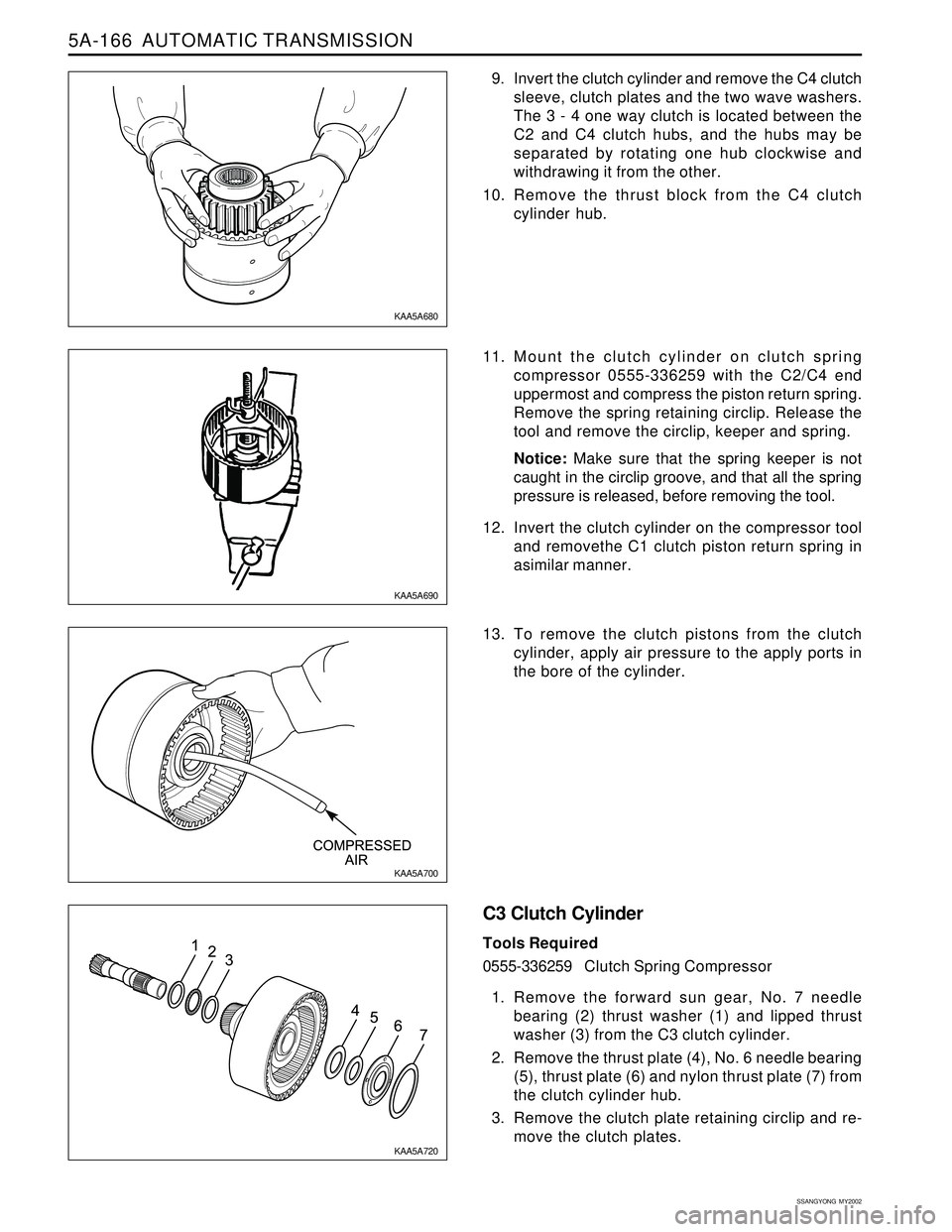
9. Invert the clutch cylinder and remove the C4 clutch
sleeve, clutch plates and the two wave washers.
The 3 - 4 one way clutch is located between the
C2 and C4 clutch hubs, and the hubs may be
separated by rotating one hub clockwise and
withdrawing it from the other.
10. Remove the thrust block from the C4 clutch
cylinder hub.
11. Mount the clutch cylinder on clutch spring
compressor 0555-336259 with the C2/C4 end
uppermost and compress the piston return spring.
Remove the spring retaining circlip. Release the
tool and remove the circlip, keeper and spring.
Notice: Make sure that the spring keeper is not
caught in the circlip groove, and that all the spring
pressure is released, before removing the tool.
12. Invert the clutch cylinder on the compressor tool
and removethe C1 clutch piston return spring in
asimilar manner.
13. To remove the clutch pistons from the clutch
cylinder, apply air pressure to the apply ports in
the bore of the cylinder.
C3 Clutch Cylinder
Tools Required
0555-336259Clutch Spring Compressor
1. Remove the forward sun gear, No. 7 needle
bearing (2) thrust washer (1) and lipped thrust
washer (3) from the C3 clutch cylinder.
2. Remove the thrust plate (4), No. 6 needle bearing
(5), thrust plate (6) and nylon thrust plate (7) from
the clutch cylinder hub.
3. Remove the clutch plate retaining circlip and re-
move the clutch plates.
KAA5A680
KAA5A690
KAA5A700
KAA5A720
Page 1262 of 2053
AUTOMATIC TRANSMISSION 5A-167
SSANGYONG MY2002
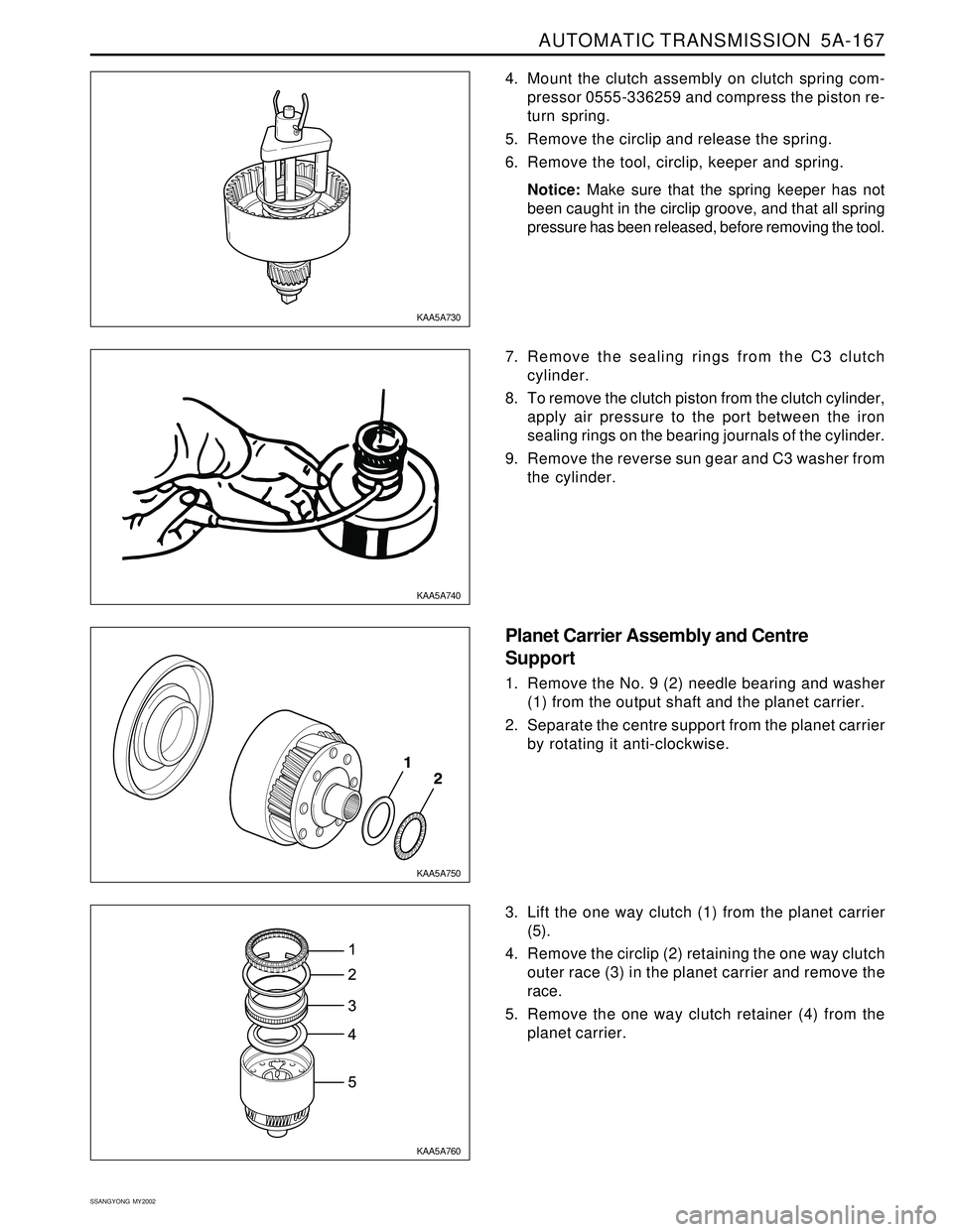
4. Mount the clutch assembly on clutch spring com-
pressor 0555-336259 and compress the piston re-
turn spring.
5. Remove the circlip and release the spring.
6. Remove the tool, circlip, keeper and spring.
Notice: Make sure that the spring keeper has not
been caught in the circlip groove, and that all spring
pressure has been released, before removing the tool.
7. Remove the sealing rings from the C3 clutch
cylinder.
8. To remove the clutch piston from the clutch cylinder,
apply air pressure to the port between the iron
sealing rings on the bearing journals of the cylinder.
9. Remove the reverse sun gear and C3 washer from
the cylinder.
Planet Carrier Assembly and Centre
Support
1. Remove the No. 9 (2) needle bearing and washer
(1) from the output shaft and the planet carrier.
2. Separate the centre support from the planet carrier
by rotating it anti-clockwise.
3. Lift the one way clutch (1) from the planet carrier
(5).
4. Remove the circlip (2) retaining the one way clutch
outer race (3) in the planet carrier and remove the
race.
5. Remove the one way clutch retainer (4) from the
planet carrier.
KAA5A750 KAA5A740 KAA5A730
KAA5A760
Page 1271 of 2053
5A-176 AUTOMATIC TRANSMISSION
SSANGYONG MY2002
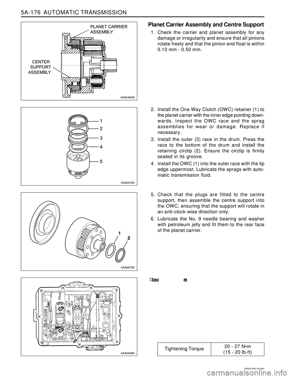
Planet Carrier Assembly and Centre Support
1. Check the carrier and planet assembly for any
damage or irregularity and ensure that all pinions
rotate freely and that the pinion end float is within
0.10 mm - 0.50 mm.
2. Install the One Way Clutch (OWC) retainer (1) to
the planet carrier with the inner edge pointing down-
wards. Inspect the OWC race and the sprag
assemblies for wear or damage. Replace if
necessary.
3. Install the outer (3) race in the drum. Press the
race to the bottom of the drum and install the
retaining circlip (2). Ensure the circlip is firmly
seated in its groove.
4. Install the OWC (1) into the outer race with the lip
edge uppermost. Lubricate the sprags with auto-
matic transmission fluid.
5. Check that the plugs are fitted to the centre
support, then assemble the centre support into
the OWC, ensuring that the support will rotate in
an anti-clock-wise direction only.
6. Lubricate the No. 9 needle bearing and washer
with petroleum jelly and fit them to the rear face
of the planet carrier.
7. In s t a l l th e
KAA5A0A0
KAA5A760
KAA5A750
KAA5A560
Tightening Torque20 - 27 Nm
(15 - 20 lb-ft)
Page 1277 of 2053
5A-182 AUTOMATIC TRANSMISSION
SSANGYONG MY2002
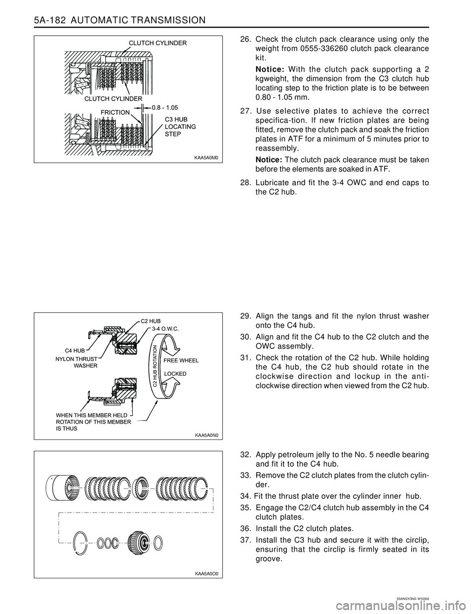
26. Check the clutch pack clearance using only the
weight from 0555-336260 clutch pack clearance
kit.
Notice: With the clutch pack supporting a 2
kgweight, the dimension from the C3 clutch hub
locating step to the friction plate is to be between
0.80 - 1.05 mm.
27. Use selective plates to achieve the correct
specifica-tion. If new friction plates are being
fitted, remove the clutch pack and soak the friction
plates in ATF for a minimum of 5 minutes prior to
reassembly.
Notice: The clutch pack clearance must be taken
before the elements are soaked in ATF.
28. Lubricate and fit the 3-4 OWC and end caps to
the C2 hub.
32. Apply petroleum jelly to the No. 5 needle bearing
and fit it to the C4 hub.
33. Remove the C2 clutch plates from the clutch cylin-
der.
34. Fit the thrust plate over the cylinder inner hub.
35. Engage the C2/C4 clutch hub assembly in the C4
clutch plates.
36. Install the C2 clutch plates.
37. Install the C3 hub and secure it with the circlip,
ensuring that the circlip is firmly seated in its
groove. 29. Align the tangs and fit the nylon thrust washer
onto the C4 hub.
30. Align and fit the C4 hub to the C2 clutch and the
OWC assembly.
31. Check the rotation of the C2 hub. While holding
the C4 hub, the C2 hub should rotate in the
clockwise direction and lockup in the anti-
clockwise direction when viewed from the C2 hub.
KAA5A0M0
KAA5A0N0
KAA5A0O0
Page 1441 of 2053
SSANGYONG MY2002
5D2-42 TRANSFER CASE (PART TIME - 4408)
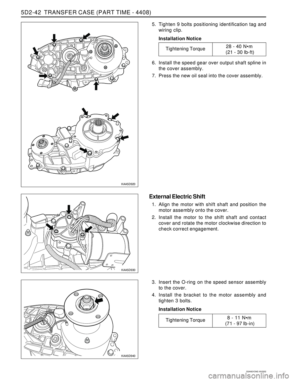
5. Tighten 9 bolts positioning identification tag and
wiring clip.
Installation Notice
6. Install the speed gear over output shaft spline in
the cover assembly.
7. Press the new oil seal into the cover assembly.
Tightening Torque28 - 40 Nm
(21 - 30 lb-ft)
KAA5D920
KAA5D930
KAA5D940
External Electric Shift
1. Align the motor with shift shaft and position the
motor assembly onto the cover.
2. Install the motor to the shift shaft and contact
cover and rotate the motor clockwise direction to
check correct engagement.
3. Insert the O-ring on the speed sensor assembly
to the cover.
4. Install the bracket to the motor assembly and
tighten 3 bolts.
Installation Notice
Tightening Torque8 - 11 Nm
(71 - 97 lb-in)
Page 1446 of 2053
SSANGYONG MY2002
6A-4 POWER STEERING SYSTEM
KAA6A020
DIAGNOSTIC INFORMATION AND PROCEDURES
POWER STEERING SYSTEM
PRESSURE TEST
Tools Required
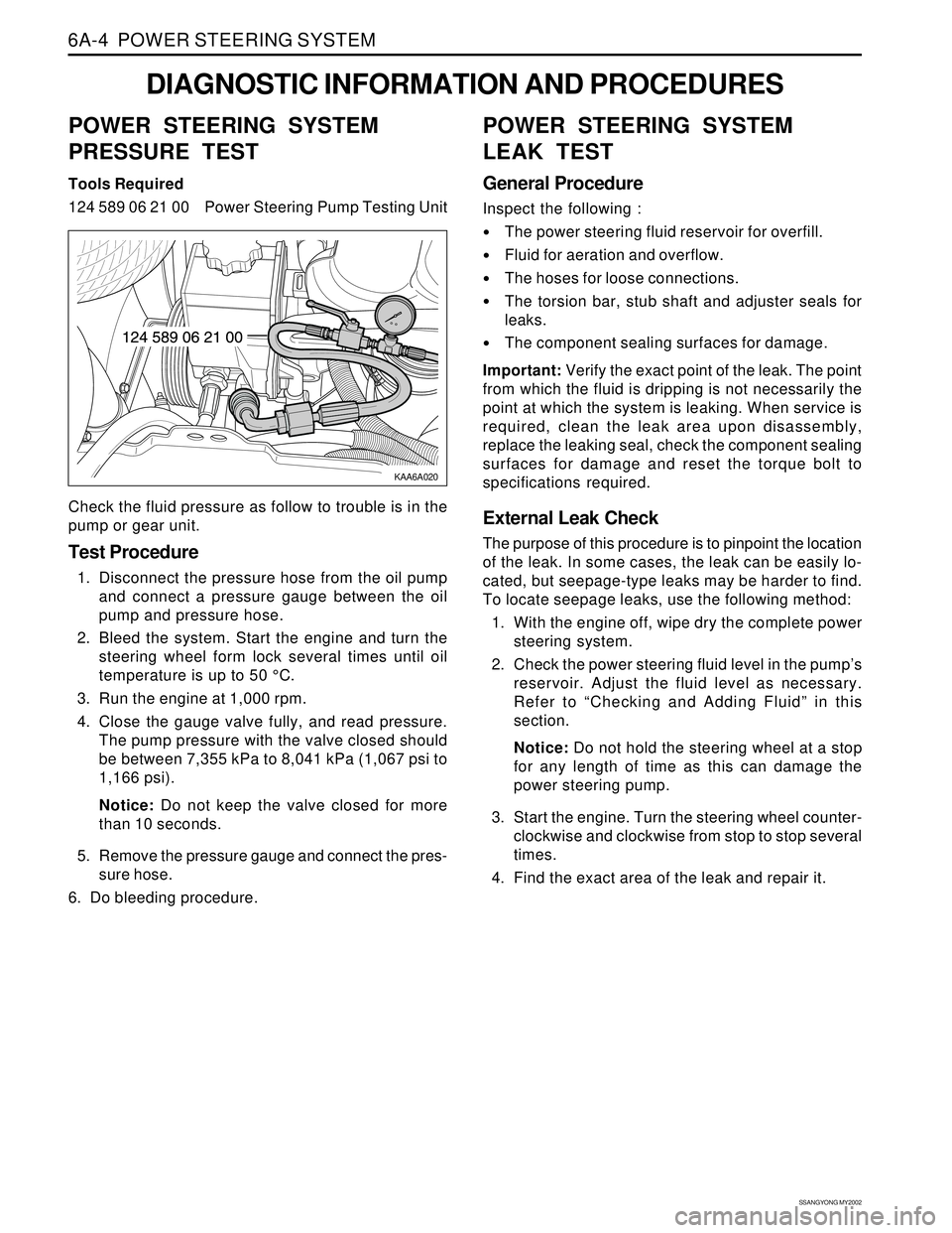
124 589 06 21 00 Power Steering Pump Testing Unit
Check the fluid pressure as follow to trouble is in the
pump or gear unit.
Test Procedure
1. Disconnect the pressure hose from the oil pump
and connect a pressure gauge between the oil
pump and pressure hose.
2. Bleed the system. Start the engine and turn the
steering wheel form lock several times until oil
temperature is up to 50 °C.
3. Run the engine at 1,000 rpm.
4. Close the gauge valve fully, and read pressure.
The pump pressure with the valve closed should
be between 7,355 kPa to 8,041 kPa (1,067 psi to
1,166 psi).
Notice: Do not keep the valve closed for more
than 10 seconds.
5. Remove the pressure gauge and connect the pres-
sure hose.
6. Do bleeding procedure.
POWER STEERING SYSTEM
LEAK TEST
General Procedure
Inspect the following :
The power steering fluid reservoir for overfill.
Fluid for aeration and overflow.
The hoses for loose connections.
The torsion bar, stub shaft and adjuster seals for
leaks.
The component sealing surfaces for damage.
Important: Verify the exact point of the leak. The point
from which the fluid is dripping is not necessarily the
point at which the system is leaking. When service is
required, clean the leak area upon disassembly,
replace the leaking seal, check the component sealing
surfaces for damage and reset the torque bolt to
specifications required.
External Leak Check
The purpose of this procedure is to pinpoint the location
of the leak. In some cases, the leak can be easily lo-
cated, but seepage-type leaks may be harder to find.
To locate seepage leaks, use the following method:
1. With the engine off, wipe dry the complete power
steering system.
2. Check the power steering fluid level in the pump’s
reservoir. Adjust the fluid level as necessary.
Refer to “Checking and Adding Fluid” in this
section.
Notice: Do not hold the steering wheel at a stop
for any length of time as this can damage the
power steering pump.
3. Start the engine. Turn the steering wheel counter-
clockwise and clockwise from stop to stop several
times.
4. Find the exact area of the leak and repair it.
Page 1455 of 2053
SSANGYONG MY2002
6A-4 POWER STEERING SYSTEM
KAA6A020
DIAGNOSTIC INFORMATION AND PROCEDURES
POWER STEERING SYSTEM
PRESSURE TEST
Tools Required
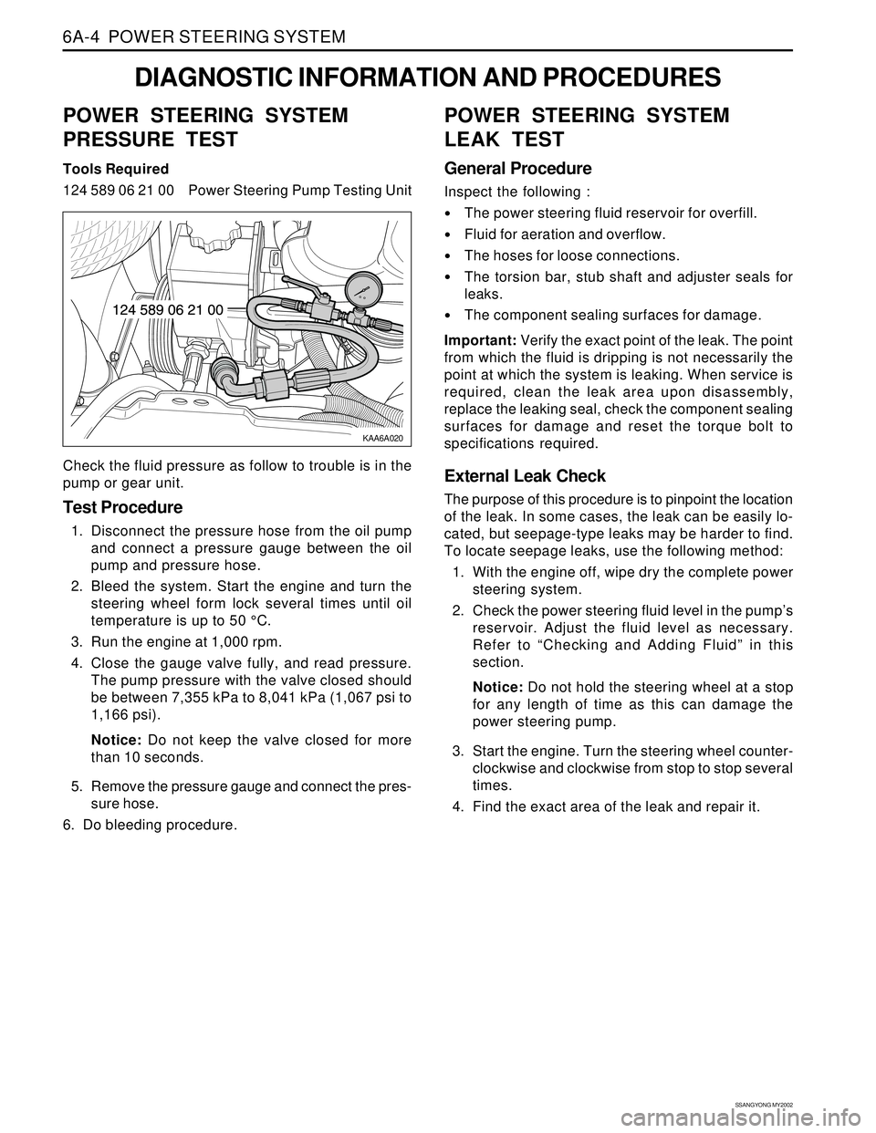
124 589 06 21 00 Power Steering Pump Testing Unit
Check the fluid pressure as follow to trouble is in the
pump or gear unit.
Test Procedure
1. Disconnect the pressure hose from the oil pump
and connect a pressure gauge between the oil
pump and pressure hose.
2. Bleed the system. Start the engine and turn the
steering wheel form lock several times until oil
temperature is up to 50 °C.
3. Run the engine at 1,000 rpm.
4. Close the gauge valve fully, and read pressure.
The pump pressure with the valve closed should
be between 7,355 kPa to 8,041 kPa (1,067 psi to
1,166 psi).
Notice: Do not keep the valve closed for more
than 10 seconds.
5. Remove the pressure gauge and connect the pres-
sure hose.
6. Do bleeding procedure.
POWER STEERING SYSTEM
LEAK TEST
General Procedure
Inspect the following :
The power steering fluid reservoir for overfill.
Fluid for aeration and overflow.
The hoses for loose connections.
The torsion bar, stub shaft and adjuster seals for
leaks.
The component sealing surfaces for damage.
Important: Verify the exact point of the leak. The point
from which the fluid is dripping is not necessarily the
point at which the system is leaking. When service is
required, clean the leak area upon disassembly,
replace the leaking seal, check the component sealing
surfaces for damage and reset the torque bolt to
specifications required.
External Leak Check
The purpose of this procedure is to pinpoint the location
of the leak. In some cases, the leak can be easily lo-
cated, but seepage-type leaks may be harder to find.
To locate seepage leaks, use the following method:
1. With the engine off, wipe dry the complete power
steering system.
2. Check the power steering fluid level in the pump’s
reservoir. Adjust the fluid level as necessary.
Refer to “Checking and Adding Fluid” in this
section.
Notice: Do not hold the steering wheel at a stop
for any length of time as this can damage the
power steering pump.
3. Start the engine. Turn the steering wheel counter-
clockwise and clockwise from stop to stop several
times.
4. Find the exact area of the leak and repair it.
Page 1465 of 2053
SSANGYONG MY2002
6B-4 POWER STEERING PUMP
KAA6B010
REPAIR INSTRUCTIONS
ON-VEHICLE SERVICE
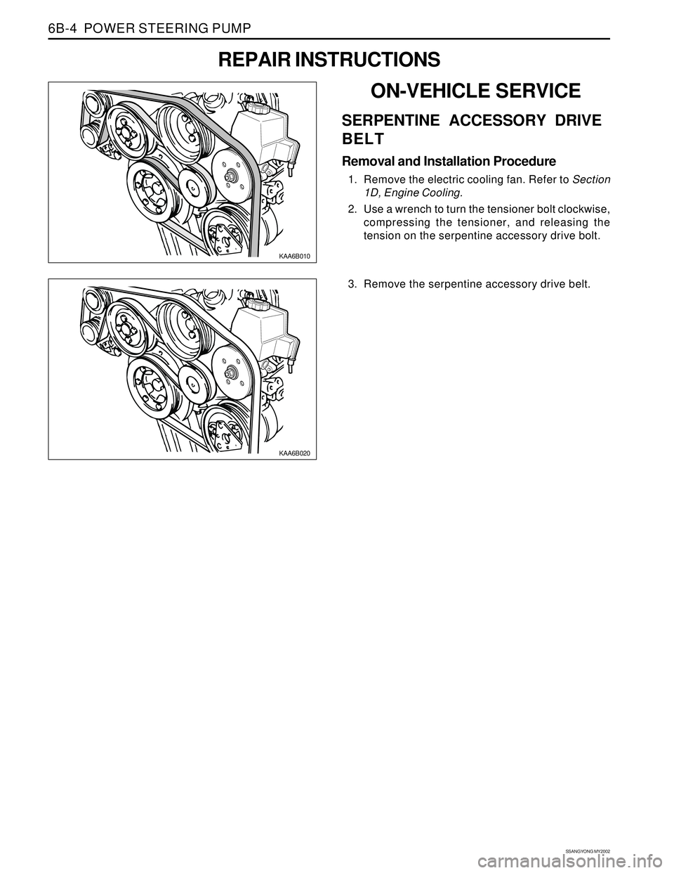
SERPENTINE ACCESSORY DRIVE
BELT
Removal and Installation Procedure
1. Remove the electric cooling fan. Refer to Section
1D, Engine Cooling.
2. Use a wrench to turn the tensioner bolt clockwise,
compressing the tensioner, and releasing the
tension on the serpentine accessory drive bolt.
KAA6B020
3. Remove the serpentine accessory drive belt.