1997 SSANGYONG KORANDO clock
[x] Cancel search: clockPage 1640 of 2053
SSANGYONG MY2002
8B-58 SUPPLEMENTAL RESTRAINTS SYSTEM
REPAIR INSTRUCTION
ON-VEHICLE SERVICE
SERVICE PRECAUTION
Caution: The sensing and diagnosis module (SDM)
can maintain sufficient voltage to deploy the airbags
and pretensioner for 0.15 seconds after the ignition
is OFF and the airbag fuse has been removed. If the
airbags or pretensioners are not disconnected, do
not begin service until one minute has passed after
disconnecting power to the SDM. If the airbag are
disconnected, service can begin immediately without
waiting for one-minute time period to expire. Failure
to temporarily disable the SRS during service can
result in unexpected deployment, personal injury,
and otherwise unneeded SRS repairs.
DISABLING THE SUPPLEMENTAL
RESTRAINT SYSTEM (SRS)
1. Turn the steering wheel to the straight-ahead
position.
2. Turn the ignition switch to LOCK and remove the key.
3. Remove the airbag fuse F31 in the I/P fuse block
and wait more than one minute for SRS capacitor to
discharge.
ENABLING THE SUPPLEMENTAL
RESTRAINT SYSTEM (SRS)
Enabling the supplemental restraint system (SRS) is
reverse order of “Disabling the Supplemental Restraint
System (SRS)”.
Caution: Staying well away from the inflator
modules, turn the ignition key switch to ON, and
verify that the airbag indicator illuminates for 4.5
seconds and turns OFF. If it does not operate as
described, perform the “SRS Diagnostic System
Check” referring in this section.
HANDLING, INSTALLATION AND
DIAGNOSIS
Airbag modules should not be subjected to
temperature above 65°C (149°F)
An airbag module or sensing and diagnostic module
(SDM) should not be used if it has been dropped
from height of 0.9 meters (3 feet) or greater.
It is very important for the SDM to be installed flat
on the mounting surface, parallel to the vehicle’s
longitudinal axis.
To avoid setting diagnostic trouble codes (DTCs),
do not apply power to the SRS unless all components
are connected or a diagnostic chart request it.
The SRS Diagnostic System Check must be the
starting point of any SRS diagnostics. The SRS
Diagnostic System Check will verify proper airbag
indicator operation and will lead you to correct chart
to diagnose any SRS malfunctions. Bypassing
these procedures may result in extended diagnostic
time and incorrect parts replacements.
REPAIRS AND INSPECTIONS
REQUIRED AFTER AN ACCIDENT
Caution: any repairs to the vehicle’s structure must
return it to the original production configuration.
Deployment requires replacement of SDM, the
inflator modules, and a dimensional inspection of
the steering column.
If any SRS components are damaged, they must
be replaced. If SRS components mounting points
are damaged, they must be repaired or replaced.
Never use SRS parts from another vehicle. This does
not include remanufactured parts purchased from
an authorized source.
Do not attempt to service the SDM, the clock spring,
or other airbag modules, these items must be
replaced if they are defective.
Verify the part number of replacement airbag
modules. Some inflator modules look identical but
contain different internal components.
ACCIDENT WITH DEPLOYMENT -
COMPONENTS REPLACEMENT
All SRS components must be replaced after frontal crash
involving airbag deployment. After deployment, a
powdery residue may be on the surface of the airbag.
The powder consists primarily of cornstarch (used to
lubricate the bag as it inflates) and by-products of the
chemical reaction. Sodium hydroxide dust (similar to
lye soap) is produced as a by-product of the deployment
reaction. The sodium hydroxide then quickly reacts with
atmospheric moisture and is converted to sodium
carbonate and sodium bicarbonate (also known as
baking soda). Therefore, it is unlikely that sodium
hydroxide will be present after deployment. Replace
the following SRS components.
Caution: Wear gloves and safety glasses during the
disposal procedure. Refer to “Deployed Airbag
Module Disposal Procedure” in this section.
The SDM.
Airbag modules and pretensioners
SRS wiring
Clock spring
Page 1643 of 2053
SUPPLEMENTAL RESTRAINTS SYSTEM 8B-61
SSANGYONG MY2002
KAA8B050
CLOCK SPRING
Removal and installation Procedure
Caution: The SDM can maintain sufficient voltage
to deploy the airbags for 0.15 seconds after the
Ignition is OFF and the airbag fuse has been
removed. If the airbags are not disconnected, service
cannot begin until one minute has passed after
disconnecting power to the SDM. If the airbags are
disconnected, service can begin immediately
without waiting for one-minute time period to
expire. Failure to temporarily disable the SRS
during service result in unexpected deployment,
personal injury, and otherwise unneeded SRS repair.
1. Disconnect the negative battery cable.
2. Remove the driver airbag module. Refer to “Driver
Airbag Module” in this section.
3. Remove the steering wheel. Refer to Section 6E,
Steering Wheel and Column.
4. Remove the steering column cover. Refer to
Section 6E, Steering Wheel and Column.
5. Carefully full the instrument panel lower cover.
6. Remove driver side knee bolster.
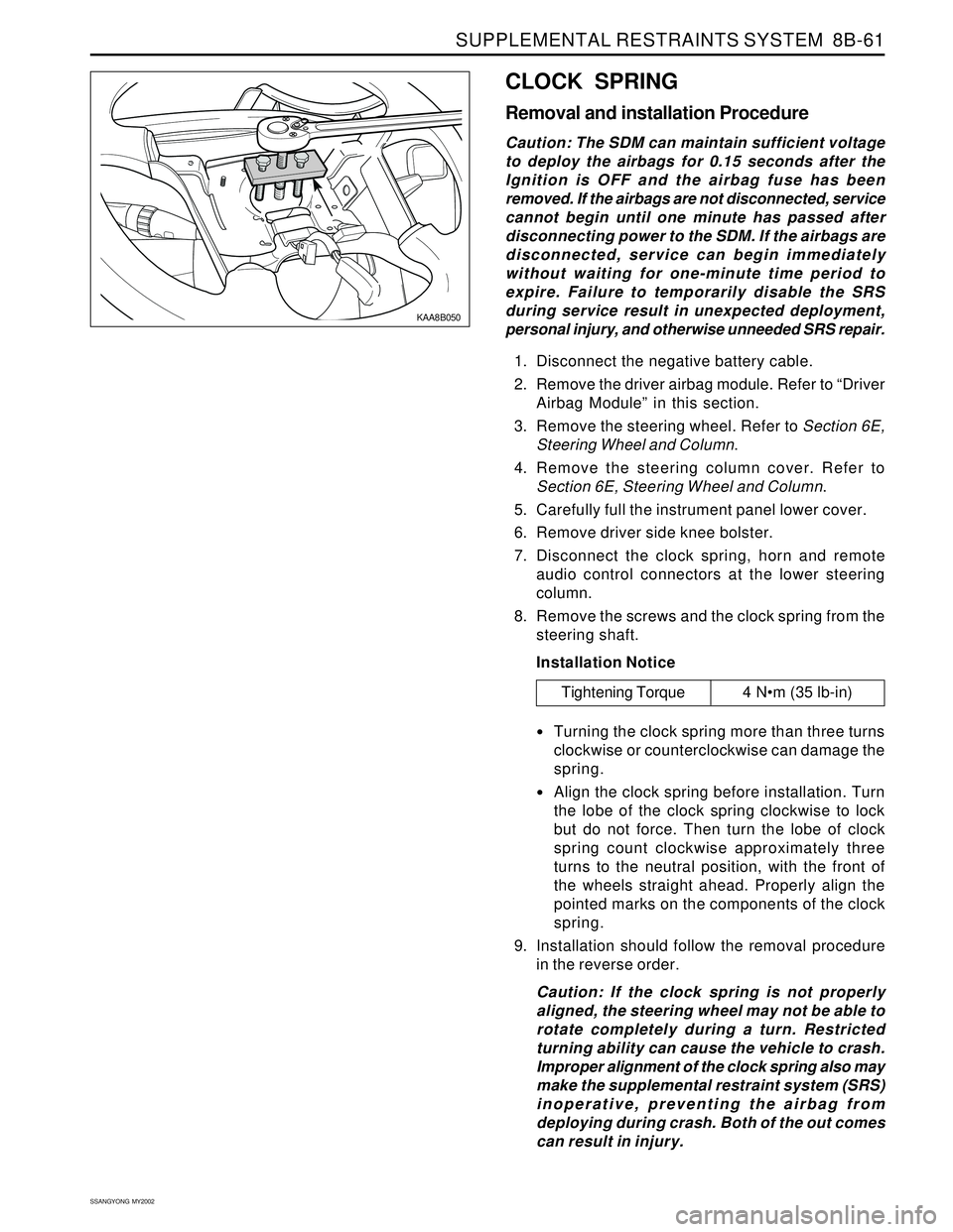
7. Disconnect the clock spring, horn and remote
audio control connectors at the lower steering
column.
8. Remove the screws and the clock spring from the
steering shaft.
Installation Notice
Turning the clock spring more than three turns
clockwise or counterclockwise can damage the
spring.
Align the clock spring before installation. Turn
the lobe of the clock spring clockwise to lock
but do not force. Then turn the lobe of clock
spring count clockwise approximately three
turns to the neutral position, with the front of
the wheels straight ahead. Properly align the
pointed marks on the components of the clock
spring.
9. Installation should follow the removal procedure
in the reverse order.
Caution: If the clock spring is not properly
aligned, the steering wheel may not be able to
rotate completely during a turn. Restricted
turning ability can cause the vehicle to crash.
Improper alignment of the clock spring also may
make the supplemental restraint system (SRS)
inoperative, preventing the airbag from
deploying during crash. Both of the out comes
can result in injury.
Tightening Torque 4 Nm (35 lb-in)
Page 1645 of 2053
SUPPLEMENTAL RESTRAINTS SYSTEM 8B-63
SSANGYONG MY2002
KAA8B170
AIRBAG MODULE DEPLOYMENT
(IN VEHICLE)
Deploy airbags before disposing of them. If a vehicle to be
scraped, the airbag may be deployed inside the vehicle.
Caution: To avoid injury while deploying an airbag
or a pretensioner in the vehicle, observe the
following precaution:
Before deploying the airbags, remove all loose
objects from the airbag’s expansion area.
Deploy the airbags with the vehicle doors closed
and the side windows open.
Deploy the airbags only in an evacuated area.
Service personnel who must be present during
the deployment should be at least 10 meters (33
feet) in front of the vehicle.
Do not connect the voltage source until after
having completed all other preparations for the
deployment of the airbags.
Allow a deployed airbag module or pretensioner
to cool for at least 30 minutes before handling.
Wear gloves and eye protection during the
disposal procedure.
If the deployment fails, disconnect the voltage
source and wait 5 minutes before approaching
the vehicle.
Deployment Procedure
Caution: The SDM can maintain sufficient voltage
to deploy the airbags for 0.15 seconds after the
Ignition is OFF and the airbag fuse has been
removed. If the airbags are not disconnected, service
cannot begin until one minute has passed after
disconnecting power to the SDM. If the airbags are
disconnected, service can begin immediately
without waiting for one-minute time period to
expire. Failure to temporarily disable the SRS
during service result in unexpected deployment,
personal injury, and otherwise unneeded SRS repair.
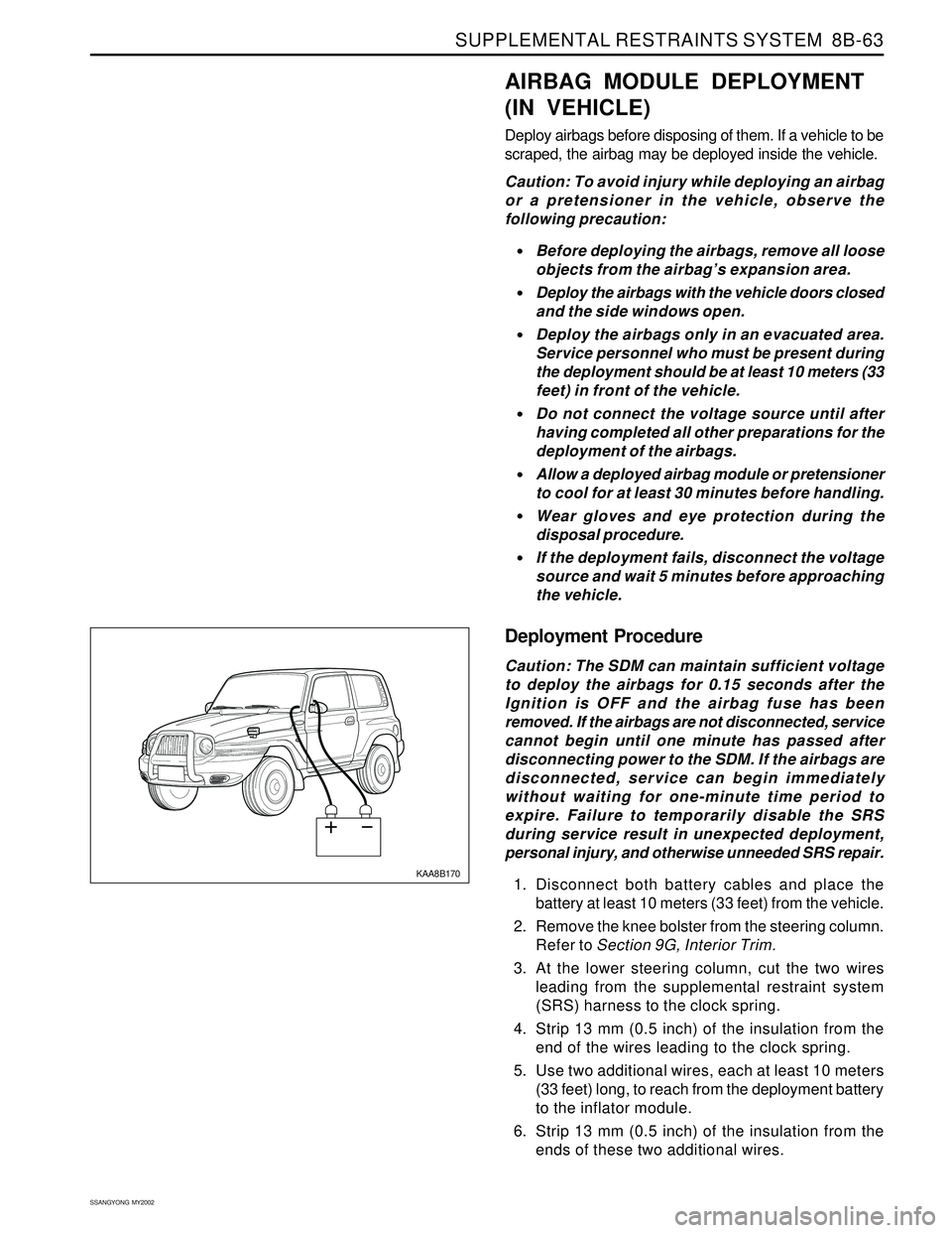
1. Disconnect both battery cables and place the
battery at least 10 meters (33 feet) from the vehicle.
2. Remove the knee bolster from the steering column.
Refer to Section 9G, Interior Trim.
3. At the lower steering column, cut the two wires
leading from the supplemental restraint system
(SRS) harness to the clock spring.
4. Strip 13 mm (0.5 inch) of the insulation from the
end of the wires leading to the clock spring.
5. Use two additional wires, each at least 10 meters
(33 feet) long, to reach from the deployment battery
to the inflator module.
6. Strip 13 mm (0.5 inch) of the insulation from the
ends of these two additional wires.
Page 1646 of 2053

SSANGYONG MY2002
8B-64 SUPPLEMENTAL RESTRAINTS SYSTEM
7. Twist the two wires together at one end.
8. Place the twisted ends of the two wires near the
deployment battery. Do not connect the wires to
the battery at this time.
9. Using the free ends of the 10 meters (33 feet) wires
leading to the clock spring, make two splices, one
at each wires from the airbag modules.
10. Wrap the wires with insulation tape.
11. Now that the free ends of the 10 meters (33 feet)
wires are spliced to the airbag module wires, and
the ends that are twisted together are near the
deployment battery, clear the area.
12. Untwist the wires that near the deployment
battery.
13. Touch one wire to the positive battery terminal and
touch the other wire to the negative battery
terminal. The airbag will deploy.
14. Repeat the procedure for the passenger airbag
and pretensioners.
15. Using proper precautions, dispose of the deployed
airbag/pretensioner. Refer to “Deployed Airbag
Module Disposal Procedure” in this section.
Page 1649 of 2053
SUPPLEMENTAL RESTRAINTS SYSTEM 8B-67
SSANGYONG MY2002
SPECIFICATIONS
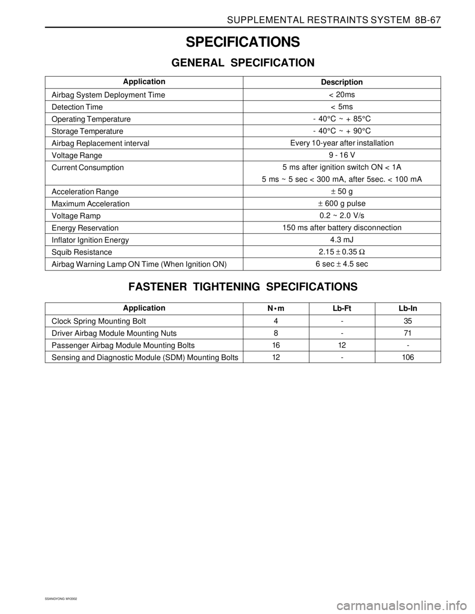
GENERAL SPECIFICATION
Nm
4
8
16
12Lb-Ft
-
-
12
- Clock Spring Mounting Bolt
Driver Airbag Module Mounting Nuts
Passenger Airbag Module Mounting Bolts
Sensing and Diagnostic Module (SDM) Mounting BoltsLb-In
35
71
-
106Application
Description
< 20ms
< 5ms
- 40°C ~ + 85°C
- 40°C ~ + 90°C
Every 10-year after installation
9 - 16 V
5 ms after ignition switch ON < 1A
5 ms ~ 5 sec < 300 mA, after 5sec. < 100 mA
± 50 g
± 600 g pulse
0.2 ~ 2.0 V/s
150 ms after battery disconnection
4.3 mJ
2.15 ± 0.35 Ω
6 sec ± 4.5 sec Airbag System Deployment Time
Detection Time
Operating Temperature
Storage Temperature
Airbag Replacement interval
Voltage Range
Current Consumption
Acceleration Range
Maximum Acceleration
Voltage Ramp
Energy Reservation
Inflator Ignition Energy
Squib Resistance
Airbag Warning Lamp ON Time (When Ignition ON)Application
FASTENER TIGHTENING SPECIFICATIONS
Page 1658 of 2053
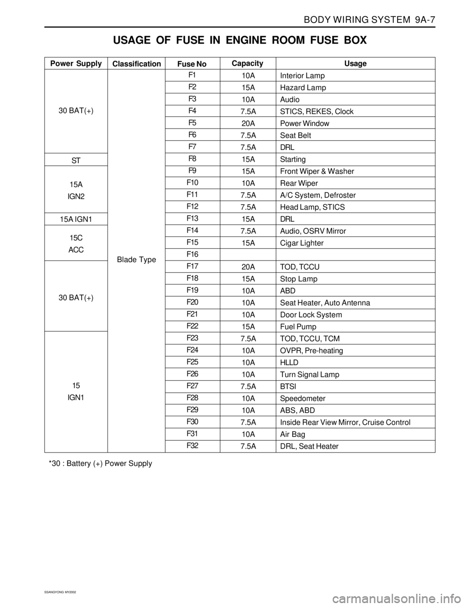
BODY WIRING SYSTEM 9A-7
SSANGYONG MY2002
USAGE OF FUSE IN ENGINE ROOM FUSE BOX
Interior Lamp
Hazard Lamp
Audio
STICS, REKES, Clock
Power Window
Seat Belt
DRL
Starting
Front Wiper & Washer
Rear Wiper
A/C System, Defroster
Head Lamp, STICS
DRL
Audio, OSRV Mirror
Cigar Lighter
TOD, TCCU
Stop Lamp
ABD
Seat Heater, Auto Antenna
Door Lock System
Fuel Pump
TOD, TCCU, TCM
OVPR, Pre-heating
HLLD
Turn Signal Lamp
BTSI
Speedometer
ABS, ABD
Inside Rear View Mirror, Cruise Control
Air Bag
DRL, Seat Heater Power SupplyUsage
Classification
Fuse NoCapacity
30 BAT(+)
ST
15A
IGN2
15A IGN1
15C
ACC
30 BAT(+)
15
IGN1
Blade TypeF1
F2
F3
F4
F5
F6
F7
F8
F9
F10
F11
F12
F13
F14
F15
F16
F17
F18
F19
F20
F21
F22
F23
F24
F25
F26
F27
F28
F29
F30
F31
F3210A
15A
10A
7.5A
20A
7.5A
7.5A
15A
15A
10A
7.5A
7.5A
15A
7.5A
15A
20A
15A
10A
10A
10A
15A
7.5A
10A
10A
10A
7.5A
10A
10A
7.5A
10A
7.5A
*30 : Battery (+) Power Supply
Page 1718 of 2053

SECTION 9E
INSTRUMENTATION, DRIVER INFORMATION
CAUTION: Disconnect the negative battery cable before removing or installing any electrical unit or when a
tool or equipment could easily come in contact with exposed electrical terminals. Disconnecting this cable
will help prevent personal injury and damage to the vehicle. The ignition must also be in LOCK unless
otherwise noted.
TABLE OF CONTENTS
Description and Operation.................................. 9E-2
Cigar Lighter....................................................... 9E-2
Ashtray.............................................................. 9E-2
Instrument Panel Vents....................................... 9E-2
Glove Box.......................................................... 9E-2
Digital Clock....................................................... 9E-2
Instrument Cluster.............................................. 9E-2
Speedometer and Tachometer............................ 9E-2
Trip Odometer.................................................... 9E-2
Fuel Gauge......................................................... 9E-2
Temperature Gauge............................................ 9E-2
Instrument Cluster Indicator Lamps..................... 9E-2
Chime Module.................................................... 9E-2
Components Locator ........................................... 9E-3
Instrumentation/Driver Information....................... 9E-3
Diagnostic Information and Procedure.............. 9E-5
Cigar Lighter....................................................... 9E-5
Disital Clock....................................................... 9E-5
Speedo Meter..................................................... 9E-6
Fuel Gauge......................................................... 9E-7
Temperature Gauge............................................ 9E-8
Instrument Cluster Indicator Lamps..................... 9E-9
Repair Instructions............................................. 9E-10
On-Vehice Service Unit Repair............................. 9E-10
Center Tray....................................................... 9E-10
Center Facia..................................................... 9E-10
Ashtray............................................................ 9E-10
Cigar Lighter..................................................... 9E-11Cup Holder....................................................... 9E-11
Instrument Panel Vent....................................... 9E-11
Glove Box........................................................ 9E-12
Chime Module.................................................. 9E-12
Hood Latch Release Handle.............................. 9E-12
Instrument Lower Cover.................................... 9E-13
Instrument Cluster Trim Panel........................... 9E-13
Instrument Cluster............................................ 9E-13
Speedometer/Odometer/Trip Odometer/
Tachometer................................................... 9E-14
Fuel Gauge....................................................... 9E-14
Temperature Gauge .......................................... 9E-15
Digital Clock..................................................... 9E-15
Instrument Cluster Indicator Lamps................... 9E-15
Instrument Panel............................................... 9E-16
Specifications.................................................... 9E-18
Bulb Usage Chart............................................. 9E-18
Schematic and Routing Diagram..................... 9E-19
Instrument Panel Illumination............................ 9E-19
Cluster (VSS, Meter & Gauge): Diesel.................9E-20
Cluster (VSS, Meter & Gauge): Gasoline............ 9E-21
Warning Lamp, TCS Indicator........................... 9E-22
Indicator........................................................... 9E-23
Warning Lamp.................................................. 9E-24
Digital Clock, Warning Cluster Illumination......... 9E-25
Selector Lever Position Lamp............................ 9E-26
Page 1719 of 2053

SSANGYONG MY2002
9E-2 INSTRUMENTATION, DRIVER INFORMATION
DESCRIPTION AND OPERATION
CIGAR LIGHTER
The cigar lighter is located in the front portion of the
floor console. To use the lighter, push it in completely.
When the lighter is hot, it will release itsef from contact
with the heating element. The lighter and the heating
element can be damaged if the lighter does not fully
release itsef from the heating element.
ASHTRAY
The ashtray is located in the console. To access the
ashtray, pullit out of the ashtray housing. The ashtray
lamp will go on when the parking lamps or headlamps
are turned on.
INSTRUMENT PANEL VENTS
The center and the side vents in the instrument panel
can be adjusted up and down and from side to side.
The side vents can also be aimed toward the side
windows to defog them.
GLOVE BOX
The glove box can be opened by pulling upon the latch
handle.
DIGITAL CLOCK
The digital clock is located in the instrument cluster.
INSTRUMENT CLUSTER
The instrument cluster is located above the steering
column and in the instrument cluster trim panel. The
instrument cluster contains the instruments that
provide the driver with vehicle performance information.
The instrument cluster contains a speedometer, a
tachometer, an odometer, a trip odometer, a
temperature gauge, a fuel gauge, and several indicator
lamps. For replacement of the indicator lamp bulbs
contained in the instrument cluster, refer to “Instrument
Cluster Indicator Lamps Specifications” in the section.
SPEEDOMETER AND
TACHOMETER
The speedometer measures the speed of the vehicle
in km/h (with mph) or mph (with km/h). It consists of
an instrument cluster gauge connected to the vehicle
speed sensor on the transaxle output shaft. The
tachometer measures the engine’s speed in terms of
thousands of revolutions per minute. It consists of an
instrument cluster gauge connected to a sending unit
in the engine con-trol module. Do not operate the
engine in the red zone. Engine damage may occur.
TRIP ODOMETER
The trip odometer measures the distance the vehicle
has traveled since it was last reset. It consists of an
instrument cluster gauge connected to the sending unit
on the tasnsaxle output shaft. The trip oddometer can
be record the distance traveled from any starting point.
FUEL GAUGE
The fuel gauge consists of an instrument cluster gauge
connected to a sending unit in the fuel tank. The fuel
gauge indicates the quantity of fuel in the tank only
when the ignition is turned to ON or ACC. When the
ignition is turned to LOCK or START, the pointer may
come to rest at any position.
TEMPERATURE GAUGE
The temperature gauge consists of an instrument
cluster gauge connected to a temperature sensor that
is in con-tact with the circulating engine coolant. The
temperature gauge indicates the temperature of the
coolant. Prolonged driving or idling in very hot weather
may cause the pointer to move beyond the center of
the gauge. The engine is overheating if the pointer
moves into the red zone at the upper limit of the gauge.
INSTRUMENT CLUSTER
INDICATOR LAMPS
The instrument cluster contains indicator lamps that
indicatethe functioning of certain systems or the
existenceof potential problems with the operation of
the vehicle. The indicator lamps are replaceable. For
replacement of the indicator lamps contained in the
instrument cluster, refer to “instrument cluster indicator
lamps specifications” in this section.
CHIME MODULE
The chime module will sound to bring attention to one
or more of the following conditions:
The lights are on and the ignition not in ACC, ON,
or START.
The ignition key is in the ignition switch when the
driver’s side door is open.
The seat belt is unbuckled when the ignition is in
ACC, ON, or START.
Voltage is supplied at all times through the fuse block
to power the chime module.