1997 SSANGYONG KORANDO clock
[x] Cancel search: clockPage 1722 of 2053
INSTRUMENTATION, DRIVER INFORMATION 9E-5
SSANGYONG MY2002
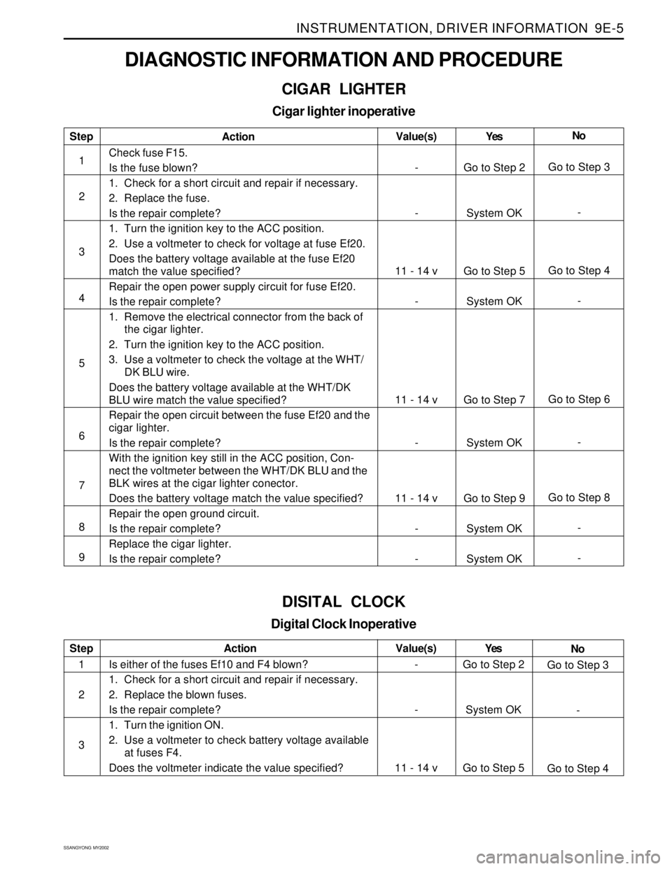
DIAGNOSTIC INFORMATION AND PROCEDURE
CIGAR LIGHTER
Cigar lighter inoperative
Step
1
2
3
4
5
6
7
8
9Action
Check fuse F15.
Is the fuse blown?
1. Check for a short circuit and repair if necessary.
2. Replace the fuse.
Is the repair complete?
1. Turn the ignition key to the ACC position.
2. Use a voltmeter to check for voltage at fuse Ef20.
Does the battery voltage available at the fuse Ef20
match the value specified?
Repair the open power supply circuit for fuse Ef20.
Is the repair complete?
1. Remove the electrical connector from the back of
the cigar lighter.
2. Turn the ignition key to the ACC position.
3. Use a voltmeter to check the voltage at the WHT/
DK BLU wire.
Does the battery voltage available at the WHT/DK
BLU wire match the value specified?
Repair the open circuit between the fuse Ef20 and the
cigar lighter.
Is the repair complete?
With the ignition key still in the ACC position, Con-
nect the voltmeter between the WHT/DK BLU and the
BLK wires at the cigar lighter conector.
Does the battery voltage match the value specified?
Repair the open ground circuit.
Is the repair complete?
Replace the cigar lighter.
Is the repair complete?Yes
Go to Step 2
System OK
Go to Step 5
System OK
Go to Step 7
System OK
Go to Step 9
System OK
System OKNo
Go to Step 3
-
Go to Step 4
-
Go to Step 6
-
Go to Step 8
-
- Value(s)
-
-
11 - 14 v
-
11 - 14 v
-
11 - 14 v
-
-
DISITAL CLOCK
Digital Clock Inoperative
Step
1
2
3Action
Is either of the fuses Ef10 and F4 blown?
1. Check for a short circuit and repair if necessary.
2. Replace the blown fuses.
Is the repair complete?
1. Turn the ignition ON.
2. Use a voltmeter to check battery voltage available
at fuses F4.
Does the voltmeter indicate the value specified?Yes
Go to Step 2
System OK
Go to Step 5No
Go to Step 3
-
Go to Step 4 Value(s)
-
-
11 - 14 v
Page 1723 of 2053
SSANGYONG MY2002
9E-6 INSTRUMENTATION, DRIVER INFORMATION
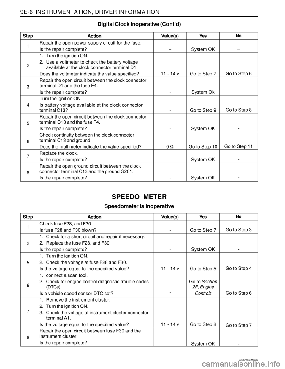
Digital Clock Inoperative (Cont’d)
Step
1
2
3
4
5
6
7
8Action
Repair the open power supply circuit for the fuse.
Is the repair complete?
1. Turn the ignition ON.
2. Use a voltmeter to check the battery voltage
available at the clock connector terminal D1.
Does the voltmeter indicate the value specified?
Repair the open circuit between the clock connector
terminal D1 and the fuse F4.
Is the repair complete?
Turn the ignition ON.
Is battery voltage available at the clock connector
terminal C13?
Repair the open circuit between the clock connector
terminal C13 and the fuse F4.
Is the repair complete?
Check continuity between the clock connector
terminal C13 and ground.
Does the multimeter indicate the value specified?
Replace the clock.
Is the repair complete?
Repair the open ground circuit between the clock
connector terminal C13 and the ground G201.
Is the repair complete?Yes
System OK
Go to Step 7
System Ok
Go to Step 9
System OK
Go to Step 10
System OK
System OKNo
−
Go to Step 6
-
Go to Step 8
-
Go to Step 11
-
- Value(s)
−
11 - 14 v
-
-
-
0 Ω
-
-
SPEEDO METER
Speedometer Is Inoperative
Step
1
2
5
6
7
8Action
Check fuse F28, and F30.
Is fuse F28 and F30 blown?
1. Check for a short circuit and repair if necessary.
2. Replace the fuse F28, and F30.
Is the repair complete?
1. Turn the ignition ON.
2. Check the voltage at fuse F28 and F30.
Is the voltage equal to the specified value?
1. connect a scan tool.
2. Check for engine control diagnostic trouble codes
(DTCs).
Is a vehicle speed sensor DTC set?
1. Remove the instrument cluster.
2. Turn the ignition ON.
3. Check the voltage at instrument cluster connector
terminal A1.
Is the voltage equal to the specified value?
Repair the open circuit between fuse F30 and the
instrument cluster.
Is the repair complete?Yes
Go to Step 7
System OK
Go to Step 5
Go to Section
2F, Engine
Controls
Go to Step 8
System OKNo
Go to Step 3
-
Go to Step 4
Go to Step 6
Go to Step 7
- Value(s)
-
-
11 - 14 v
-
11 - 14 v
-
Page 1731 of 2053
SSANGYONG MY2002
9E-14 INSTRUMENTATION, DRIVER INFORMATION
KAA9E170
KAA9E180
KAA9E190
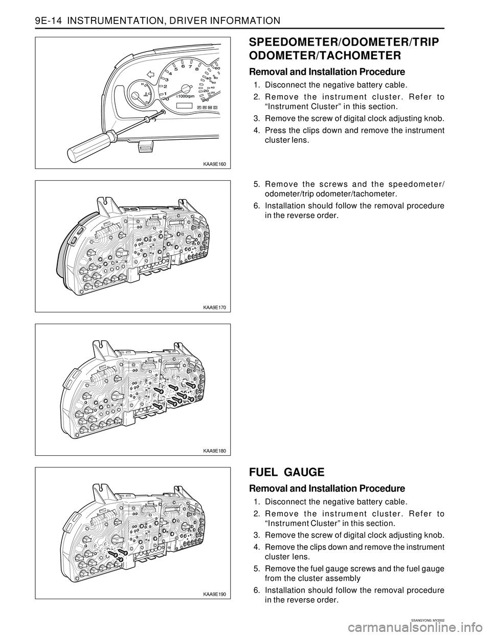
5. Remove the screws and the speedometer/
odometer/trip odometer/tachometer.
6. Installation should follow the removal procedure
in the reverse order.
FUEL GAUGE
Removal and Installation Procedure
1. Disconnect the negative battery cable.
2. Remove the instrument cluster. Refer to
“Instrument Cluster” in this section.
3. Remove the screw of digital clock adjusting knob.
4. Remove the clips down and remove the instrument
cluster lens.
5. Remove the fuel gauge screws and the fuel gauge
from the cluster assembly
6. Installation should follow the removal procedure
in the reverse order.
KAA9E160
SPEEDOMETER/ODOMETER/TRIP
ODOMETER/TACHOMETER
Removal and Installation Procedure
1. Disconnect the negative battery cable.
2. Remove the instrument cluster. Refer to
“Instrument Cluster” in this section.
3. Remove the screw of digital clock adjusting knob.
4. Press the clips down and remove the instrument
cluster lens.
Page 1732 of 2053
INSTRUMENTATION, DRIVER INFORMATION 9E-15
SSANGYONG MY2002
KAA9E210
KAA9E220
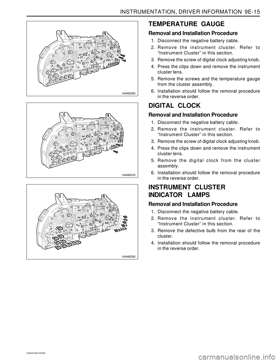
DIGITAL CLOCK
Removal and Installation Procedure
1. Disconnect the negative battery cable.
2. Remove the instrument cluster. Refer to
“Instrument Cluster” in this section.
3. Remove the screw of digital clock adjusting knob.
4. Press the clips down and remove the instrument
cluster lens.
5. Remove the digital clock from the cluster
assembly.
6. Installation should follow the removal procedure
in the reverse order.
KAA9E200
TEMPERATURE GAUGE
Removal and Installation Procedure
1. Disconnect the negative battery cable.
2. Remove the instrument cluster. Refer to
“Instrument Cluster” in this section.
3. Remove the screw of digital clock adjusting knob.
4. Press the clips down and remove the instrument
cluster lens.
5. Remove the screws and the temperature gauge
from the cluster assembly.
6. Installation should follow the removal procedure
in the reverse order.
INSTRUMENT CLUSTER
INDICATOR LAMPS
Removal and Installation Procedure
1. Disconnect the negative battery cable.
2. Remove the instrument cluster. Refer to
“Instrument Cluster” in this section.
3. Remove the defective bulb from the rear of the
cluster.
4. Installation should follow the removal procedure
in the reverse order.
Page 1742 of 2053
INSTRUMENTATION, DRIVER INFORMATION 9E-25
SSANGYONG MY2002
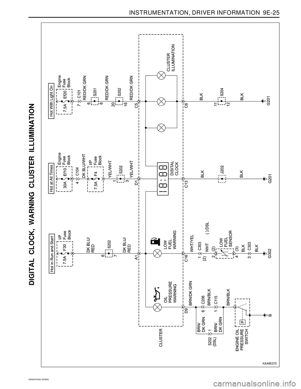
DIGITAL CLOCK, WARNING CLUSTER ILLUMINATION
KAA9E370
Page 1893 of 2053
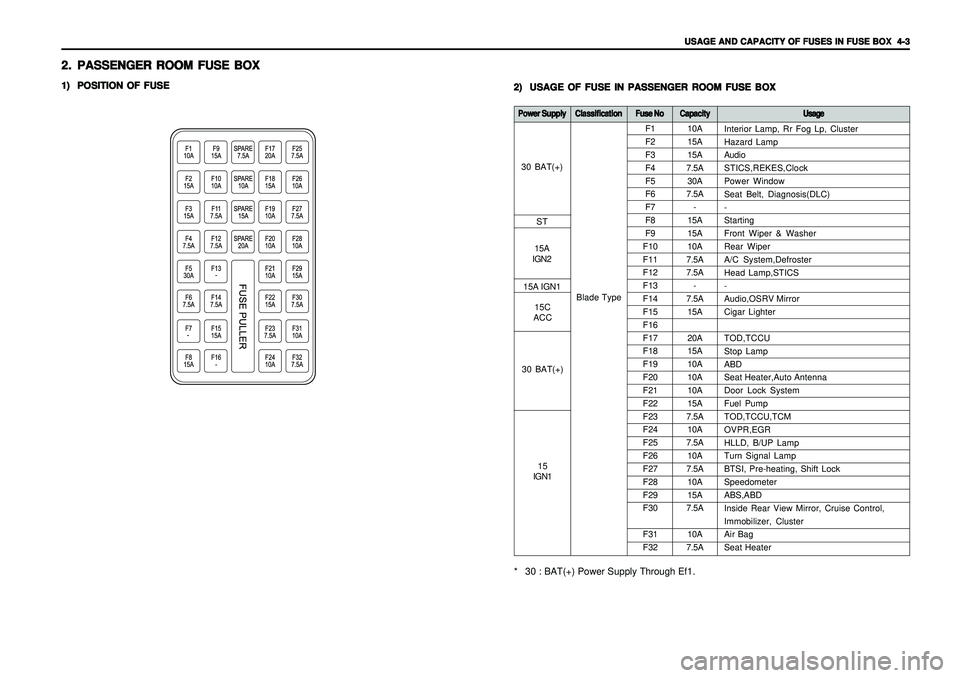
USAGE AND CAPACITY OF FUSES IN FUSE BOX USAGE AND CAPACITY OF FUSES IN FUSE BOX USAGE AND CAPACITY OF FUSES IN FUSE BOX USAGE AND CAPACITY OF FUSES IN FUSE BOX
USAGE AND CAPACITY OF FUSES IN FUSE BOX
4-3 4-34-3 4-3
4-3
2. 2.2. 2.
2.
PASSENGER ROOM FUSE BOX PASSENGER ROOM FUSE BOXPASSENGER ROOM FUSE BOX PASSENGER ROOM FUSE BOX
PASSENGER ROOM FUSE BOX1) 1)1) 1)
1)
POSITION OF FUSE POSITION OF FUSEPOSITION OF FUSE POSITION OF FUSE
POSITION OF FUSE
2) 2)2) 2)
2)
USAGE OF FUSE IN PASSENGER ROOM FUSE BOX USAGE OF FUSE IN PASSENGER ROOM FUSE BOXUSAGE OF FUSE IN PASSENGER ROOM FUSE BOX USAGE OF FUSE IN PASSENGER ROOM FUSE BOX
USAGE OF FUSE IN PASSENGER ROOM FUSE BOX
10A
15A
15A
7.5A
30A
7.5A
-
15A
15A
10A
7.5A
7.5A
-
7.5A
15A
20A
15A
10A
10A
10A
15A
7.5A
10A
7.5A
10A
7.5A
10A
15A
7.5A
10A
7.5A F1
F2
F3
F4
F5
F6
F7
F8
F9
F10
F11
F12
F13
F14
F15
F16
F17
F18
F19
F20
F21
F22
F23
F24
F25
F26
F27
F28
F29
F30
F31
F32
Power Supply Power SupplyPower Supply Power Supply
Power Supply
Classification ClassificationClassification Classification
Classification
Fuse No Fuse NoFuse No Fuse No
Fuse No
Capacity CapacityCapacity Capacity
Capacity
Usage UsageUsage Usage
Usage* 30 : BAT(+) Power Supply Through Ef1.
Blade TypeInterior Lamp, Rr Fog Lp, Cluster
Hazard Lamp
Audio
STICS,REKES,Clock
Power Window
Seat Belt, Diagnosis(DLC)
-
Starting
Front Wiper & Washer
Rear Wiper
A/C System,Defroster
Head Lamp,STICS
-
Audio,OSRV Mirror
Cigar Lighter
TOD,TCCU
Stop Lamp
ABD
Seat Heater,Auto Antenna
Door Lock System
Fuel Pump
TOD,TCCU,TCM
OVPR,EGR
HLLD, B/UP Lamp
Turn Signal Lamp
BTSI, Pre-heating, Shift Lock
Speedometer
ABS,ABD
Inside Rear View Mirror, Cruise Control,
Immobilizer, Cluster
Air Bag
Seat Heater
30 BAT(+)
ST
15A
IGN2
30 BAT(+)15C
ACC 15A IGN1
15
IGN1
Page 1898 of 2053
1) VSS(VEHICLE SPEED SENSOR), METER(SPEEDO, TACHO) & GAUGE(FUEL, TEMPERATURE)
- GASOLINE ........................................................................................................................................................... 5-96
(1) W/O EURO III .................................................................................................................................................................................... 5-96
(2) W/ EURO III ....................................................................................................................................................................................... 5-98
2) WARNING LAMP(ENGINE CHECK, AIR BAG, EBD, ABS), TCS INDICATOR............................................. 5-100
3) INDICATOR(DEFROSTER, WINTER MODE, POWR MODE, 4WD LOW, 4WD HIGH, 4WD CHECK)..... 5-102
4) WARNING LAMP (SEAT BELT, DOOR OPEN, PARKING BRAKE), INDICATOR (BATTERY CHARGING,
GLOW).................................................................................................................................................................. 5-104
5) FRONT FOG LAMP, TURN SIGNAL, HAZARD, HIGH BEAM ......................................................................... 5-106
6) DIGITAL CLOCK,WARNING (OIL PRESSURE, LOW FUEL LEVEL) CLUSTER ILLUMINATION............... 5-108
7) SELECTOR LEVER POSITION LAMP (P,R,N,D,3,2,1).................................................................................... 5-110
19. 19.19. 19.
19.
STICS(SUPER STICS(SUPER STICS(SUPER STICS(SUPER
STICS(SUPER
TIME & ALARM INTEGRA TIME & ALARM INTEGRATIME & ALARM INTEGRA TIME & ALARM INTEGRA
TIME & ALARM INTEGRA
TED CONTR TED CONTRTED CONTR TED CONTR
TED CONTR
OL SYSTEM) OL SYSTEM)OL SYSTEM) OL SYSTEM)
OL SYSTEM)
................................ ................................................................ ................................
................................
5-112 5-112 5-112 5-112
5-112
1) STICS UNIT .......................................................................................................................................................... 5-112
2) FRONT WIPER CIRCUIT.................................................................................................................................... 5-114
3) CENTRAL DOOR LOCK SYSTEM ..................................................................................................................... 5-116
4) KEYLESS, KEY REMINDER SWITCH, SIREN, CHIME BELL BUZZER ........................................................ 5-118
5) DEFROSTER........................................................................................................................................................ 5-120
6) LAMP(ROOM, DOOR COURTESY LH/RH, LUGGAGE), DOOR CONTACT SWITCH .................................. 5-122
20. 20.20. 20.
20.
SEA SEASEA SEA
SEA
T HEA T HEAT HEA T HEA
T HEA
TER TERTER TER
TER
.......................................................................................................................... .................................................................................................................................................................................................................................................... ..........................................................................................................................
..........................................................................................................................
5-124 5-124 5-124 5-124
5-124
21. 21.21. 21.
21.
ST STST ST
ST
OP LAMP OP LAMPOP LAMP OP LAMP
OP LAMP
, ,, ,
,
BTSI (BRAKE BTSI (BRAKE BTSI (BRAKE BTSI (BRAKE
BTSI (BRAKE
TRANSMISSION SHIFT INTERLOCK) TRANSMISSION SHIFT INTERLOCK)TRANSMISSION SHIFT INTERLOCK) TRANSMISSION SHIFT INTERLOCK)
TRANSMISSION SHIFT INTERLOCK)
................................... ...................................................................... ...................................
...................................
5-126 5-126 5-126 5-126
5-126
1) METAL TOP .......................................................................................................................................................... 5-126
2) SOFT TOP............................................................................................................................................................ 5-128
22. 22.22. 22.
22.
POWER WINDOW POWER WINDOWPOWER WINDOW POWER WINDOW
POWER WINDOW
..................................................................................................................... .......................................................................................................................................................................................................................................... .....................................................................................................................
.....................................................................................................................
5-130 5-130 5-130 5-130
5-130
23. 23.23. 23.
23.
ELECTRIC OSRV (OUTSIDE REAR VIEW) MIRROR ELECTRIC OSRV (OUTSIDE REAR VIEW) MIRRORELECTRIC OSRV (OUTSIDE REAR VIEW) MIRROR ELECTRIC OSRV (OUTSIDE REAR VIEW) MIRROR
ELECTRIC OSRV (OUTSIDE REAR VIEW) MIRROR
........................................................... ...................................................................................................................... ...........................................................
...........................................................
5-132 5-132 5-132 5-132
5-132
24. 24.24. 24.
24.
REAR REAR REAR REAR
REAR
WIPER & WIPER & WIPER & WIPER &
WIPER &
W WW W
W
ASHER ASHERASHER ASHER
ASHER
...................................................................................................... ............................................................................................................................................................................................................ ......................................................................................................
......................................................................................................
5-134 5-134 5-134 5-134
5-134
25. 25.25. 25.
25.
CIGARETTE LIGHTER, HORN CIGARETTE LIGHTER, HORNCIGARETTE LIGHTER, HORN CIGARETTE LIGHTER, HORN
CIGARETTE LIGHTER, HORN
................................................................................................ ................................................................................................................................................................................................ ................................................................................................
................................................................................................
5-136 5-136 5-136 5-136
5-136
26.HEAD LAMP 26.HEAD LAMP26.HEAD LAMP 26.HEAD LAMP
26.HEAD LAMP
.............................................................................................................................. ............................................................................................................................................................................................................................................................ ..............................................................................................................................
..............................................................................................................................
5-138 5-138 5-138 5-138
5-138
27. 27.27. 27.
27.
HEAD LAMP LEVELING DEVICE (HLLD) HEAD LAMP LEVELING DEVICE (HLLD)HEAD LAMP LEVELING DEVICE (HLLD) HEAD LAMP LEVELING DEVICE (HLLD)
HEAD LAMP LEVELING DEVICE (HLLD)
.............................................................................. ............................................................................................................................................................ ..............................................................................
..............................................................................
5-140 5-140 5-140 5-140
5-140
Page 2002 of 2053
5-108 5-108 5-108 5-108
5-108
ELECTRICAL WIRING DIAGRAMS ELECTRICAL WIRING DIAGRAMSELECTRICAL WIRING DIAGRAMS ELECTRICAL WIRING DIAGRAMS
ELECTRICAL WIRING DIAGRAMS6) 6)6) 6)
6)
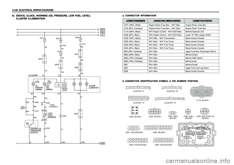
DIGITAL CLOCK, WARNING (OIL PRESSURE, LOW FUEL LEVEL) DIGITAL CLOCK, WARNING (OIL PRESSURE, LOW FUEL LEVEL)DIGITAL CLOCK, WARNING (OIL PRESSURE, LOW FUEL LEVEL) DIGITAL CLOCK, WARNING (OIL PRESSURE, LOW FUEL LEVEL)
DIGITAL CLOCK, WARNING (OIL PRESSURE, LOW FUEL LEVEL)
CLUSTER ILLUMINATION CLUSTER ILLUMINATIONCLUSTER ILLUMINATION CLUSTER ILLUMINATION
CLUSTER ILLUMINATION
a. a.a. a.
a.
CONNECTOR INFORMATION CONNECTOR INFORMATIONCONNECTOR INFORMATION CONNECTOR INFORMATION
CONNECTOR INFORMATIONb. b.b. b.
b.
CONNECTOR IDENTIFICATION SYMBOL & PIN NUMBER POSITION CONNECTOR IDENTIFICATION SYMBOL & PIN NUMBER POSITIONCONNECTOR IDENTIFICATION SYMBOL & PIN NUMBER POSITION CONNECTOR IDENTIFICATION SYMBOL & PIN NUMBER POSITION
CONNECTOR IDENTIFICATION SYMBOL & PIN NUMBER POSITION
CLUSTER "B"
CLUSTER "A"
CLUSTER "C" CLUSTER "D"
C115 (BLACK)
C206 (BLACK)C302 (BLACK)C303 (DSL)
(BLACK)C303 (GSL)
(BLACK)C303 (GSL:EURO III)
(BLACK)
S202 (BLACK)
S203 (COLORLESS) S204 (COLORLESS)
C101 (19Pin, White)
C104 (8Pin, Colorless)
C115 (40Pin, Black)
C206 (6Pin, Black)
C302 (10Pin, Black)
C303 (3Pin, Black)
C303 (4Pin, Black)
C303 (6Pin, Black)
S201 (8Pin, Colorless)
S202 (20Pin, Black)
S203 (14Pin, Colorless)
S204 (14Pin, Colorless)
J202
G201
G302CONNECTOR(NUMBER) CONNECTOR(NUMBER)CONNECTOR(NUMBER) CONNECTOR(NUMBER)
CONNECTOR(NUMBER)
CONNECTING. WIRING HARNESS CONNECTING. WIRING HARNESSCONNECTING. WIRING HARNESS CONNECTING. WIRING HARNESS
CONNECTING. WIRING HARNESS
CONNECTOR POSITION CONNECTOR POSITIONCONNECTOR POSITION CONNECTOR POSITION
CONNECTOR POSITION
Engine Room Fuse Box - W/H Main
Engine Room Fuse Box - W/H Main
W/H Engine Control - W/H ECM Main
W/H Engine Control - W/H ECM Main
W/H Main - W/H Transmission
W/H Main - W/H Fuel Pump
W/H Main - W/H Fuel Pump
W/H Main - W/H Fuel Pump
W/H Main
W/H Main
W/H Main
W/H Main
W/H Main
W/H Main
W/H MainEngine Room Fuse Box
Engine Room Fuse Box
Behind Hydraulic Unit
Lower "A" Piller (Upper ECM)
Below Center Console
Below Center Console
Below Center Console
Below Center Console
Upper Fuse Box (Passenger Room)
Behind Cluster
Behind 4WD Switch
Behind Audio
Behind Cluster
Upper Front Left Leg Room
Below Center Console
S201 (COLORLESS)