1997 SSANGYONG KORANDO ignition
[x] Cancel search: ignitionPage 1022 of 2053
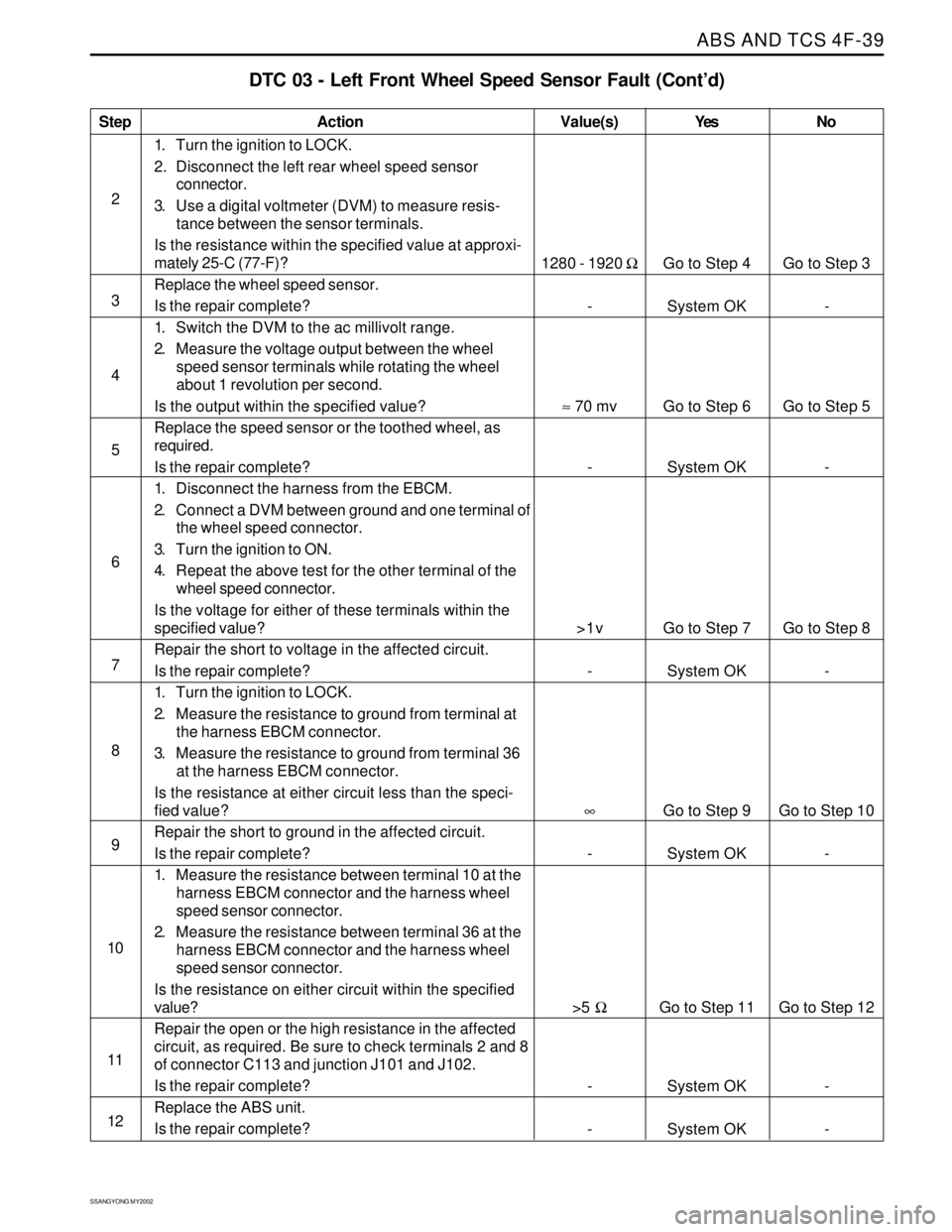
ABS AND TCS 4F-39
SSANGYONG MY2002
Step
2
3
4
5
6
7
8
9
10
11
12
DTC 03 - Left Front Wheel Speed Sensor Fault (Cont’d)
Action
Go to Step 4
System OK
Go to Step 6
System OK
Go to Step 7
System OK
Go to Step 9
System OK
Go to Step 11
System OK
System OKGo to Step 3
-
Go to Step 5
-
Go to Step 8
-
Go to Step 10
-
Go to Step 12
-
- 1280 - 1920 Ω
-
≈ 70 mv
-
>1v
-
∞
-
>5 Ω
-
-
1. Turn the ignition to LOCK.
2. Disconnect the left rear wheel speed sensor
connector.
3. Use a digital voltmeter (DVM) to measure resis-
tance between the sensor terminals.
Is the resistance within the specified value at approxi-
mately 25-C (77-F)?
Replace the wheel speed sensor.
Is the repair complete?
1. Switch the DVM to the ac millivolt range.
2. Measure the voltage output between the wheel
speed sensor terminals while rotating the wheel
about 1 revolution per second.
Is the output within the specified value?
Replace the speed sensor or the toothed wheel, as
required.
Is the repair complete?
1. Disconnect the harness from the EBCM.
2. Connect a DVM between ground and one terminal of
the wheel speed connector.
3. Turn the ignition to ON.
4. Repeat the above test for the other terminal of the
wheel speed connector.
Is the voltage for either of these terminals within the
specified value?
Repair the short to voltage in the affected circuit.
Is the repair complete?
1. Turn the ignition to LOCK.
2. Measure the resistance to ground from terminal at
the harness EBCM connector.
3. Measure the resistance to ground from terminal 36
at the harness EBCM connector.
Is the resistance at either circuit less than the speci-
fied value?
Repair the short to ground in the affected circuit.
Is the repair complete?
1. Measure the resistance between terminal 10 at the
harness EBCM connector and the harness wheel
speed sensor connector.
2. Measure the resistance between terminal 36 at the
harness EBCM connector and the harness wheel
speed sensor connector.
Is the resistance on either circuit within the specified
value?
Repair the open or the high resistance in the affected
circuit, as required. Be sure to check terminals 2 and 8
of connector C113 and junction J101 and J102.
Is the repair complete?
Replace the ABS unit.
Is the repair complete?
Value(s) Yes No
Page 1024 of 2053
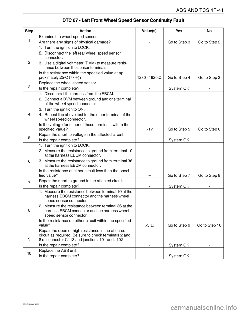
ABS AND TCS 4F-41
SSANGYONG MY2002
Step
1
2
3
4
5
6
7
8
9
10
DTC 07 - Left Front Wheel Speed Sensor Continuity Fault
Action
Go to Step 3
Go to Step 4
System OK
Go to Step 5
System OK
Go to Step 7
System OK
Go to Step 9
System OK
System OKGo to Step 2
Go to Step 3
-
Go to Step 6
-
Go to Step 8
-
Go to Step 10
-
- -
1280 - 1920 Ω
-
>1v
-
∞
-
>5 Ω
-
-
Examine the wheel speed sensor.
Are there any signs of physical damage?
1. Turn the ignition to LOCK.
2. Disconnect the left rear wheel speed sensor
connector.
3. Use a digital voltmeter (DVM) to measure resis-
tance between the sensor terminals.
Is the resistance within the specified value at ap-
proximately 25-C (77-F)?
Replace the wheel speed sensor.
Is the repair complete?
1. Disconnect the harness from the EBCM.
2. Connect a DVM between ground and one terminal
of the wheel speed connector.
3. Turn the ignition to ON.
4. Repeat the above test for the other terminal of the
wheel speed connector.
Is the voltage for either of these terminals within the
specified value?
Repair the short to voltage in the affected circuit.
Is the repair complete?
1. Turn the ignition to LOCK.
2. Measure the resistance to ground from terminal 10
at the harness EBCM connector.
3. Measure the resistance to ground from terminal 36
at the harness EBCM connector.
Is the resistance at either circuit less than the speci-
fied value?
Repair the short to ground in the affected circuit.
Is the repair complete?
1. Measure the resistance between terminal 10 at the
harness EBCM connector and the harness wheel
speed sensor connector.
2. Measure the resistance between terminal 36 at the
harness EBCM connector and the harness wheel
speed sensor connector.
Is the resistance on either circuit within the specified
value?
Repair the open or high resistance in the affected
circuit as required. Be sure to check terminals 2 and
8 of connector C113 and junction J101 and J102.
Is the repair complete?
Replace the ABS unit.
Is the repair complete?
Value(s) Yes No
Page 1026 of 2053
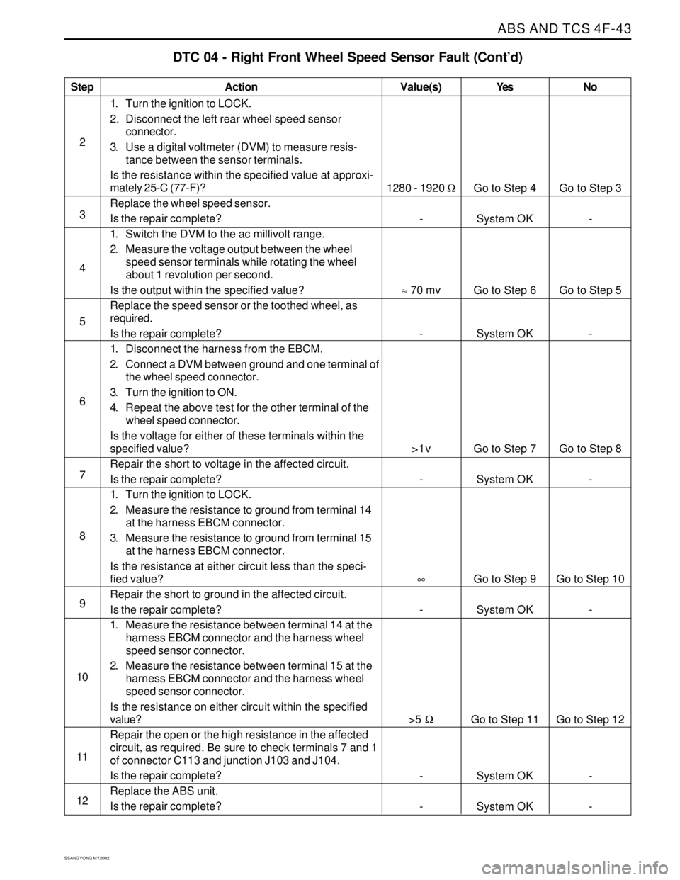
ABS AND TCS 4F-43
SSANGYONG MY2002
Step
2
3
4
5
6
7
8
9
10
11
12
DTC 04 - Right Front Wheel Speed Sensor Fault (Cont’d)
Action
Go to Step 4
System OK
Go to Step 6
System OK
Go to Step 7
System OK
Go to Step 9
System OK
Go to Step 11
System OK
System OKGo to Step 3
-
Go to Step 5
-
Go to Step 8
-
Go to Step 10
-
Go to Step 12
-
- 1280 - 1920 Ω
-
≈ 70 mv
-
>1v
-
∞
-
>5 Ω
-
-
1. Turn the ignition to LOCK.
2. Disconnect the left rear wheel speed sensor
connector.
3. Use a digital voltmeter (DVM) to measure resis-
tance between the sensor terminals.
Is the resistance within the specified value at approxi-
mately 25-C (77-F)?
Replace the wheel speed sensor.
Is the repair complete?
1. Switch the DVM to the ac millivolt range.
2. Measure the voltage output between the wheel
speed sensor terminals while rotating the wheel
about 1 revolution per second.
Is the output within the specified value?
Replace the speed sensor or the toothed wheel, as
required.
Is the repair complete?
1. Disconnect the harness from the EBCM.
2. Connect a DVM between ground and one terminal of
the wheel speed connector.
3. Turn the ignition to ON.
4. Repeat the above test for the other terminal of the
wheel speed connector.
Is the voltage for either of these terminals within the
specified value?
Repair the short to voltage in the affected circuit.
Is the repair complete?
1. Turn the ignition to LOCK.
2. Measure the resistance to ground from terminal 14
at the harness EBCM connector.
3. Measure the resistance to ground from terminal 15
at the harness EBCM connector.
Is the resistance at either circuit less than the speci-
fied value?
Repair the short to ground in the affected circuit.
Is the repair complete?
1. Measure the resistance between terminal 14 at the
harness EBCM connector and the harness wheel
speed sensor connector.
2. Measure the resistance between terminal 15 at the
harness EBCM connector and the harness wheel
speed sensor connector.
Is the resistance on either circuit within the specified
value?
Repair the open or the high resistance in the affected
circuit, as required. Be sure to check terminals 7 and 1
of connector C113 and junction J103 and J104.
Is the repair complete?
Replace the ABS unit.
Is the repair complete?
Value(s) Yes No
Page 1028 of 2053
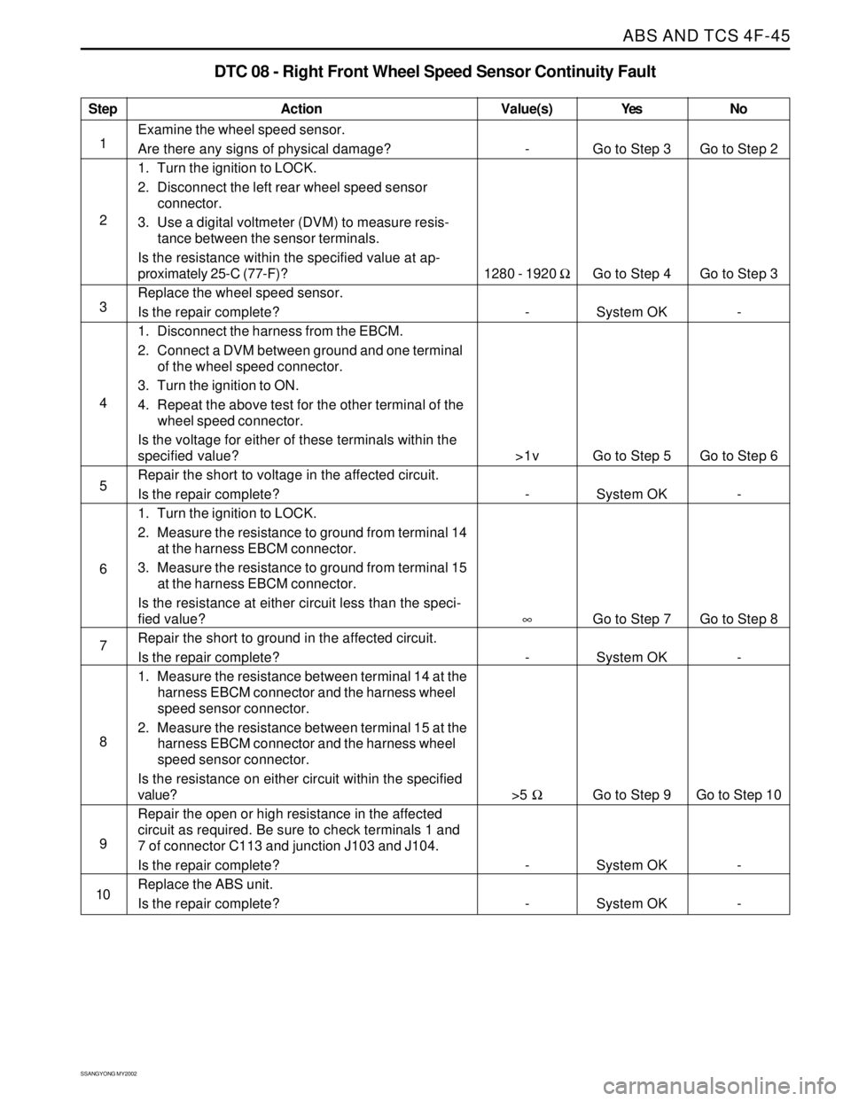
ABS AND TCS 4F-45
SSANGYONG MY2002
Step
1
2
3
4
5
6
7
8
9
10
DTC 08 - Right Front Wheel Speed Sensor Continuity Fault
Action
Go to Step 3
Go to Step 4
System OK
Go to Step 5
System OK
Go to Step 7
System OK
Go to Step 9
System OK
System OKGo to Step 2
Go to Step 3
-
Go to Step 6
-
Go to Step 8
-
Go to Step 10
-
- -
1280 - 1920 Ω
-
>1v
-
∞
-
>5 Ω
-
-
Examine the wheel speed sensor.
Are there any signs of physical damage?
1. Turn the ignition to LOCK.
2. Disconnect the left rear wheel speed sensor
connector.
3. Use a digital voltmeter (DVM) to measure resis-
tance between the sensor terminals.
Is the resistance within the specified value at ap-
proximately 25-C (77-F)?
Replace the wheel speed sensor.
Is the repair complete?
1. Disconnect the harness from the EBCM.
2. Connect a DVM between ground and one terminal
of the wheel speed connector.
3. Turn the ignition to ON.
4. Repeat the above test for the other terminal of the
wheel speed connector.
Is the voltage for either of these terminals within the
specified value?
Repair the short to voltage in the affected circuit.
Is the repair complete?
1. Turn the ignition to LOCK.
2. Measure the resistance to ground from terminal 14
at the harness EBCM connector.
3. Measure the resistance to ground from terminal 15
at the harness EBCM connector.
Is the resistance at either circuit less than the speci-
fied value?
Repair the short to ground in the affected circuit.
Is the repair complete?
1. Measure the resistance between terminal 14 at the
harness EBCM connector and the harness wheel
speed sensor connector.
2. Measure the resistance between terminal 15 at the
harness EBCM connector and the harness wheel
speed sensor connector.
Is the resistance on either circuit within the specified
value?
Repair the open or high resistance in the affected
circuit as required. Be sure to check terminals 1 and
7 of connector C113 and junction J103 and J104.
Is the repair complete?
Replace the ABS unit.
Is the repair complete?
Value(s) Yes No
Page 1030 of 2053
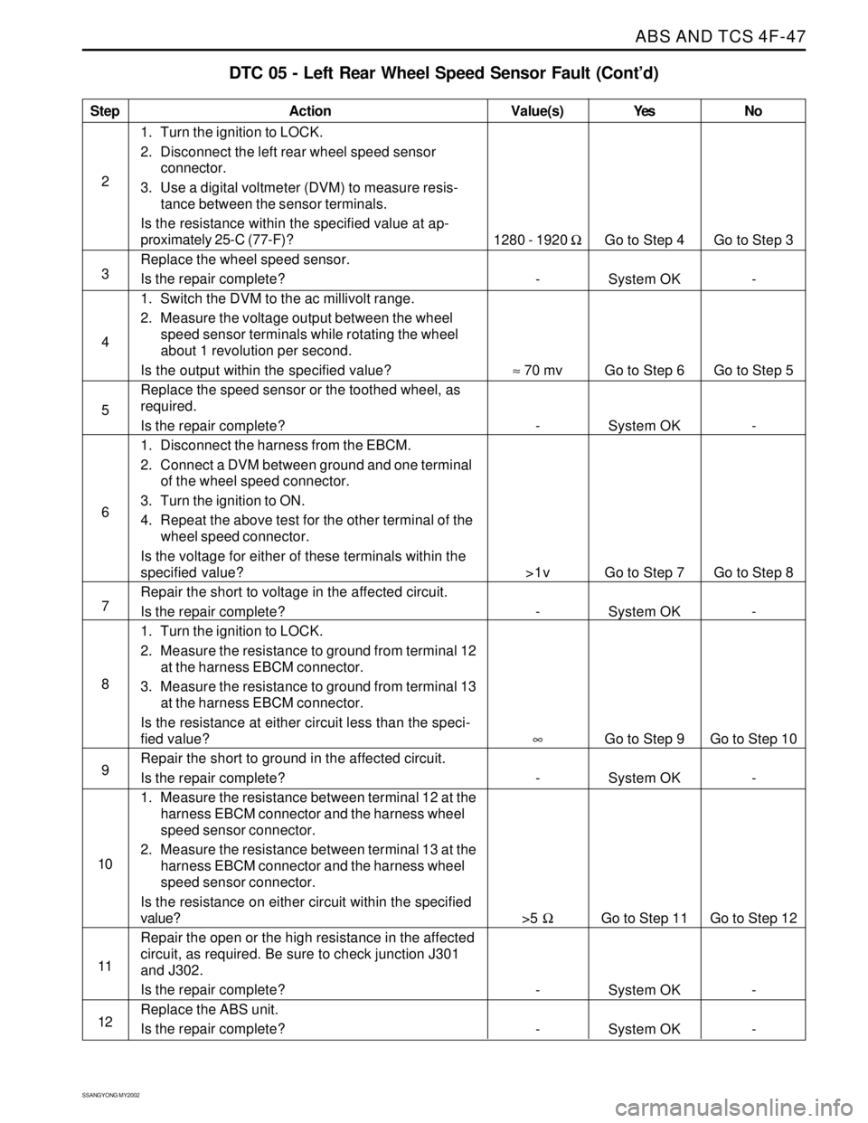
ABS AND TCS 4F-47
SSANGYONG MY2002
Step
2
3
4
5
6
7
8
9
10
11
12
DTC 05 - Left Rear Wheel Speed Sensor Fault (Cont’d)
Action
Go to Step 4
System OK
Go to Step 6
System OK
Go to Step 7
System OK
Go to Step 9
System OK
Go to Step 11
System OK
System OKGo to Step 3
-
Go to Step 5
-
Go to Step 8
-
Go to Step 10
-
Go to Step 12
-
- 1280 - 1920 Ω
-
≈ 70 mv
-
>1v
-
∞
-
>5 Ω
-
-
1. Turn the ignition to LOCK.
2. Disconnect the left rear wheel speed sensor
connector.
3. Use a digital voltmeter (DVM) to measure resis-
tance between the sensor terminals.
Is the resistance within the specified value at ap-
proximately 25-C (77-F)?
Replace the wheel speed sensor.
Is the repair complete?
1. Switch the DVM to the ac millivolt range.
2. Measure the voltage output between the wheel
speed sensor terminals while rotating the wheel
about 1 revolution per second.
Is the output within the specified value?
Replace the speed sensor or the toothed wheel, as
required.
Is the repair complete?
1. Disconnect the harness from the EBCM.
2. Connect a DVM between ground and one terminal
of the wheel speed connector.
3. Turn the ignition to ON.
4. Repeat the above test for the other terminal of the
wheel speed connector.
Is the voltage for either of these terminals within the
specified value?
Repair the short to voltage in the affected circuit.
Is the repair complete?
1. Turn the ignition to LOCK.
2. Measure the resistance to ground from terminal 12
at the harness EBCM connector.
3. Measure the resistance to ground from terminal 13
at the harness EBCM connector.
Is the resistance at either circuit less than the speci-
fied value?
Repair the short to ground in the affected circuit.
Is the repair complete?
1. Measure the resistance between terminal 12 at the
harness EBCM connector and the harness wheel
speed sensor connector.
2. Measure the resistance between terminal 13 at the
harness EBCM connector and the harness wheel
speed sensor connector.
Is the resistance on either circuit within the specified
value?
Repair the open or the high resistance in the affected
circuit, as required. Be sure to check junction J301
and J302.
Is the repair complete?
Replace the ABS unit.
Is the repair complete?
Value(s) Yes No
Page 1032 of 2053
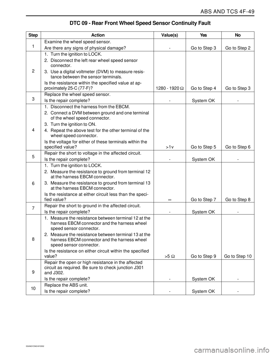
ABS AND TCS 4F-49
SSANGYONG MY2002
Step
1
2
3
4
5
6
7
8
9
10
DTC 09 - Rear Front Wheel Speed Sensor Continuity Fault
Action
Go to Step 3
Go to Step 4
System OK
Go to Step 5
System OK
Go to Step 7
System OK
Go to Step 9
System OK
System OKGo to Step 2
Go to Step 3
-
Go to Step 6
-
Go to Step 8
-
Go to Step 10
-
- -
1280 - 1920 Ω
-
>1v
-
∞
-
>5 Ω
-
-
Examine the wheel speed sensor.
Are there any signs of physical damage?
1. Turn the ignition to LOCK.
2. Disconnect the left rear wheel speed sensor
connector.
3. Use a digital voltmeter (DVM) to measure resis-
tance between the sensor terminals.
Is the resistance within the specified value at ap-
proximately 25-C (77-F)?
Replace the wheel speed sensor.
Is the repair complete?
1. Disconnect the harness from the EBCM.
2. Connect a DVM between ground and one terminal
of the wheel speed connector.
3. Turn the ignition to ON.
4. Repeat the above test for the other terminal of the
wheel speed connector.
Is the voltage for either of these terminals within the
specified value?
Repair the short to voltage in the affected circuit.
Is the repair complete?
1. Turn the ignition to LOCK.
2. Measure the resistance to ground from terminal 12
at the harness EBCM connector.
3. Measure the resistance to ground from terminal 13
at the harness EBCM connector.
Is the resistance at either circuit less than the speci-
fied value?
Repair the short to ground in the affected circuit.
Is the repair complete?
1. Measure the resistance between terminal 12 at the
harness EBCM connector and the harness wheel
speed sensor connector.
2. Measure the resistance between terminal 13 at the
harness EBCM connector and the harness wheel
speed sensor connector.
Is the resistance on either circuit within the specified
value?
Repair the open or high resistance in the affected
circuit as required. Be sure to check junction J301
and J302.
Is the repair complete?
Replace the ABS unit.
Is the repair complete?
Value(s) Yes No
Page 1034 of 2053
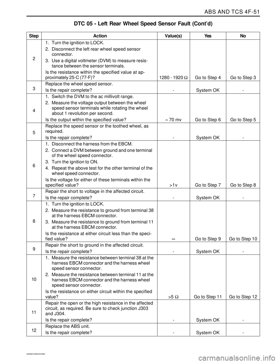
ABS AND TCS 4F-51
SSANGYONG MY2002
Step
2
3
4
5
6
7
8
9
10
11
12
DTC 05 - Left Rear Wheel Speed Sensor Fault (Cont’d)
Action
Go to Step 4
System OK
Go to Step 6
System OK
Go to Step 7
System OK
Go to Step 9
System OK
Go to Step 11
System OK
System OKGo to Step 3
-
Go to Step 5
-
Go to Step 8
-
Go to Step 10
-
Go to Step 12
-
- 1280 - 1920 Ω
-
≈ 70 mv
-
>1v
-
∞
-
>5 Ω
-
-
1. Turn the ignition to LOCK.
2. Disconnect the left rear wheel speed sensor
connector.
3. Use a digital voltmeter (DVM) to measure resis-
tance between the sensor terminals.
Is the resistance within the specified value at ap-
proximately 25-C (77-F)?
Replace the wheel speed sensor.
Is the repair complete?
1. Switch the DVM to the ac millivolt range.
2. Measure the voltage output between the wheel
speed sensor terminals while rotating the wheel
about 1 revolution per second.
Is the output within the specified value?
Replace the speed sensor or the toothed wheel, as
required.
Is the repair complete?
1. Disconnect the harness from the EBCM.
2. Connect a DVM between ground and one terminal
of the wheel speed connector.
3. Turn the ignition to ON.
4. Repeat the above test for the other terminal of the
wheel speed connector.
Is the voltage for either of these terminals within the
specified value?
Repair the short to voltage in the affected circuit.
Is the repair complete?
1. Turn the ignition to LOCK.
2. Measure the resistance to ground from terminal 38
at the harness EBCM connector.
3. Measure the resistance to ground from terminal 11
at the harness EBCM connector.
Is the resistance at either circuit less than the speci-
fied value?
Repair the short to ground in the affected circuit.
Is the repair complete?
1. Measure the resistance between terminal 38 at the
harness EBCM connector and the harness wheel
speed sensor connector.
2. Measure the resistance between terminal 11 at the
harness EBCM connector and the harness wheel
speed sensor connector.
Is the resistance on either circuit within the specified
value?
Repair the open or the high resistance in the affected
circuit, as required. Be sure to check junction J303
and J304.
Is the repair complete?
Replace the ABS unit.
Is the repair complete?
Value(s) Yes No
Page 1036 of 2053
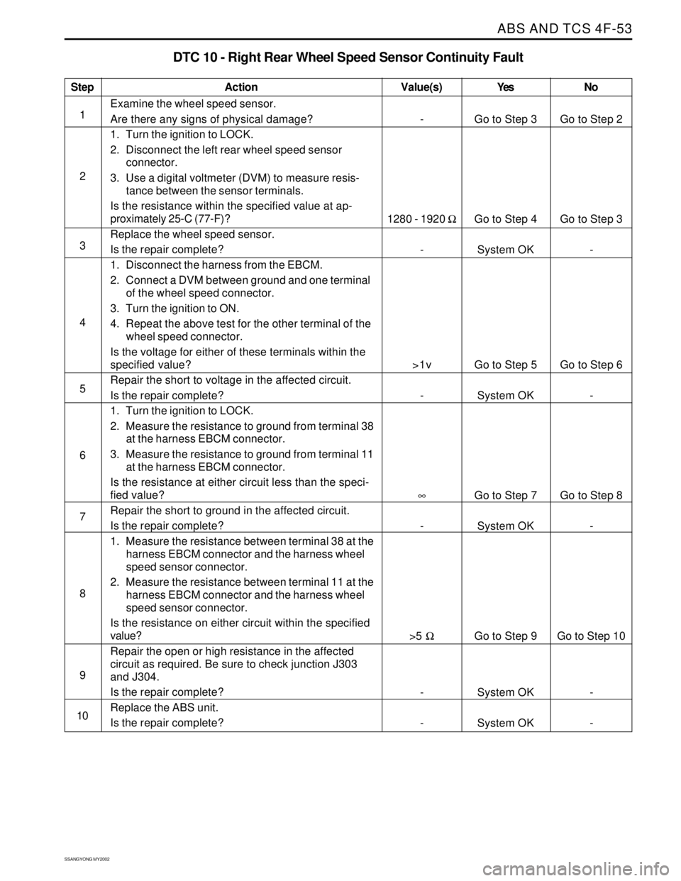
ABS AND TCS 4F-53
SSANGYONG MY2002
Step
1
2
3
4
5
6
7
8
9
10
DTC 10 - Right Rear Wheel Speed Sensor Continuity Fault
Action
Go to Step 3
Go to Step 4
System OK
Go to Step 5
System OK
Go to Step 7
System OK
Go to Step 9
System OK
System OKGo to Step 2
Go to Step 3
-
Go to Step 6
-
Go to Step 8
-
Go to Step 10
-
- -
1280 - 1920 Ω
-
>1v
-
∞
-
>5 Ω
-
-
Examine the wheel speed sensor.
Are there any signs of physical damage?
1. Turn the ignition to LOCK.
2. Disconnect the left rear wheel speed sensor
connector.
3. Use a digital voltmeter (DVM) to measure resis-
tance between the sensor terminals.
Is the resistance within the specified value at ap-
proximately 25-C (77-F)?
Replace the wheel speed sensor.
Is the repair complete?
1. Disconnect the harness from the EBCM.
2. Connect a DVM between ground and one terminal
of the wheel speed connector.
3. Turn the ignition to ON.
4. Repeat the above test for the other terminal of the
wheel speed connector.
Is the voltage for either of these terminals within the
specified value?
Repair the short to voltage in the affected circuit.
Is the repair complete?
1. Turn the ignition to LOCK.
2. Measure the resistance to ground from terminal 38
at the harness EBCM connector.
3. Measure the resistance to ground from terminal 11
at the harness EBCM connector.
Is the resistance at either circuit less than the speci-
fied value?
Repair the short to ground in the affected circuit.
Is the repair complete?
1. Measure the resistance between terminal 38 at the
harness EBCM connector and the harness wheel
speed sensor connector.
2. Measure the resistance between terminal 11 at the
harness EBCM connector and the harness wheel
speed sensor connector.
Is the resistance on either circuit within the specified
value?
Repair the open or high resistance in the affected
circuit as required. Be sure to check junction J303
and J304.
Is the repair complete?
Replace the ABS unit.
Is the repair complete?
Value(s) Yes No