1997 SSANGYONG KORANDO ignition
[x] Cancel search: ignitionPage 504 of 2053

1F2 -- 86 M161 ENGINE CONTROLS
D AEW OO M Y_2000
ENGINE CONTROL MODULE
YAA1F830
The Engine Control Module (ECM), located inside the right side kick panel, is the control center of the fuel injection
system. It constantly looks at the information from various sensors and controls the systems that affect the vehicle’s
performance. Engine rpm and air mass are used to measure the air intake quantity resulting in fuel injection metering.
The ECM also performs the diagnostic functions of the system. It can recognize operational problems, store failure
code(s) which identify the problem areas to aid the technician in making repairs.
There are no serviceable parts in the ECM. The calibrations are stored in the ECM in the Programmable Read Only
Memory (PROM).
The ECM supplies either 5 or 12 volts to power the sensors or switches. This is done through resistance in the ECM
which are so high in value that a test light will not come ON when connected to the circuit. In some cases, even an
ordinary shop voltmeter will not give and accurate reading because its resistance is too low. You must use a digital
voltmeter with a 10 Mohm input impedance to get accurate voltage readings. The ECM controls output circuits such as
the ignition coils, the fuel injectors, the fuel pump relay, the camshaft actuator, the canister purge valve, etc., by con-
trolling the ground circuit.
Page 512 of 2053

1F2 -- 94 M161 ENGINE CONTROLS
D AEW OO M Y_2000
IMMOBILIZER
KAB1F360
Failure
CodeDescriptionTrouble AreaMaintenance Hint
25Communication with
transponder missingWhen missing the
transponder signal
DInspection the Engine Control Module
(ECM) pin 13, 14 about short circuit or
open with bad contact
DInspection the power source or ground
short circuit or open of immobilizer unit
DInspection the transponder condition
(broken etc.)
DInspection the ECM
141Unprogramed ECM with
immobilizer
When malfunction of
immobilizer
Required immobilizer
encoding, no paired condition
of immobilizer even through
start trial
DFulfill the immobilizer pairing
Circuit Description
Immobilizer is a device disabling vehicle ignition unless a specific key is used and designed to help prevent vehicle
theft.
Immobilizer is comprised of two devices, a key with encoded transponder and ECM with the same encoding of the
transponder. When a key is inserted into the hole to start vehicle and turned to ON, the ECM reads and decodes the
transponder code and, if the same, starts the engine, it is called immobilizer. It means immobilizersystem disables
starting by stopping fuel supply if the code in the transponder does not match the code stored in ECM each other.
Page 516 of 2053

1F2 -- 98 M161 ENGINE CONTROLS
D AEW OO M Y_2000
YAA1F180
14. Turn the roll over valves counterclockwise at an
angle of 90 degrees.
15. Turn the lock ring counterclockwise.
16. Remove and discard the gasket.
17. Installation should follow the removal procedure in
the reverse order.
YAA1F700
FUEL PRESSURE REGULATOR
Removal and Installation Procedure
1. Disconnect the negative battery cable.
2. Remove the fuel pressure test connector.
Installation Notice
Tightening Torque
25 NSm (18 Ib-ft)
YAA1F720
Caution: The fuel system is under pressure. To
avoid fuel spillage and the risk of personal injury or
fire, it is necessary to relieve the fuel system pres -
sure before disconnecting the fuel lines.
3. Relieve the fuel pressure in fuel supply system by
pressing the service valve.
YAA1F730
4. Disconnect the vacuum hose.
5. Disconnect the circlip and remove the fuel pressure
regulator.
6. Apply the oil to O-ring lightly and then replace it.
7. Perform a leak test of the fuel pressure regulator
with the engine off and the ignition on.
8. Installation should follow the removal procedure in
the reverse order.
Page 524 of 2053

D AEW OO M Y_2000
SECTION 1G2
M161 ENGINE INTAKE & EXHAUST
CAUTION: Disconnect the negative battery cable before removing or installing any electrical unit or when a
tool or equipment could easily come in contact with exposed electrical terminals. Disconnecting this cable
will help prevent personal injury and damage to the vehicle. The ignition must also be in LOCK unless other -
wise noted.
TABLE OF CONTENTS
Specifications 1G2 -- 2...........................
Fastener Tightening Specifications 1G2 -- 2.........
Maintenance and Repair 1G2 -- 3..................
On-- Vehicle Service 1G2-- 3........................
Air Cleaner 1G2-- 3.............................
Air Intake Shield 1G2-- 5.........................Intake Air Duct 1G2--6..........................
Intake Manifold 1G2--8.........................
Exhaust Manifold 1G2-- 10.......................
Removal and Installation of Exhaust
System 1G2-- 12.............................
Page 536 of 2053

D AEW OO M Y_2000
SECTION 1
ENGINE
SECTION 1A3 (OM600 ENGINE)
GENERAL ENGINE INFORMATION
TABLE OF CONTENTS
Specifications 1A3 -- 1............................
Engine Specifications 1A3-- 1.....................
Sectional View 1A3 -- 3............................
OM662LA Engine 1A3-- 3........................
OM661LA Engine 1A3-- 5........................
Performance Curve 1A3-- 7........................
OM662LA Engine 1A3-- 7........................
OM661LA Engine 1A3-- 8........................
Special Tools 1A3 -- 9.............................Special Tools Table 1A3-- 9.......................
Diagnosis 1A3 -- 10................................
Oil Leak Diagnosis 1A3-- 10.......................
Compression Pressure Test 1A3-- 11..............
Cylinder Pressure Leakage Test 1A3-- 13...........
General Information 1A3 -- 15......................
Cleanliness and Care 1A3 -- 15....................
On-- Engine Service 1A3-- 15......................
SPECIFICATIONS
ENGINE SPECIFICATIONS
ApplicationOM662LAOM661LA
Engine TypeFour -- Stroke DieselFour -- Stroke Diesel
Displacement (CC)28742299
Cylinder (Bore x Stroke)(mm)89 x 92.489 x 92.4
Fuel Injection / Ignition SystemPES 5 M55 C320 RS 168PES 5 M55 C320 RS 167
Compression Ratio22 :122 :1
Number of Cylinders54
Camshaft Valve ArrangementSOHCSOHC
Camshaft Drive TypeChain -- DriveChain-- Drive
Max. Output (ps/rpm)120 / 4000101 / 4000
Max. Torque (kgSm/rpm)25.5 / 400021.5 / 2400
Firing Order1--2--4--5--31--3--4--2
Injection TimingBTDC 18_±10_BTDC 18_±10_
Valve Timing
(t2lift)
IntakeOpen/CloseAT DC 11 . 3 3_/ ABDC 17_AT DC 11 . 3 3_/ ABDC 17_g
(at 2mm lift)ExhaustOpen/CloseBBDC 28_/ BTDC 15.25_BBDC 28_/ BTDC 15.25_
Valve Clearance AdjustmentAutomatic ControlAutomatic Control
Page 550 of 2053

GENERAL ENGINE INFORMATION 1A3 -- 15
D AEW OO M Y_2000
GENERAL INFORMATION
CLEANLINESS AND CARE
An automobile engine is a combination of many ma-
chined, honed, polished and lapped surfaces with toler-
ances that are measured in the ten-- thousanths of an
inch. When any internal engine parts are serviced, care
and cleanliness are important. A liberal coating of en-
igne oil should be applied to friction areas during assem-
bly, to protect and lubricate the surfaces on initial
operation. Proper cleaning and protection of machined
surfaces and friction areas is part fo the repair proce-
dure. This is considered standard shop practice even if
not specifically stated.
Whenever valve train components are removed for ser-
vice, they should be kept in order. They should be
installed in the same locations, and with the same mat-
ing surfaces, as when they were removed.
Battery cables should be disconnected before any major
work is performed on the engine. Failure to disconnectcables may result in damage to wire harness or other
electrical parts.
ON-- ENGINE SERVICE
Caution: Disconnect the negative battery cable be -
fore removing or installing any electrical unit, or
when a tool or equipment could easily come in con-
tact with exposed electrical terminals. Disconnect -
ing this cable will help prevent personal injury and
damage to the vehicle. The ignition must also be in
LOCK unless otherwise noted.
Notice:Any time the air cleaner is removed, the intake
opening should be covered. Thiswill protect against ac-
cidental entrance of foreign material, which could follow
the intake passage into the cylinder and cause exten-
sive damage when the engine is started.
Page 551 of 2053

D AEW OO M Y_2000
SECTION 1B3
OM600 ENGINE MECHANICAL
CAUTION: Disconnect the negative battery cable before removing or installing any electrical unit or when a
tool or equipment could easily come in contact with exposed electrical terminals. Disconnecting this cable
will help prevent personal injury and damage to the vehicle. The ignition must also be in LOCK unless
otherwise noted.
TABLE OF CONTENTS
Specifications 1B3 -- 2............................
Fastener Tightening Specifications 1B3 -- 2..........
Special Tools 1B3 -- 4.............................
Special Tools Table 1B3-- 4.......................
Maintenance and Repair 1B3 -- 12..................
On-- Vehicle Service 1B3-- 12........................
Engine Assembly 1B3-- 12........................
Poly V-- Belt 1B3 -- 21.............................
Tensioning Device 1B3-- 23.......................
Poly V-- Belt Alignment & Inspection 1B3-- 26........
Prechamber 1B3-- 29............................
Milling of Prechamber Sealing Surface 1B3 -- 32.....
TDC (TDC Sensor Bracket) Setting 1B3 -- 35........
Cylinder Head 1B3-- 37...........................
Timing Case Cover 1B3 -- 63......................
Crankshaft End Cover 1B3-- 71...................
Vibration Damper and Hub 1B3-- 74...............
Crankshaft Front Radial Seal 1B3-- 80.............
Crankshaft Ball Bearing 1B3-- 82..................
Crankshaft 1B3-- 83.............................
Flywheel 1B3 -- 93...............................
Machining of Flywheel 1B3-- 97...................
Flywheel Ring Gear 1B3 -- 98......................
Hydraulic Valve Clearance Compensation
Element Check 1B3-- 101.........................
Valve Tappets 1B3-- 103..........................
Valve Spring Check 1B3-- 105.....................Valve Springs (Cylinder Head Removed) 1B3-- 106..
Valve Springs (Cylinder Head Installed) 1B3-- 109...
Valve Stem Seals 1B3-- 112......................
Check and Replacement of Valve Guides 1B3-- 116..
Valve Seat Rings 1B3-- 122.......................
Check and Machining of Valves 1B3-- 127..........
Machining of Valve Seat 1B3-- 132.................
Camshaft Timing Test 1B3-- 137...................
Camshaft 1B3-- 139.............................
Chain Tensioner 1B3-- 145........................
Timing Chain 1B3-- 147...........................
Tensioning Rail 1B3-- 151.........................
Cylinder Head Guide Rail 1B3-- 152................
Timing Case Cover Guide Rail 1B3-- 156...........
Crankshaft Sprocket 1B3-- 158....................
Piston 1B3-- 163.................................
Oil Filter 1B3-- 169...............................
Oil Pan 1B3-- 171................................
Oil Spray Nozzle 1B3-- 174.......................
Oil Pump 1B3-- 175..............................
Unit Repair 1B3 -- 177............................
Cylinder Head Pressure Leakage Test 1B3-- 177....
Facing Cylinder Head Mating Surface 1B3 -- 178.....
Replacement of Crankcase Core Plug 1B3-- 180.....
Facing Crankcase Contacting Surface 1B3 -- 182....
Oil Gallery Steel Ball 1B3-- 183....................
Cylinder Bore Measurement 1B3-- 187.............
Page 737 of 2053

D AEW OO M Y_2000
SECTION 1D3
OM600 ENGINE COOLING
Caution: Disconnect the negative battery cable before removing or installing any electrical unit or when a
tool or equipment could easily come in contact with exposed electrical terminals. Disconnecting this cable
will help prevent personal injury and damage to the vehicle. The ignition must also be in LOCK unless other -
wise noted.
TABLE OF CONTENTS
Specifications 1D3 -- 1............................
General Specifications 1D3-- 1....................
Fastener Tightening Specifications 1D3 -- 1..........
Diagnosis 1D3 -- 2.................................
Cooling Circulation 1D3 -- 2........................
Thermostat Operation 1D3 -- 3....................
Cooling System Leakage Test 1D3-- 4..............
Maintenance and Repair 1D3 -- 5...................On-- Vehicle Service 1D3-- 5.........................
Drain and Filling of Coolant 1D3 -- 5................
Wat er Pum p 1D3 -- 6.............................
Water Pump Housing 1D3-- 8.....................
Cooling Fan Clutch 1D3 -- 10......................
Radiator 1D3-- 12................................
Cooling Sub-- System 1D3-- 14.....................
Thermostat 1D3 -- 16.............................
SPECIFICATIONS
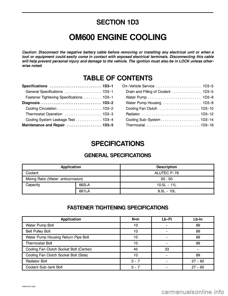
GENERAL SPECIFICATIONS
ApplicationDescription
CoolantALUTEC P-- 78
Mixing Ratio (Water: anticorrosion)50 : 50
Capacity662LA10.5L -- 11Lpy
661LA9.5L -- 10L
FASTENER TIGHTENING SPECIFICATIONS
ApplicationNSmLb-- FtLb-In
Water Pump Bolt10--89
Belt Pulley Bolt10--89
Water Pump Housing Return Pipe Bolt10--89
Thermostat Bolt10--89
Cooling Fan Clutch Socket Bolt (Center)4533--
Cooling Fan Clutch Socket Bolt (Side)10--89
Radiator Bolt3--7--27 -- 62
Coolant Sub-- tank Bolt3--7--27 -- 62