1997 SSANGYONG KORANDO section 2c
[x] Cancel search: section 2cPage 1083 of 2053
SSANGYONG MY2002
4F-100 ABS AND TCS
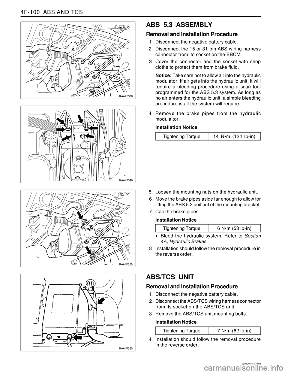
1
KAA4F330
KAA4F340
ABS 5.3 ASSEMBLY
Removal and Installation Procedure
1. Disconnect the negative battery cable.
2. Disconnect the 15 or 31-pin ABS wiring harness
connector from its socket on the EBCM.
3. Cover the connector and the socket with shop
cloths to protect them from brake fluid.
Notice: Take care not to allow air into the hydraulic
modulator. If air gets into the hydraulic unit, it will
require a bleeding procedure using a scan tool
programmed for the ABS 5.3 system. As long as
no air enters the hydraulic unit, a simple bleeding
procedure is all the system will require.
4. Remove the brake pipes from the hydraulic
modula tor.
Installation Notice
Tightening Torque 14 Nm (124 lb-in)
5. Loosen the mounting nuts on the hydraulic unit.
6. Move the brake pipes aside far enough to allow for
lifting the ABS 5.3 unit out of the mounting bracket.
7. Cap the brake pipes.
Installation Notice
ABS/TCS UNIT
Removal and Installation Procedure
1. Disconnect the negative battery cable.
2. Disconnect the ABS/TCS wiring harness connector
from its socket on the ABS/TCS unit.
3. Remove the ABS/TCS unit mounting bolts.
Installation Notice
KAA4F350
KAA4F360
Tightening Torque 6 Nm (53 lb-in)
Bleed the hydraulic system. Refer to Section
4A, Hydraulic Brakes.
8. Installation should follow the removal procedure in
the reverse order.
Tightening Torque 7 Nm (62 lb-in)
4. Installation should follow the removal procedure
in the reverse order.
Page 1085 of 2053
SSANGYONG MY2002
4F-102 ABS AND TCS
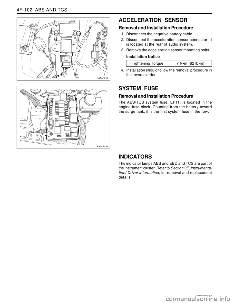
ACCELERATION SENSOR
Removal and Installation Procedure
1. Disconnect the negative battery cable.
2. Disconnect the acceleration sensor connector. It
is located at the rear of audio system.
3. Remove the acceleration sensor mounting bolts.
Installation Notice
SYSTEM FUSE
Removal and Installation Procedure
The ABS/TCS system fuse, EF11, is located in the
engine fuse block. Counting from the battery toward
the surge tank, it is the first system fuse in the row.
KAA4F410
KAA4F420
Tightening Torque 7 Nm (62 lb-in)
4. Installation should follow the removal procedure in
the reverse order.
INDICATORS
The indicator lamps ABS and EBD and TCS are part of
the instrument cluster. Refer to Section 9E, instrumenta-
tion/ Driver information, for removal and replacement
details.
Page 1086 of 2053
ABS AND TCS 4F-103
SSANGYONG MY2002
UNIT REPAIR
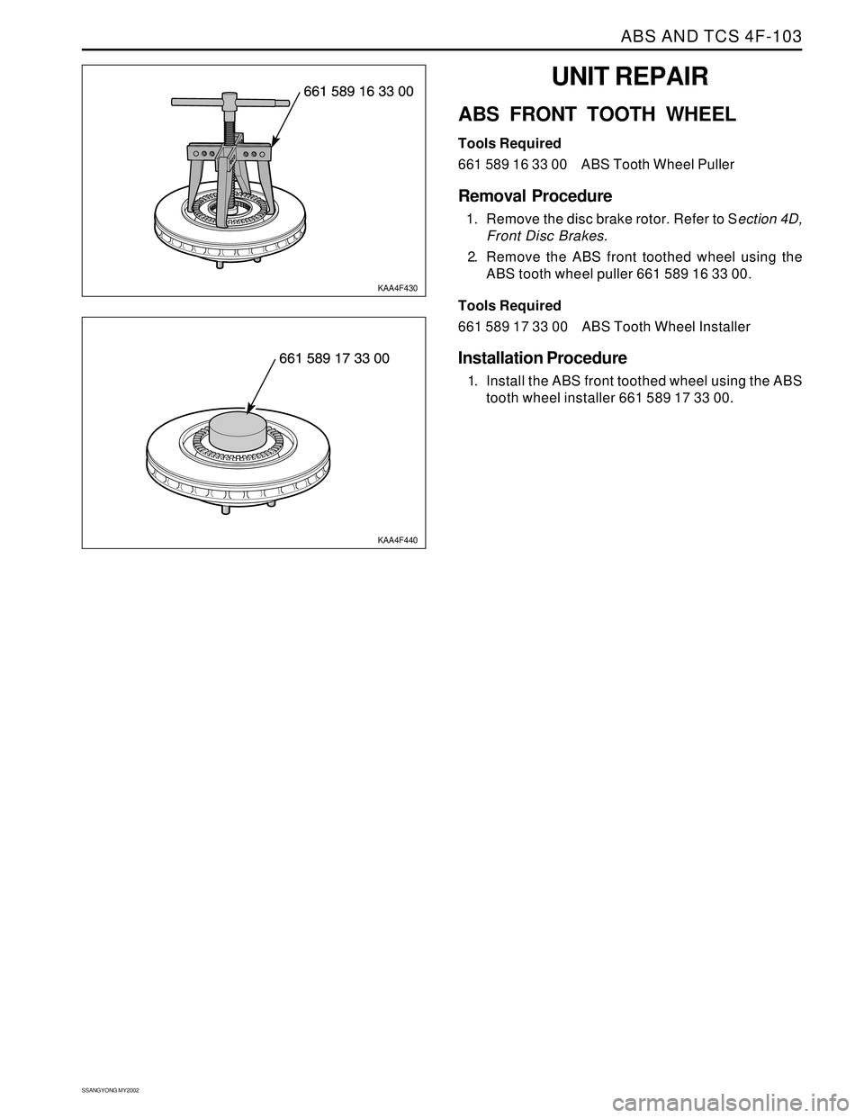
ABS FRONT TOOTH WHEEL
Tools Required
661 589 16 33 00 ABS Tooth Wheel Puller
Removal Procedure
1. Remove the disc brake rotor. Refer to Section 4D,
Front Disc Brakes.
2. Remove the ABS front toothed wheel using the
ABS tooth wheel puller 661 589 16 33 00.
Tools Required
661 589 17 33 00 ABS Tooth Wheel Installer
Installation Procedure
1. Install the ABS front toothed wheel using the ABS
tooth wheel installer 661 589 17 33 00.
KAA4F430
KAA4F440
Page 1088 of 2053
SECTION 4G
PARKING BRAKE
TABLE OF CONTENTS
Description and Operation..................................4G-2
Brake Caliper......................................................4G-2
Component Locator.............................................4G-3
Repair Instructions...............................................4G-4
On-Vehicle Service................................................4G-4Parking Brake Adjustment - Rear Disc Brakes.....4G-4
Parking Brake Lever............................................4G-5
Parking Brake Cable...........................................4G-6
Specifications......................................................4G-7
Fastener Tightening Specifications......................4G-7
Page 1091 of 2053
SSANGYONG MY2002
4G-4 PARKING BRAKE
KAA4G020
KAA4G030
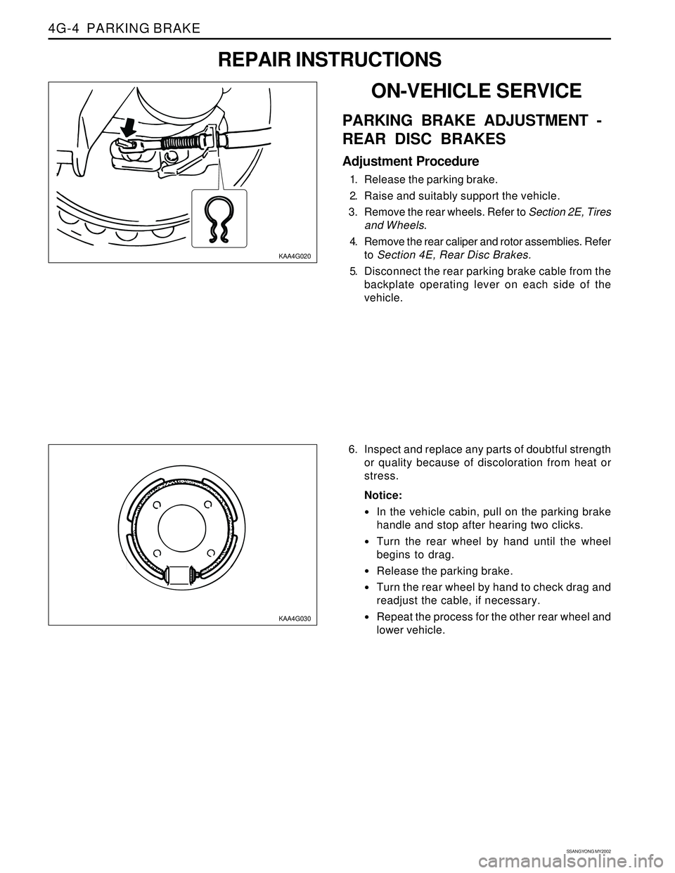
6. Inspect and replace any parts of doubtful strength
or quality because of discoloration from heat or
stress.
Notice:
In the vehicle cabin, pull on the parking brake
handle and stop after hearing two clicks.
Turn the rear wheel by hand until the wheel
begins to drag.
Release the parking brake.
Turn the rear wheel by hand to check drag and
readjust the cable, if necessary.
Repeat the process for the other rear wheel and
lower vehicle.
ON-VEHICLE SERVICE
PARKING BRAKE ADJUSTMENT -
REAR DISC BRAKES
Adjustment Procedure
1. Release the parking brake.
2. Raise and suitably support the vehicle.
3. Remove the rear wheels. Refer to Section 2E, Tires
and Wheels.
4. Remove the rear caliper and rotor assemblies. Refer
to Section 4E, Rear Disc Brakes.
5. Disconnect the rear parking brake cable from the
backplate operating lever on each side of the
vehicle.
REPAIR INSTRUCTIONS
Page 1092 of 2053
PARKING BRAKE 4G-5
SSANGYONG MY2002
KAA4G040
KAA4G050
KAA4G060
KAA4G070
PARKING BRAKE LEVER
Removal and Installation Procedure
1. Release the parking brake.
2. Raise and suitably support the vehicle.
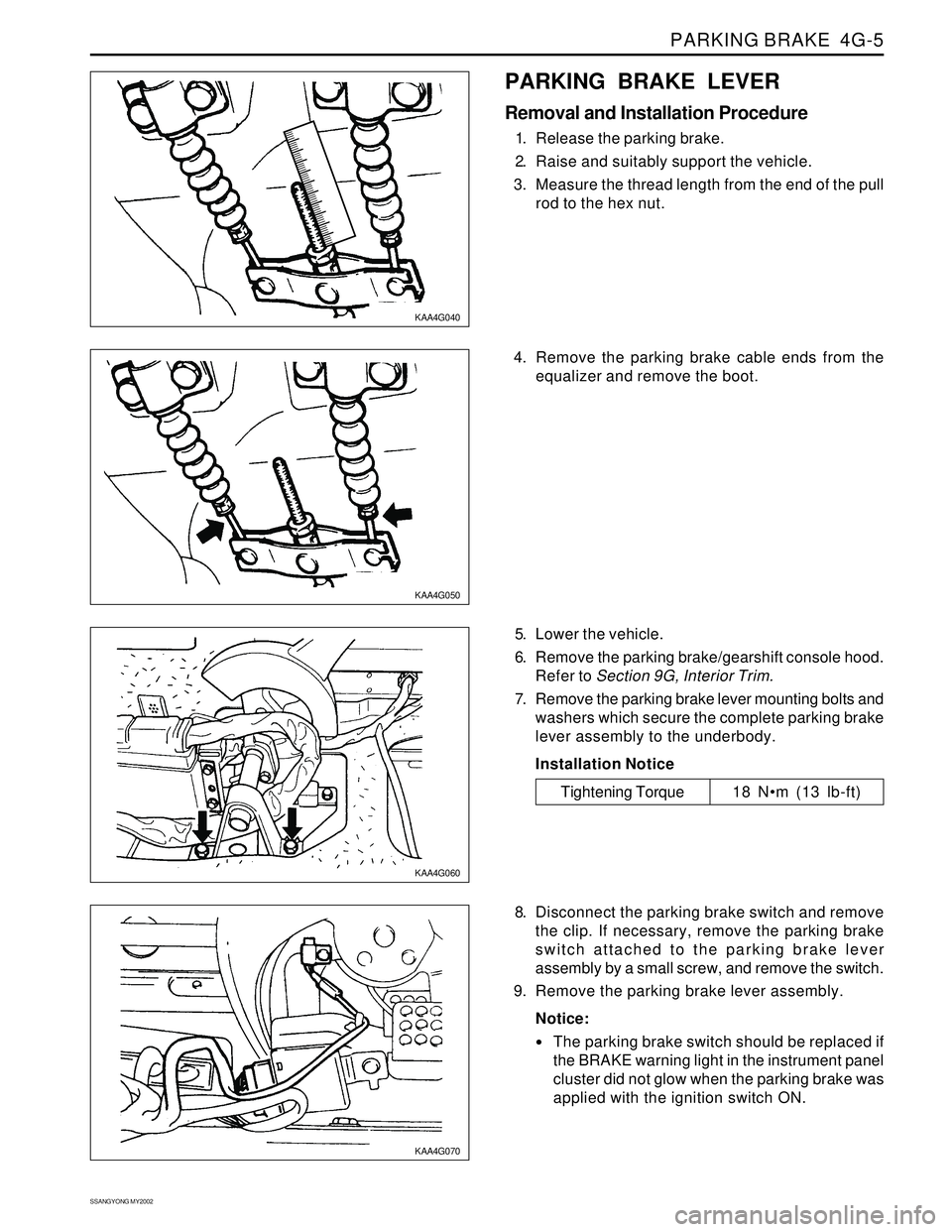
3. Measure the thread length from the end of the pull
rod to the hex nut.
5. Lower the vehicle.
6. Remove the parking brake/gearshift console hood.
Refer to Section 9G, Interior Trim.
7. Remove the parking brake lever mounting bolts and
washers which secure the complete parking brake
lever assembly to the underbody.
Installation Notice
8. Disconnect the parking brake switch and remove
the clip. If necessary, remove the parking brake
switch attached to the parking brake lever
assembly by a small screw, and remove the switch.
9. Remove the parking brake lever assembly.
Notice:
The parking brake switch should be replaced if
the BRAKE warning light in the instrument panel
cluster did not glow when the parking brake was
applied with the ignition switch ON.
Tightening Torque 18 Nm (13 lb-ft) 4. Remove the parking brake cable ends from the
equalizer and remove the boot.
Page 1095 of 2053
SECTION 5A
AUTOMATIC TRANSMISSION
CAUTION: Disconnect the negative battery cable before removing or installing any electrical unit or when a
tool or equipment could easily come in contact with exposed electrical terminals. Disconnecting this cable
will help prevent personal injury and damage to the vehicle. The ignition must also be in LOCK unless
otherwise noted.
TABLE OF CONTENTS
Description and Operation . . . . . . . . . . . . . . . . . 5A-2
BTRA M74 4WD Automatic Transmission . . . . . . 5A-2
Operators Interfaces . . . . . . . . . . . . . . . . . . . . . 5A-2
Control Systems . . . . . . . . . . . . . . . . . . . . . . . . 5A-3
Electronic Control System . . . . . . . . . . . . . . . . . 5A-3
Hydraulic Control System . . . . . . . . . . . . . . . . . . 5A-9
Hydraulic Control Circuit . . . . . . . . . . . . . . . . . . 5A-10
Power Train System . . . . . . . . . . . . . . . . . . . . . 5A-14
Power Flows . . . . . . . . . . . . . . . . . . . . . . . . . . 5A-18
Park and Neutral . . . . . . . . . . . . . . . . . . . . . . . 5A-20
Reverse . . . . . . . . . . . . . . . . . . . . . . . . . . . . . . 5A-22
Manual 1 . . . . . . . . . . . . . . . . . . . . . . . . . . . . . 5A-24
Drive 1 . . . . . . . . . . . . . . . . . . . . . . . . . . . . . . 5A-26
Drive 2 and Manual 2 . . . . . . . . . . . . . . . . . . . . 5A-28
Drive 3 and Manual 3 . . . . . . . . . . . . . . . . . . . . 5A-30
Drive 3 Lock Up and Manual 3 Lock Up . . . . . . 5A-32
Drive 4 (Overdrive) . . . . . . . . . . . . . . . . . . . . . 5A-34
Drive 4 Lock Up . . . . . . . . . . . . . . . . . . . . . . . . 5A-36
Diagnostic Information and Procedures . . . . . 5A-38
Diagnosis . . . . . . . . . . . . . . . . . . . . . . . . . . . . . 5A-38
Basic Knowledge Required . . . . . . . . . . . . . . . 5A-38
Functional Check Procedure . . . . . . . . . . . . . . . 5A-38
Transmission Fluid Level Service Procedure . . . 5A-38
Fluid Leak Diagnosis and Repair . . . . . . . . . . . 5A-39
Electrical / Garage Shift Test . . . . . . . . . . . . . . 5A-40
Road Test Procedure . . . . . . . . . . . . . . . . . . . . 5A-40
Electronic Adjustments . . . . . . . . . . . . . . . . . . 5A-40
Symptom Diagnosis . . . . . . . . . . . . . . . . . . . . . 5A-41
Drive Faults . . . . . . . . . . . . . . . . . . . . . . . . . . . 5A-41
Faulty Shift Pattern . . . . . . . . . . . . . . . . . . . . . . 5A-42Shift Quality Faults . . . . . . . . . . . . . . . . . . . . . . 5A-44
After Teardown Faults . . . . . . . . . . . . . . . . . . . 5A-46
Trouble Code Diagnosis - Gasoline Vehicle . . 5A-48
TCM Diagnostic System Overview . . . . . . . . . . 5A-48
Clearing Trouble Codes . . . . . . . . . . . . . . . . . . 5A-48
Diagnostic Trouble Codes . . . . . . . . . . . . . . . . 5A-48
Trouble Code Diagnosis - Diesel Vehicle . . . . . 5A-50
TCM Diagnostic System Overview . . . . . . . . . . 5A-50
Clearing Trouble Codes . . . . . . . . . . . . . . . . . . 5A-50
Diagnostic Trouble Codes . . . . . . . . . . . . . . . . 5A-50
Repair Instructions . . . . . . . . . . . . . . . . . . . . . . 5A-157
On-Vehicle Service . . . . . . . . . . . . . . . . . . . . . . . 5A-157
Transmission . . . . . . . . . . . . . . . . . . . . . . . . . . 5A-157
Unit Repair . . . . . . . . . . . . . . . . . . . . . . . . . . . . 5A-160
Rebuild Warnings . . . . . . . . . . . . . . . . . . . . . . 5A-160
Disassembly Procedure . . . . . . . . . . . . . . . . . . 5A-161
Assembly Procedure . . . . . . . . . . . . . . . . . . . . 5A-171
Front and Rear Band Adjustment . . . . . . . . . . . 5A-199
Gear Shift Control Lever . . . . . . . . . . . . . . . . . . 5A-202
Kickdown Switch . . . . . . . . . . . . . . . . . . . . . . . 5A-202
Specifications . . . . . . . . . . . . . . . . . . . . . . . . . . 5A-203
General Specification . . . . . . . . . . . . . . . . . . . . 5A-203
Fastener Tightening Specifications . . . . . . . . . . 5A-205
Schematic and Routing Diagrams . . . . . . . . . . 5A-206
TCM Wiring Diagrams (Gasoline Engine) . . . . . 5A-206
TCM Wiring Diagrams (Diesel Engine) . . . . . . . 5A-208
Connector End View . . . . . . . . . . . . . . . . . . . . . 5A-210
Special Tools and Equipment . . . . . . . . . . . . . 5A-211
Special Tools Table . . . . . . . . . . . . . . . . . . . . . 5A-211
Page 1098 of 2053

5A-4 AUTOMATIC TRANSMISSION
SSANGYONG MY2002
Output circuits which control external devices such
as the Variable Pressure Solenoid (VPS) driver, On/
Off solenoid drivers, a diagnostics output and the
driving mode indicator light.
Processing Logic
Shift schedule and calibration information is stored in
an Erasable Programmable Read Only Memory (EPROM).
Throttle input calibration constants and the diagnostics
information are stored in Electrically Erasable Program-
mable Read Only Memory (EEPROM) that retains the
memory even when power to the TCM is disconnected.
TCM continuously monitors the input values and uses
these, via the shift schedule, to determine the required
gear state. At the same time it monitors, via the solenoid
outputs, the current gear state, whenever the input
conditions change such that the required gear state is
different to the current gear state, the TCM initiates a
gear shift to bring the two states back into line.
Once the TCM has determined the type of gearshift
required the TCM accesses the shift logic, estimates
the engine torque output, adjusts the variable pressure
solenoid ramp pressure then executes the shift.The TCM continuously monitors every input and output
circuit for short or open circuits and operating range.
When a failure or abnormal operation is detected the
TCM records the condition code in the diagnostics
memory and implements a Limp Home Mode (LHM).
The actual limp home mode used depends upon the
failure detected with the object to maintain maximum
drive-ability without damaging the transmission. In
general input failures are handled by providing a default
value. Output failures, which are capable of damaging
the transmission, result in full limp mode giving only
third or fourth gear and reverse. For further details of
limp modes and memory retention refer to the
Diagnostic Trouble Code Diagnosis Section.
The TCM is designed to operate at ambient
temperatures between - 40 and 85 °C (- 40 and 185 °F).
It is also protected against electrical noise and voltage
spikes, however all the usual precautions should be
observed, for example when arc welding or jump
starting.
TCM Inputs
To function correctly, the TCM requires engine speed,
vehicle speed, transmission fluid temperature, throttle
position, gear position and Kickdown Switch inputs to
determine the variable pressure solenoid current ramp
and on/off solenoid states.
KAA5A030
This ensures the correct gear selection and shift feel
for all driving conditions.
The inputs required by the TCM are as follows;