Page 888 of 2053
SECTION 3C
PROPELLER SHAFT
TABLE OF CONTENTS
Components Locator............................................3C-2
Diagnostic Information and Procedures...............3C-3
Propeller Shaft.....................................................3C-3
Repair Instructions................................................3C-4
On-Vehicle Service.................................................3C-4
Front Propeller Shaft............................................3C-4Rear Propeller Shaft.............................................3C-4
Unit Repair............................................................3C-6
Propeller Shaft.....................................................3C-6
Specifications.......................................................3C-7
Fastener Tightening Specifications.......................3C-7
Page 893 of 2053
SSANGYONG MY2002
3C-6 PROPELLER SHAFT
UNIT REPAIR
PROPELLER SHAFT
Removal and Installation Procedure
1. Remove the front propeller shaft. Refer to “Front
Propeller Shaft” in this section.
2. Place alignment marks before removing the spider.
KAA3C100
KAA3C120
KAA3C110
KAA3C130
3. Using a snap ring pliers, remove the snap ring.
4. Slightly tapping the yoke shoulder using a brass
hammer, remove the bearing. Remove the
remaining bearings in the same way.
5. Disassemble the universal joint parts.
Installation Notice:
Clean the disassembled parts and replace them
if damaged.
Apply grease to the inner of the bearing cap of
the needle roller bearing and assemble the needle
roller.
GreaseEP#2
Page 895 of 2053

SECTION 3D
REAR AXLE
TABLE OF CONTENTS
General Description and Operation.................3D-2
Specifications...................................................3D-2
Fastener Tightening Specifications..................3D-2
Diagnostic Information and Procedures........3D-3
Component Locator .........................................3D-4
Rear Axle Assembly .........................................3D-4
Cross Sectional View........................................3D-5
Rear Axle Shaft Assembly...............................3D-6
Maintenance and Repair..................................3D-8
On-Vehicle Service ..............................................3D-8Axle Shaft Assembly (With Disc Brake)..........3D-8
Axle Shaft Assembly (With Drum Brake)...... 3D-11
Rear Axle Housing .......................................... 3D-13
Unit Repair....................................................... 3D-18
Axle Assembly............................................... 3D-18
Differential Gear Assembly............................ 3D-20
Drive Shaft...................................................... 3D-25
Special Tools and Equipment....................... 3D-26
Special Tools Table........................................ 3D-26
Page 899 of 2053
REAR AXLE 3D-5
SSANGYONG MY2002
CROSS SECTIONAL VIEW
KAA3D020
1 Rear Axle Shaft Assembly
2 Bracket Assembly
3 Hub Oil Seal
4 Bolt
5 Axle Shaft Tube6 Coil Spring Seat (Lower)
7 Caliper Assembly
8 Input Shaft/Flange
9 Rod Mounting Bracket
10 Wheel Speed Sensor
Page 919 of 2053

REAR AXLE 3D-25
SSANGYONG MY2002
KAA3D670
KAA3D660
DRIVE SHAFT
Tools Required
661 589 15 33 00 Rear Hub Bearing Installer
661589 18 33 00 Axle Bearing Puller Plate
661 589 18 33 01 Rear Axle Bearing Remover
661 589 18 33 02 Rear Axle Oil Seal Remover
Disassembly Procedure
1. Remove the rear drive shaft from the vehicle. Refer
to “Rear Drive Shaft” in this section.
2. Remove the toothed ring using the axle bearing
puller plate 661 589 18 33 00 and rear axle bearing
remover 661 589 18 33 01 by press.
3. Remove the rear drive shaft oil seal bearing using
the axle bearing puller plate 661 589 18 33 00 and
rear axle oil seal remover 661 589 18 33 02 by
press.
4. Remove the rear disc brake rotor shield.
3. Install the retainer drive shaft bearing using the
rear hub bearing installer 661 589 15 33 00 by press.
4. Install the rear drive shaft. Refer to “Rear Drive
Shaft” in this section.
KAA3D690
KAA3D680
Assembly Procedure
1. Install the rear disc brake rotor shield.
2. Install the rear drive shaft bearing oil seal using
the rear hub bearing installer 661 589 15 33 00 by
press.
Page 921 of 2053

SECTION 4A
HYDRAULIC BRAKES
CAUTION: Disconnect the negative battery cable before removing or installing any electrical unit or when
a tool or equipment could easily come in contact with exposed electrical terminals. Disconnecting this
cable will help prevent personal injury and damage to the vehicle. The ignition must also be in LOCK
unless otherwise noted.
TABLE OF CONTENTS
Description and Operation...................................4A-2
General Description.............................................4A-2
Diagnostic Information and Procedures..............4A-3
Brake System Testing ..........................................4A-3
Brake Hose Inspection.........................................4A-3
Brake Warning Lamp Circuit Description..............4A-4
Brake Warning Lamp Diagnosis...........................4A-5
LCRV (Load Conscious Reducing Valve)..............4A-8
Repair Instructions..............................................4A-10On-Vehicle Service...............................................4A-10
Manual Bleeding The Brakes.............................4A-10
Front Brake Hose...............................................4A-13
Rear Brake Hose...............................................4A-13
Stoplamp Switch................................................4A-14
Brake Pedal.......................................................4A-14
Specifications.....................................................4A-15
General Specification .........................................4A-15
Fastener Tightening Specifications.....................4A-16
Page 930 of 2053

SSAMGYONG MY2002
4A-10 HYDRAULIC BRAKES
KAA4A020
KAA4A030
Notice: Keep brake fluid away from painted surfaces
because brake fluid will damage the paint finish.
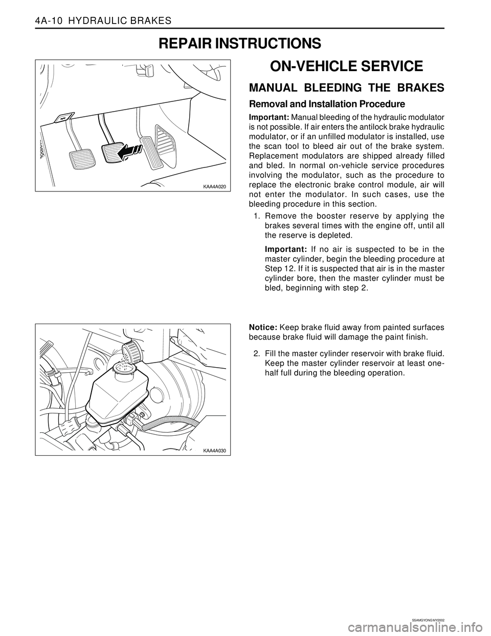
2. Fill the master cylinder reservoir with brake fluid.
Keep the master cylinder reservoir at least one-
half full during the bleeding operation.
ON-VEHICLE SERVICE
MANUAL BLEEDING THE BRAKES
Removal and Installation Procedure
Important: Manual bleeding of the hydraulic modulator
is not possible. If air enters the antilock brake hydraulic
modulator, or if an unfilled modulator is installed, use
the scan tool to bleed air out of the brake system.
Replacement modulators are shipped already filled
and bled. In normal on-vehicle service procedures
involving the modulator, such as the procedure to
replace the electronic brake control module, air will
not enter the modulator. In such cases, use the
bleeding procedure in this section.
1. Remove the booster reserve by applying the
brakes several times with the engine off, until all
the reserve is depleted.
Important: If no air is suspected to be in the
master cylinder, begin the bleeding procedure at
Step 12. If it is suspected that air is in the master
cylinder bore, then the master cylinder must be
bled, beginning with step 2.
REPAIR INSTRUCTIONS
Page 933 of 2053

HYDRAULIC BRAKES 4A-13
SSANGYONG MY2002
Tightening Torque 17 Nm (13 lb-ft)
FRONT BRAKE HOSE
Removal and Installation Procedure
1. Raise and suitably support the vehicle.
2. Disconnect the brake line from the brake hose sup
port bracket on the front frame on each side of the
vehicle and remove the retainer.
Installation Notice
KAA4A080
KAA4A090
KAA4A100
KAA4A110
3. Remove the brake hose from the brake hose
support bracket on the upper control arm.
4. Remove the front brake hose-to-front caliper
assembly bolt.
5. Remove the ring seals and the disc brake hose.
Installation Notice
Tightening Torque 30 Nm (22 lb-ft)
Bleed the brake system. Refer to “Manual
Bleeding the Brakes” in this section.
Check the brake system for leaks.
6. Installation should follow the removal procedure
in the reverse order.
REAR BRAKE HOSE
Removal and Installation Procedure
1. Raise and suitably support the vehicle.
2. Disconnect the brake line from the disc brake hose
at the rear axle bracket on each side of the vehicle.
Installation Notice
Tightening Torque 17 Nm (13 lb-ft)