1997 SSANGYONG KORANDO transfer case
[x] Cancel search: transfer casePage 1438 of 2053
TRANSFER CASE (PART TIME - 4408) 5D2-39
SSANGYONG MY2002
KAA5D860
KAA5D870
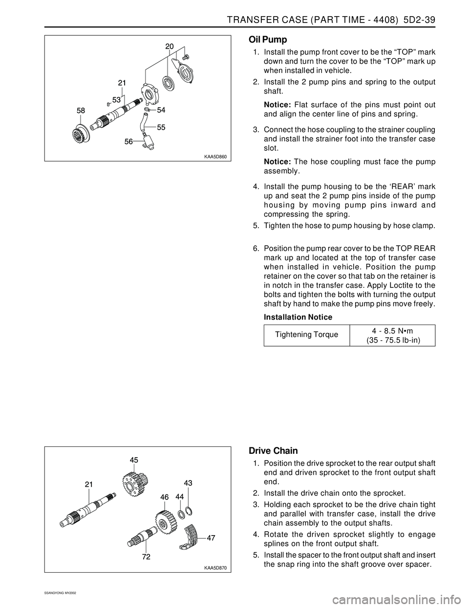
Oil Pump
1. Install the pump front cover to be the “TOP” mark
down and turn the cover to be the “TOP” mark up
when installed in vehicle.
2. Install the 2 pump pins and spring to the output
shaft.
Notice: Flat surface of the pins must point out
and align the center line of pins and spring.
3. Connect the hose coupling to the strainer coupling
and install the strainer foot into the transfer case
slot.
Notice: The hose coupling must face the pump
assembly.
4. Install the pump housing to be the ‘REAR’ mark
up and seat the 2 pump pins inside of the pump
housing by moving pump pins inward and
compressing the spring.
5. Tighten the hose to pump housing by hose clamp.
6. Position the pump rear cover to be the TOP REAR
mark up and located at the top of transfer case
when installed in vehicle. Position the pump
retainer on the cover so that tab on the retainer is
in notch in the transfer case. Apply Loctite to the
bolts and tighten the bolts with turning the output
shaft by hand to make the pump pins move freely.
Installation Notice
Tightening Torque4 - 8.5 Nm
(35 - 75.5 lb-in)
Drive Chain
1. Position the drive sprocket to the rear output shaft
end and driven sprocket to the front output shaft
end.
2. Install the drive chain onto the sprocket.
3. Holding each sprocket to be the drive chain tight
and parallel with transfer case, install the drive
chain assembly to the output shafts.
4. Rotate the driven sprocket slightly to engage
splines on the front output shaft.
5. Install the spacer to the front output shaft and insert
the snap ring into the shaft groove over spacer.
Page 1439 of 2053
SSANGYONG MY2002
5D2-40 TRANSFER CASE (PART TIME - 4408)
KAA5D880
KAA5D890
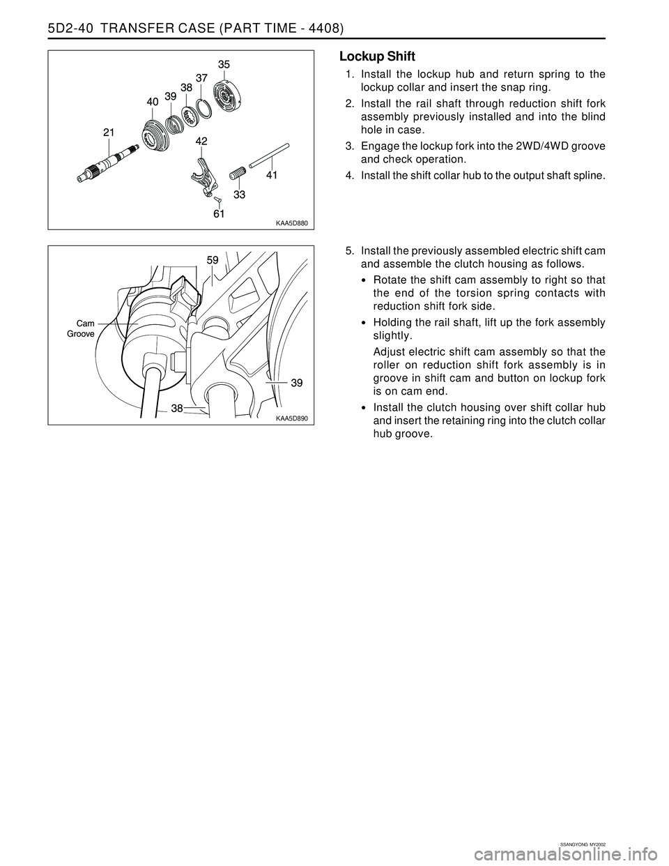
Lockup Shift
1. Install the lockup hub and return spring to the
lockup collar and insert the snap ring.
2. Install the rail shaft through reduction shift fork
assembly previously installed and into the blind
hole in case.
3. Engage the lockup fork into the 2WD/4WD groove
and check operation.
4. Install the shift collar hub to the output shaft spline.
5. Install the previously assembled electric shift cam
and assemble the clutch housing as follows.
Rotate the shift cam assembly to right so that
the end of the torsion spring contacts with
reduction shift fork side.
Holding the rail shaft, lift up the fork assembly
slightly.
Adjust electric shift cam assembly so that the
roller on reduction shift fork assembly is in
groove in shift cam and button on lockup fork
is on cam end.
Install the clutch housing over shift collar hub
and insert the retaining ring into the clutch collar
hub groove.
Page 1440 of 2053
TRANSFER CASE (PART TIME - 4408) 5D2-41
SSANGYONG MY2002
KAA5D900
Tightening Torque8 - 11 Nm
(71 - 97 lb-in)
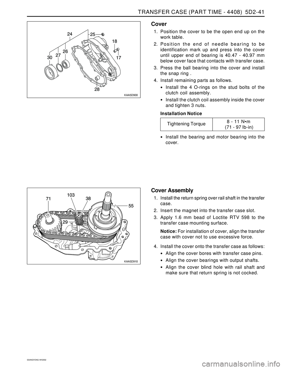
Cover
1. Position the cover to be the open end up on the
work table.
2. Position the end of needle bearing to be
identification mark up and press into the cover
until upper end of bearing is 40.47 - 40.97 mm
below cover face that contacts with transfer case.
3. Press the ball bearing into the cover and install
the snap ring .
4. Install remaining parts as follows.
Install the 4 O-rings on the stud bolts of the
clutch coil assembly.
Install the clutch coil assembly inside the cover
and tighten 3 nuts.
Installation Notice
Install the bearing and motor bearing into the
cover.
KAA5D910
Cover Assembly
1. Install the return spring over rail shaft in the transfer
case.
2. Insert the magnet into the transfer case slot.
3. Apply 1.6 mm bead of Loctite RTV 598 to the
transfer case mounting surface.
Notice: For installation of cover, align the transfer
case with cover not to use excessive force.
4. Install the cover onto the transfer case as follows:
Align the cover bores with transfer case pins.
Align the cover bearings with output shafts.
Align the cover blind hole with rail shaft and
make sure that return spring is not cocked.
Page 1441 of 2053
SSANGYONG MY2002
5D2-42 TRANSFER CASE (PART TIME - 4408)
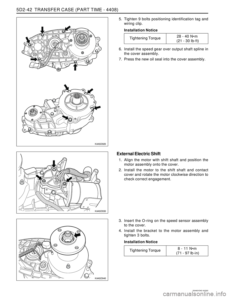
5. Tighten 9 bolts positioning identification tag and
wiring clip.
Installation Notice
6. Install the speed gear over output shaft spline in
the cover assembly.
7. Press the new oil seal into the cover assembly.
Tightening Torque28 - 40 Nm
(21 - 30 lb-ft)
KAA5D920
KAA5D930
KAA5D940
External Electric Shift
1. Align the motor with shift shaft and position the
motor assembly onto the cover.
2. Install the motor to the shift shaft and contact
cover and rotate the motor clockwise direction to
check correct engagement.
3. Insert the O-ring on the speed sensor assembly
to the cover.
4. Install the bracket to the motor assembly and
tighten 3 bolts.
Installation Notice
Tightening Torque8 - 11 Nm
(71 - 97 lb-in)
Page 1442 of 2053
TRANSFER CASE (PART TIME - 4408) 5D2-43
SSANGYONG MY2002
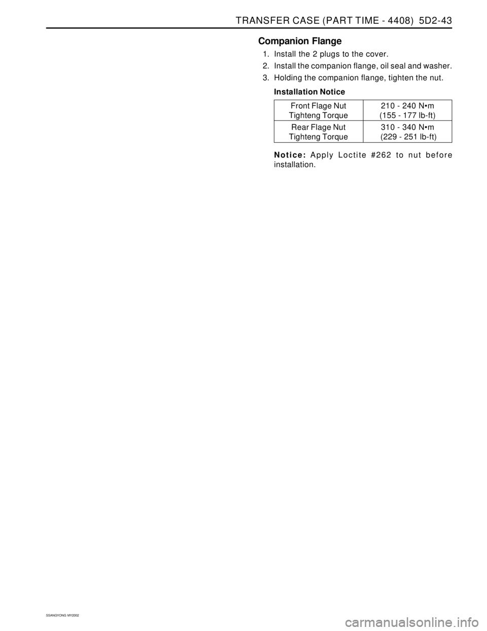
Companion Flange
1. Install the 2 plugs to the cover.
2. Install the companion flange, oil seal and washer.
3. Holding the companion flange, tighten the nut.
Installation Notice
Notice: Apply Loctite #262 to nut before
installation.210 - 240 Nm
(155 - 177 lb-ft)
310 - 340 Nm
(229 - 251 lb-ft)
Front Flage Nut
Tighteng Torque
Rear Flage Nut
Tighteng Torque
Page 1868 of 2053
2-4 2-4 2-4 2-4
2-4
ELECTRICAL WIRING DIAGRAMS ELECTRICAL WIRING DIAGRAMSELECTRICAL WIRING DIAGRAMS ELECTRICAL WIRING DIAGRAMS
ELECTRICAL WIRING DIAGRAMS
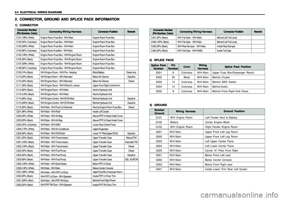
Engine Room Fuse Box - W/H Main
Engine Room Fuse Box - W/H Main
Engine Room Fuse Box - W/H Main
Engine Room FuseBox - W/H Main
Engine Room Fuse Box - W/H Engine Room
Engine Room Fuse Box - W/H Engine Room
Engine Room Fuse Box - W/H Engine Room
Engine Room Fuse Box - W/H Engine Room
W/H Engine Room - W/H Pre - Heating
W/H Engine Room - W/H Alternator
W/H Engine Room - W/H Alternator
W/H Engine Room - W/H Wheel G. sensor
W/H Engine Room - W/H Main
W/H Engine Room - W/H Main
W/H Engine Control - W/H ECM Main
W/H Engine Control - W/H ECM Main
W/H Main - W/H Fuel Cut Solenoid
W/H Main - W/H Roof
W/H Main - W/H Air Bag
W/H Main - W/H Air Bag
W/H Main - W/H SDM
W/H Main - W/H Air Conditioner
W/H Main - W/H ECM Main
W/H Main - W/H Transmission
W/H Main - W/H Transmission
W/H Main - W/H Transmission
W/H Main - W/H Fuel Pump
W/H Main - W/H Fuel Pump
W/H Main - W/H Fuel Pump
W/H Main - W/H Seat Heater
W/H Main - W/H Main
W/H Main - W/H FRT LH Door
W/H FRT LH Door - W/H Speaker
W/H Main - W/H FRT RH Door
W/H FRT RH Door - W/H Speaker
G201W/H Main Upper Front Left Leg Room
G202W/H Main Upper Front Left Leg Room
G203W/H Main Left Upper Center Facia
G204W/H Main Left Lower Center Facia
G205W/H Main Center "A" Pillar Front Right
G301W/H Main Below Front Left seat
G302W/H Main Below Center Console
G303W/H Main Below Front Right seat
G401W/H Main Inside Lower Trim Rear Left Quater
Engine Room Fuse Box
Engine Room Fuse Box
Engine Room Fuse Box
Engine Room Fuse Box
Engine Room Fuse Box
Engine Room Fuse Box
Engine Room Fuse Box
Engine Room Fuse Box
Bhind Battery
Below Air Cleaner
Below Air Cleaner
Upper Front Right Control Arm
Next to Hydraulic Unit
Next to Hydraulic Unit
Behind Hydraulic Unit
Behind Hydraulic Unit
Next to Engine Room Fuse Box
Inside Left Cluster
Above FRT LH Seat Under Cover
Above FRT LH Seat Under Cover
Lower Rear Center Facia
Upper Evaporator
Lower "A" Piller(Upper ECM)
Upper Transfer Case
Upper Transfer Case
Upper Transfer Case
Upper Transfer Case
Upper Transfer Case
Upper Transfer Case
Below FRT LH Seat
Below Center Console
Upper Fuse Box
(Passenger Room)
Inside FRT LH Door Trim
Behind Front Right Panel
Inside FRT RH Door Trim
2. 2.2. 2.
2.
CONNECT CONNECTCONNECT CONNECT
CONNECT
OR, OR,OR, OR,
OR,
GR GR GR GR
GR
OUND AND SPLICE PA OUND AND SPLICE PAOUND AND SPLICE PA OUND AND SPLICE PA
OUND AND SPLICE PA
CK INFORMA CK INFORMACK INFORMA CK INFORMA
CK INFORMA
TION TIONTION TION
TION1) 1)1) 1)
1)
CONNECTOR CONNECTORCONNECTOR CONNECTOR
CONNECTORConnector Number Connector NumberConnector Number Connector Number
Connector Number
(Pin Number, Color) (Pin Number, Color)(Pin Number, Color) (Pin Number, Color)
(Pin Number, Color)Connecting Connecting Connecting Connecting
Connecting
Wiring Harness Wiring HarnessWiring Harness Wiring Harness
Wiring Harness
Connector Position Connector PositionConnector Position Connector Position
Connector Position
C101 (19Pin, White)
C102 (4Pin, Colorless)
C103 (22Pin, White)
C104 (8Pin, Colorless)
C105 (10Pin, White)
C106 (3Pin, Black)
C107 (20Pin, White)
C108 (6Pin, Colorless)
C109 (1Pin, Black)
C110 (2Pin, Black)
C110 (4Pin, Black)
C111 (3Pin, Black)
C112 (6Pin, Black)
C113 (12Pin, Black)
C114 (6Pin, Gray)
C115 (40Pin, Black)
C116 (3Pin, Black)
C201 (8Pin, White)
C202 (4Pin, White)
C203 (2Pin, Black)
C204 (4Pin, Colorless)
C205 (17Pin, White)
C206 (6Pin, Black)
C301 (2Pin, Black)
C301 (16Pin, Black)
C302 (10Pin, Black)
C303 (3Pin, Black)
C303 (4Pin, Black)
C303 (6Pin, Black)
C304 (10Pin, White)
C305 (14Pin, White)
C351 (22Pin, White)
C352 (2Pin, Black)
C361 (22Pin, Blue)
C362 (2Pin, Black)
2) 2)2) 2)
2)
SPLICE PACK SPLICE PACKSPLICE PACK SPLICE PACK
SPLICE PACK
S201
S202
S203
S204
S205Splice Pack Position Splice Pack PositionSplice Pack Position Splice Pack Position
Splice Pack Position Wiring WiringWiring Wiring
Wiring
Harness HarnessHarness Harness
Harness Color ColorColor Color
Color Splice Pack Splice PackSplice Pack Splice Pack
Splice Pack
Number NumberNumber Number
Number
Colorless
Black
Colorless
Colorless
ColorlessW/H Main
W/H Main
W/H Main
W/H Main
W/H MainUpper Fuse Box(Passenger Room)
Behind Cluster
Behind 4WD Switch
Behind Audio
Behind Front Right Kick Panel
Remark RemarkRemark Remark
Remark
Diesel only
Gasoline
Diesel
Gasoline
Gasoline
Diesel
Gasoline
Manual T/M
Automatic T/M
Diesel
Diesel
Gasoline
GSL : EURO IIIBehind Left Tail Lamp
Behind Left Tail Lamp
Inside Rear Bumper
Inside Tail Gate
Connector Number Connector NumberConnector Number Connector Number
Connector Number
(Pin Number, Color) (Pin Number, Color)(Pin Number, Color) (Pin Number, Color)
(Pin Number, Color)Connecting Connecting Connecting Connecting
Connecting
Wiring Harness Wiring HarnessWiring Harness Wiring Harness
Wiring Harness
Connector Position Connector PositionConnector Position Connector Position
Connector Position
C401 (2Pin, Black)
C402 (12Pin, Black)
C403 (3Pin, Black)
C404 (2Pin, Black)W/H Tail Gate - W/H Main
W/H Tail Gate - W/H Main
W/H Rear Bumper - W/H Main
W/H Tail Gate - W/H HMSL
Remark RemarkRemark Remark
Remark
3) 3)3) 3)
3)
GROUND GROUNDGROUND GROUND
GROUND
G101
G102
G103Ground Position Ground PositionGround Position Ground Position
Ground Position
Wiring Harness Wiring HarnessWiring Harness Wiring Harness
Wiring Harness Number NumberNumber Number
Number
Ground GroundGround Ground
Ground
W/H Engine Room
Battery
W/H Engine RoomLeft Fender Next to Battery
Center Engine Block
Right Fender Engine Room
Pin PinPin Pin
Pin
Number NumberNumber Number
Number
8
20
14
14
8
Page 1900 of 2053
5-6 5-6 5-6 5-6
5-6
ELECTRICAL WIRING DIAGRAMS ELECTRICAL WIRING DIAGRAMSELECTRICAL WIRING DIAGRAMS ELECTRICAL WIRING DIAGRAMS
ELECTRICAL WIRING DIAGRAMS
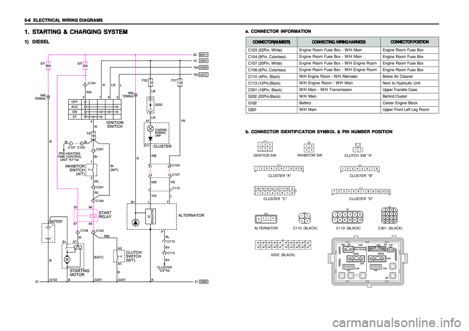
C103 (22Pin, White)
C104 (8Pin, Colorless)
C107 (20Pin, White)
C108 (6Pin, Colorless)
C110 (4Pin, Black)
C113 (12Pin,Black)
C301 (16Pin, Black)
S202 (20Pin,Black)
G102
G201
1. 1.1. 1.
1.
ST STST ST
ST
AR ARAR AR
AR
TING & CHARGING SYSTEM TING & CHARGING SYSTEMTING & CHARGING SYSTEM TING & CHARGING SYSTEM
TING & CHARGING SYSTEM1) 1)1) 1)
1)
DIESEL DIESELDIESEL DIESEL
DIESEL
b. b.b. b.
b.
CONNECTOR IDENTIFICATION SYMBOL & PIN NUMBER POSITION CONNECTOR IDENTIFICATION SYMBOL & PIN NUMBER POSITIONCONNECTOR IDENTIFICATION SYMBOL & PIN NUMBER POSITION CONNECTOR IDENTIFICATION SYMBOL & PIN NUMBER POSITION
CONNECTOR IDENTIFICATION SYMBOL & PIN NUMBER POSITION a. a.a. a.
a.
CONNECTOR INFORMATION CONNECTOR INFORMATIONCONNECTOR INFORMATION CONNECTOR INFORMATION
CONNECTOR INFORMATION
CLUTCH SW "A"
CLUSTER "B" IGNITION SW
INHIBITOR SWC110 (BLACK)
S202 (BLACK) CLUSTER "A"
CLUSTER "C" CLUSTER "D"
ALTERNATOR
C301 (BLACK)
C113 (BLACK)
CONNECTOR(NUMBER) CONNECTOR(NUMBER)CONNECTOR(NUMBER) CONNECTOR(NUMBER)
CONNECTOR(NUMBER)
CONNECTING. WIRING HARNESS CONNECTING. WIRING HARNESSCONNECTING. WIRING HARNESS CONNECTING. WIRING HARNESS
CONNECTING. WIRING HARNESS
Engine Room Fuse Box - W/H Main
Engine Room Fuse Box - W/H Main
Engine Room Fuse Box - W/H Engine Room
Engine Room Fuse Box - W/H Engine Room
W/H Engine Room - W/H Alternator
W/H Engine Room - W/H Main
W/H Main - W/H Transmission
W/H Main
Battery
W/H Main
CONNECTOR POSITION CONNECTOR POSITIONCONNECTOR POSITION CONNECTOR POSITION
CONNECTOR POSITION
Engine Room Fuse Box
Engine Room Fuse Box
Engine Room Fuse Box
Engine Room Fuse Box
Below Air Cleaner
Next to Hydraulic Unit
Upper Transfer Case
Behind Cluster
Center Engine Block
Upper Front Left Leg Room
Page 1902 of 2053
5-8 5-8 5-8 5-8
5-8
ELECTRICAL WIRING DIAGRAMS ELECTRICAL WIRING DIAGRAMSELECTRICAL WIRING DIAGRAMS ELECTRICAL WIRING DIAGRAMS
ELECTRICAL WIRING DIAGRAMS
a. a.a. a.
a.
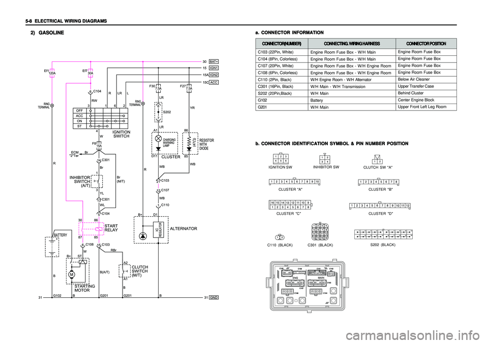
CONNECTOR INFORMATION CONNECTOR INFORMATIONCONNECTOR INFORMATION CONNECTOR INFORMATION
CONNECTOR INFORMATION
b. b.b. b.
b.
CONNECTOR IDENTIFICATION SYMBOL & PIN NUMBER POSITION CONNECTOR IDENTIFICATION SYMBOL & PIN NUMBER POSITIONCONNECTOR IDENTIFICATION SYMBOL & PIN NUMBER POSITION CONNECTOR IDENTIFICATION SYMBOL & PIN NUMBER POSITION
CONNECTOR IDENTIFICATION SYMBOL & PIN NUMBER POSITION
2) 2)2) 2)
2)
GASOLINE GASOLINEGASOLINE GASOLINE
GASOLINE
CLUTCH SW "A"
CLUSTER "B" IGNITION SWINHIBITOR SW
S202 (BLACK) CLUSTER "A"
CLUSTER "C" CLUSTER "D"
C301 (BLACK)
C110 (BLACK)
C103 (22Pin, White)
C104 (8Pin, Colorless)
C107 (20Pin, White)
C108 (6Pin, Colorless)
C110 (2Pin, Black)
C301 (16Pin, Black)
S202 (20Pin,Black)
G102
G201CONNECTOR(NUMBER) CONNECTOR(NUMBER)CONNECTOR(NUMBER) CONNECTOR(NUMBER)
CONNECTOR(NUMBER)
CONNECTING. WIRING HARNESS CONNECTING. WIRING HARNESSCONNECTING. WIRING HARNESS CONNECTING. WIRING HARNESS
CONNECTING. WIRING HARNESS
Engine Room Fuse Box - W/H Main
Engine Room Fuse Box - W/H Main
Engine Room Fuse Box - W/H Engine Room
Engine Room Fuse Box - W/H Engine Room
W/H Engine Room - W/H Alternator
W/H Main - W/H Transmission
W/H Main
Battery
W/H Main
CONNECTOR POSITION CONNECTOR POSITIONCONNECTOR POSITION CONNECTOR POSITION
CONNECTOR POSITION
Engine Room Fuse Box
Engine Room Fuse Box
Engine Room Fuse Box
Engine Room Fuse Box
Below Air Cleaner
Upper Transfer Case
Behind Cluster
Center Engine Block
Upper Front Left Leg Room