Page 1422 of 2053
TRANSFER CASE (PART TIME - 4408) 5D2-23
SSANGYONG MY2002
KAA5D300
KAA5D310
KAA5D320
7. Support the transfer case with jack and remove
the front and rear propeller shafts from the transfer
case.
Installation Notice
81 - 89 Nm
(60 - 66 lb-ft)
70 - 90 Nm
(52 - 66 lb-ft)
Tightening
TorqueFront
Rear
12 - 23 Nm
(9 - 17 lb-ft)
6 - 8 Nm
(53 - 71 lb-in)Tightening Torque(1)
Tightening Torque(2)
Tightening Torque35 - 60 Nm
(26 - 44 lb-ft) 8. Remove the center mounting nuts and end sides
mounting bolts of the cross member and then
remove the cross member.
Installation Notice
9. Remove the transfer case by removing the bolts
attaching the transfer case to the transmission.
Installation Notice
Notice: Apply long-term grease to the inner spline
of the transfer case input shaft.
10. Installation should follow the removal procedure
in the reverse order.
Page 1423 of 2053
TRANSFER CASE (PART TIME - 4408) 5D2-25
SSANGYONG MY2002
KAA5D380
KAA5D390
UNIT REPAIR
DISASSEMBLY PROCEDURE
Shift Motor Assembly
1. Separate the harness bracket.
2. Remove the shift motor mounting bolt and remove
the shift motor assembly.
KAA5D400
KAA5D410
Companion Flange
1. Holding the companion flange, remove the nut and
washer and then remove the companion flange.
2. Remove the oil seal.
3. Remove the companion flange from the case
cover.
Case Cover Assembly
1. Remove the cover mounting bolts(9), and the case
mounting bolts(5).
Notice: Identification tag has information required
for ordering replacement parts, so be careful not
to lose it.
2. Using a driver, pry and disconnect the sealant
bond of the cover and required case.
Page 1424 of 2053
SSANGYONG MY2002
5D2-26 TRANSFER CASE (PART TIME - 4408)
KAA5D420
KAA5D430
3. Remove the clutch coil wiring from the connector.
4. Remove the clutch coil assembly mounting nut.
KAA5D440
KAA5D450
5. Remove the snap ring and pull out the ball bearing
from the cover to remove the speed gear.
6. Remove the clutch coil assembly and the oil seal
from the cover.
7. Remove the speed sensor and the O-ring from
the case cover.
Page 1425 of 2053
TRANSFER CASE (PART TIME - 4408) 5D2-27
SSANGYONG MY2002
KAA5D460
KAA5D470
Transfer Case Assembly
1. Separate the shift motor shaft cam assembly and
the spring (1).
KAA5D480
KAA5D490
2. Remove the clutch housing assembly from the
output shaft.
Clutch Housing Component
(1) Retaining Ring
(2) Shift collar Hub
(3) Clutch Housing
Remove the shift cam from the shaft.
Fix the shaft at the vise with the cam removed
and remove the torsion bar using a driver.
3. Remove the 2WD/4WD lock up assembly, the lock
up fork and rail shaft from the output shaft.
Page 1426 of 2053
SSANGYONG MY2002
5D2-28 TRANSFER CASE (PART TIME - 4408)
KAA5D500
KAA5D510
KAA5D520
KAA5D530
2WD/4WD Lock Up Assembly Component.
(37) Snap Ring
(38) Lock up Hub
(39) Return Spring
(40) Lock up Collar
4. Remove the snap ring from the front output driven
sprocket and separate the snap ring and the
spacer.
5. Remove the driving sprocket, the driven sprocket
and the driving chain from the front/rear output
shaft.
6. Remove the oil pump assembly and the magnetic
from the output shaft.
Page 1427 of 2053
TRANSFER CASE (PART TIME - 4408) 5D2-29
SSANGYONG MY2002
KAA5D540
KAA5D550
Remove the bolt and the retainer. Separate the
output shaft and rear pump cover.
Remove the hose clamp and remove the hose
coupling cover from the pump housing.
Remove the hose clamp, the hose coupling and
the strainer.
Remove two pump pins and the spring from
the output shaft.
Separate the front pump and remove the output
shaft.
KAA5D560
Reduction Shift Parts
1. Remove the reduction hub and reduction shift fork
assembly from the case.
2. Remove the 2 shill fork facings from the shift fork
assembly.
3. To remove the roller cam and pin, cut elf the plastic
retainer when disassembling the fork assembly.
Front Output Assembly
1. Holding the companion flange, remove the nut and
washer and then remove the companion flange and
oil seal.
2. Remove the output shaft.
Page 1428 of 2053

SSANGYONG MY2002
5D2-30 TRANSFER CASE (PART TIME - 4408)
KAA5D570
KAA5D580
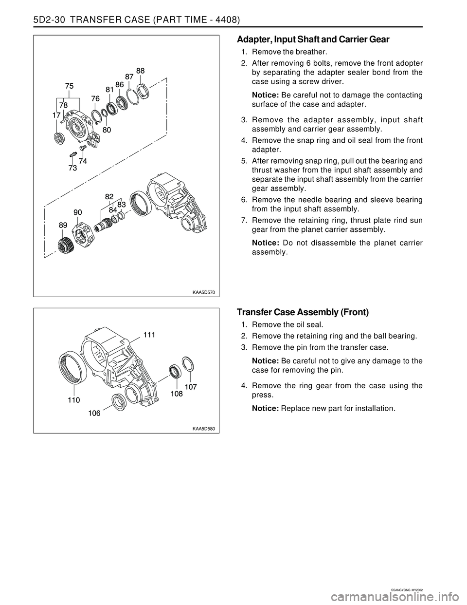
Adapter, Input Shaft and Carrier Gear
1. Remove the breather.
2. After removing 6 bolts, remove the front adopter
by separating the adapter sealer bond from the
case using a screw driver.
Notice: Be careful not to damage the contacting
surface of the case and adapter.
3. Remove the adapter assembly, input shaft
assembly and carrier gear assembly.
4. Remove the snap ring and oil seal from the front
adapter.
5. After removing snap ring, pull out the bearing and
thrust washer from the input shaft assembly and
separate the input shaft assembly from the carrier
gear assembly.
6. Remove the needle bearing and sleeve bearing
from the input shaft assembly.
7. Remove the retaining ring, thrust plate rind sun
gear from the planet carrier assembly.
Notice: Do not disassemble the planet carrier
assembly.
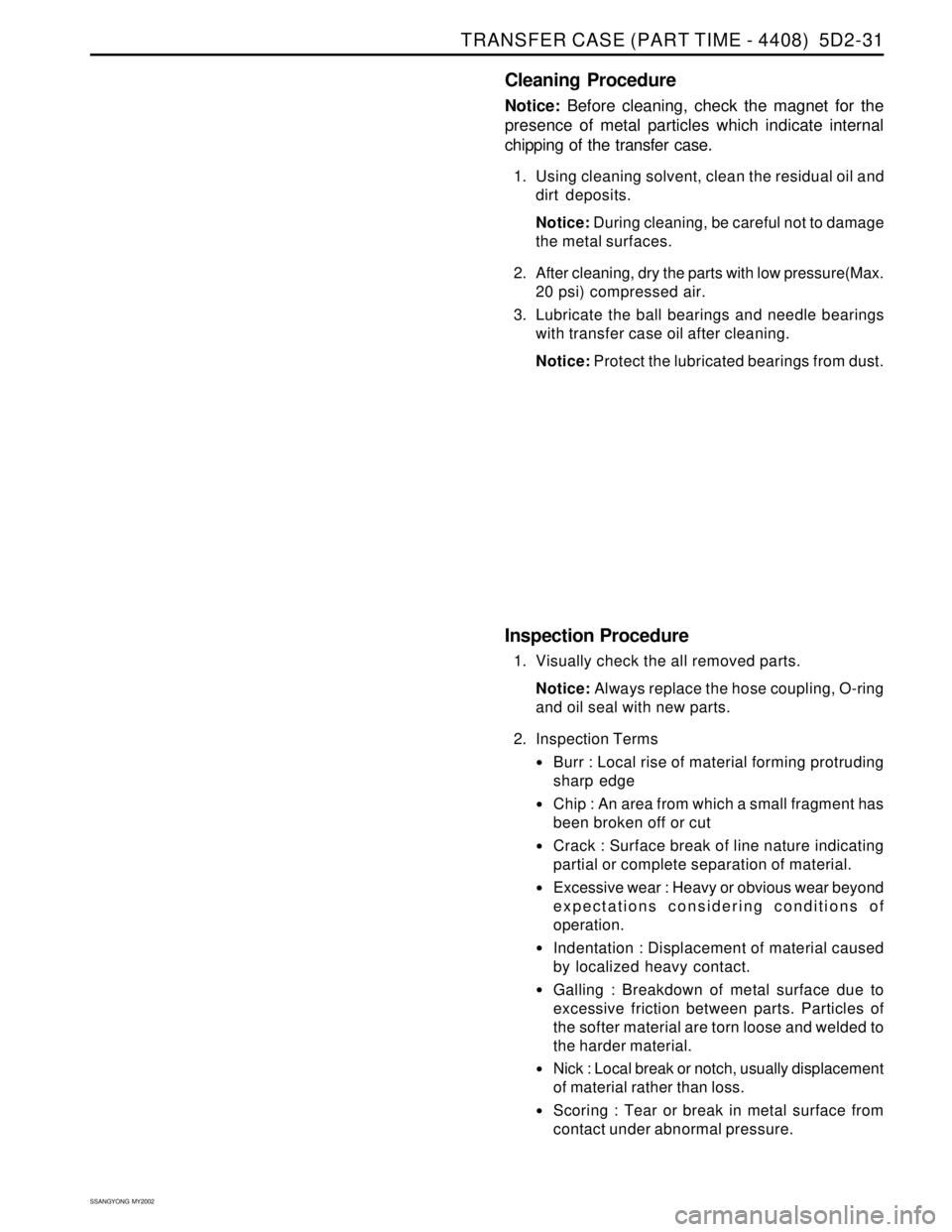
Transfer Case Assembly (Front)
1. Remove the oil seal.
2. Remove the retaining ring and the ball bearing.
3. Remove the pin from the transfer case.
Notice: Be careful not to give any damage to the
case for removing the pin.
4. Remove the ring gear from the case using the
press.
Notice: Replace new part for installation.
Page 1429 of 2053

TRANSFER CASE (PART TIME - 4408) 5D2-31
SSANGYONG MY2002
Cleaning Procedure
Notice: Before cleaning, check the magnet for the
presence of metal particles which indicate internal
chipping of the transfer case.
1. Using cleaning solvent, clean the residual oil and
dirt deposits.
Notice: During cleaning, be careful not to damage
the metal surfaces.
2. After cleaning, dry the parts with low pressure(Max.
20 psi) compressed air.
3. Lubricate the ball bearings and needle bearings
with transfer case oil after cleaning.
Notice: Protect the lubricated bearings from dust.
Inspection Procedure
1. Visually check the all removed parts.
Notice: Always replace the hose coupling, O-ring
and oil seal with new parts.
2. Inspection Terms
Burr : Local rise of material forming protruding
sharp edge
Chip : An area from which a small fragment has
been broken off or cut
Crack : Surface break of line nature indicating
partial or complete separation of material.
Excessive wear : Heavy or obvious wear beyond
expectations considering conditions of
operation.
Indentation : Displacement of material caused
by localized heavy contact.
Galling : Breakdown of metal surface due to
excessive friction between parts. Particles of
the softer material are torn loose and welded to
the harder material.
Nick : Local break or notch, usually displacement
of material rather than loss.
Scoring : Tear or break in metal surface from
contact under abnormal pressure.