1997 MERCEDES-BENZ ML430 ignition
[x] Cancel search: ignitionPage 3391 of 4133
MODEL 163 up to 31.8.01 with CODE (580) Air conditioning or Tempmatic for USA
MODEL 163 as of 1.9.01 with CODE (580a) Automatic air conditioning
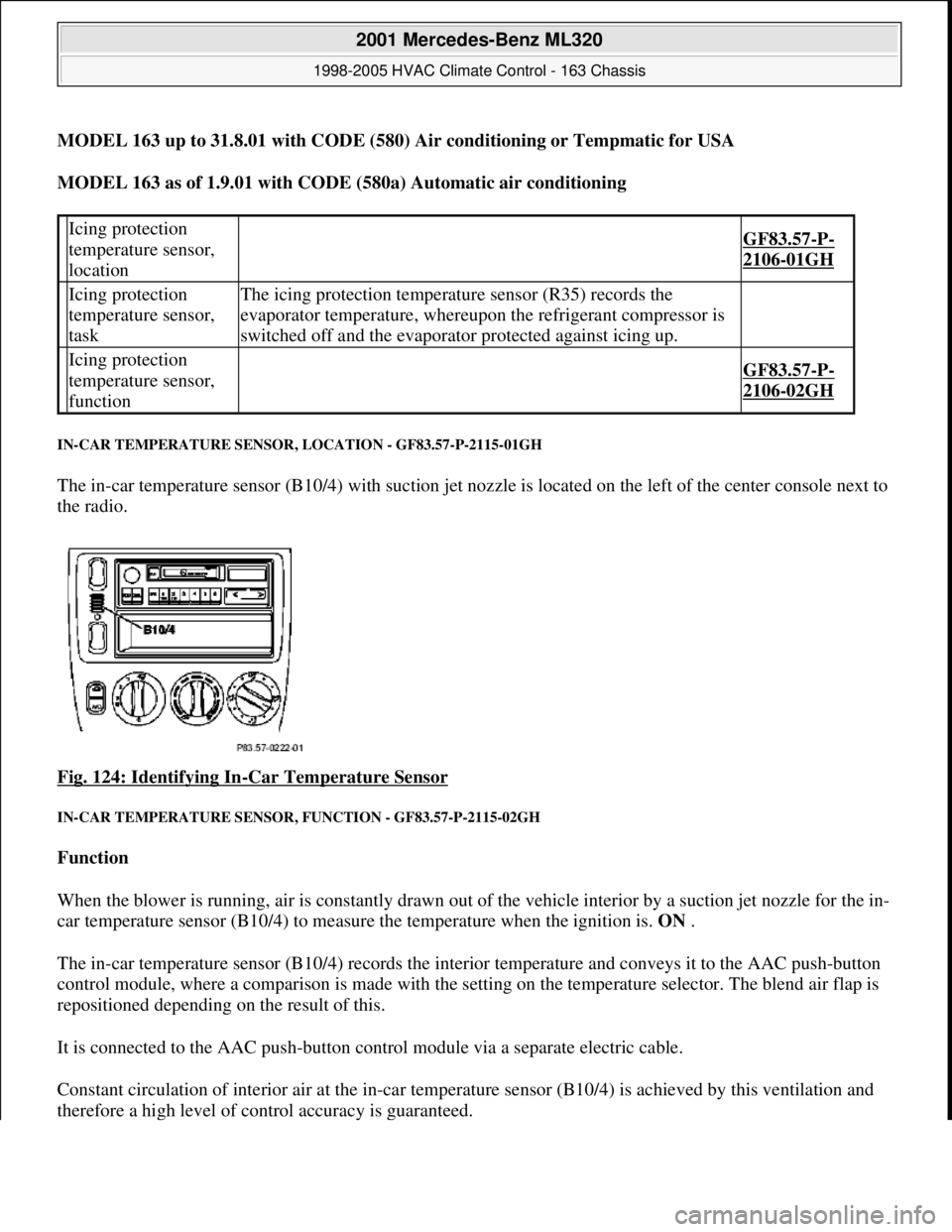
IN-CAR TEMPERATURE SENSOR, LOCATION - GF83.57-P-2115-01GH
The in-car temperature sensor (B10/4) with suction jet nozzle is located on the left of the center console next to
the radio.
Fig. 124: Identifying In
-Car Temperature Sensor
IN-CAR TEMPERATURE SENSOR, FUNCTION - GF83.57-P-2115-02GH
Function
When the blower is running, air is constantly drawn out of the vehicle interior by a suction jet nozzle for the in-
car temperature sensor (B10/4) to measure the temperature when the ignition is. ON .
The in-car temperature sensor (B10/4) records the interior temperature and conveys it to the AAC push-button
control module, where a comparison is made with the setting on the temperature selector. The blend air flap is
repositioned depending on the result of this.
It is connected to the AAC push-button control module via a separate electric cable.
Constant circulation of interior air at the in-car temperature sensor (B10/4) is achieved by this ventilation and
therefore a hi
gh level of control accuracy is guaranteed.
Icing protection
temperature sensor,
location
GF83.57-P-
2106-01GH
Icing protection
temperature sensor,
taskThe icing protection temperature sensor (R35) records the
evaporator temperature, whereupon the refrigerant compressor is
switched off and the evaporator protected against icing up.
Icing protection
temperature sensor,
function
GF83.57-P-
2106-02GH
2001 Mercedes-Benz ML320
1998-2005 HVAC Climate Control - 163 Chassis
me
Saturday, October 02, 2010 3:23:17 PMPage 147 © 2006 Mitchell Repair Information Company, LLC.
Page 3396 of 4133
When switching the ignition on or off and at speeds of less than 20 km/h the last measured temperature value is
used.
At ignition OFF, the last ambient temperature used for the control operation is stored.
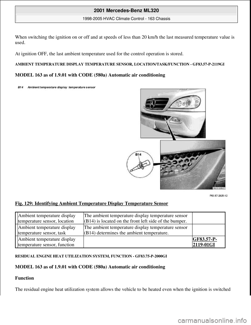
AMBIENT TEMPERATURE DISPLAY TEMPERATURE SENSOR, LOCATION/TASK/FUNCTION - GF83.57-P-2119GI
MODEL 163 as of 1.9.01 with CODE (580a) Automatic air conditioning
Fig. 129: Identifying Ambient Temperature Display Temperature Sensor
RESIDUAL ENGINE HEAT UTILIZATION SYSTEM, FUNCTION - GF83.75-P-2000GI
MODEL 163 as of 1.9.01 with CODE (580a) Automatic air conditioning
Function
The residual en
gine heat utilization system allows the vehicle to be heated even when the ignition is switched
Ambient temperature display
temperature sensor, locationThe ambient temperature display temperature sensor
(B14) is located on the front left side of the bumper.
Ambient temperature display
temperature sensor, taskThe ambient temperature display temperature sensor
(B14) determines the ambient temperature.
Ambient temperature display
temperature sensor, function GF83.57-P-
2119-01GI
2001 Mercedes-Benz ML320
1998-2005 HVAC Climate Control - 163 Chassis
me
Saturday, October 02, 2010 3:23:17 PMPage 152 © 2006 Mitchell Repair Information Company, LLC.
Page 3397 of 4133
OFF . To this end the system uses the residual heat of the engine. The residual engine heat is dissipated to the
coolant and routed through the heat exchanger with the aid of the heating water circulation pump. The air drawn
in by the blower motor is routed around the heat exchanger, whereby it is then warmed up. The heated air is
then routed over the air outlets into the passenger compartment.
The residual engine heat utilization system can only be used when the ignition is switched OFF.
Once the Rest push-button ( ) on the AAC push-button control module (N22) has been pressed the
following program sequence is run:
Blending air flaps are automatically controlled
Heating water circulation pump ON
The blower's control voltage is limited to a maximum value of 5 Volt.
End of program
Pressing the Rest push-button ( )
Timeout of 30 minutes period (repeated operation possible)
Protection against undervoltage at a battery voltage of less than 11 V (LED flashes)
Ignition ON
During the residual engine heat utilization function no function keys are accepted apart from the Rest push-
button ( ) and the set point adjusters.
SAFETY PRECAUTIONS
RISK OF EXPLOSION CAUSED BY WELDING OR SOLDERING WORK ON CLOSED AIR CONDITIONING SYSTEM.
RISK OF POISONING CAUSED BY INHALING OVERHEATED REFRIGERANT VAPORS. RISK OF INJURY TO SKIN AND
EYES CAUSED BY CONTACT WITH LIQUID REFRIGERANT. - AS83.00-Z-0001-01A
Never perform welding work on or near a closed air conditioning system. No smoking or open flames.
Wear safety glasses and protective gloves. Work only in well ventilated areas. Carry out repair work on
the air conditioning system circuit only after the system has been discharged.
Potential risks
Risk of explosion
When closed air conditionin
g systems (charged or empty) become heated, high pressures are produced that can
Rest push-button, location/task/function GF83.40-P-2148GI
Heating water circulation pump, location/task/ function GF83.20-P-2109GI
Heating system heat exchanger, location/ purpose/function GF83.20-P-2108GC
Blower motor, location/task/design/function GF83.10-P-2170GI
Blending air flap actuator, location/task/function GF83.57-P-2112GI
2001 Mercedes-Benz ML320
1998-2005 HVAC Climate Control - 163 Chassis
me
Saturday, October 02, 2010 3:23:17 PMPage 153 © 2006 Mitchell Repair Information Company, LLC.
Page 3407 of 4133
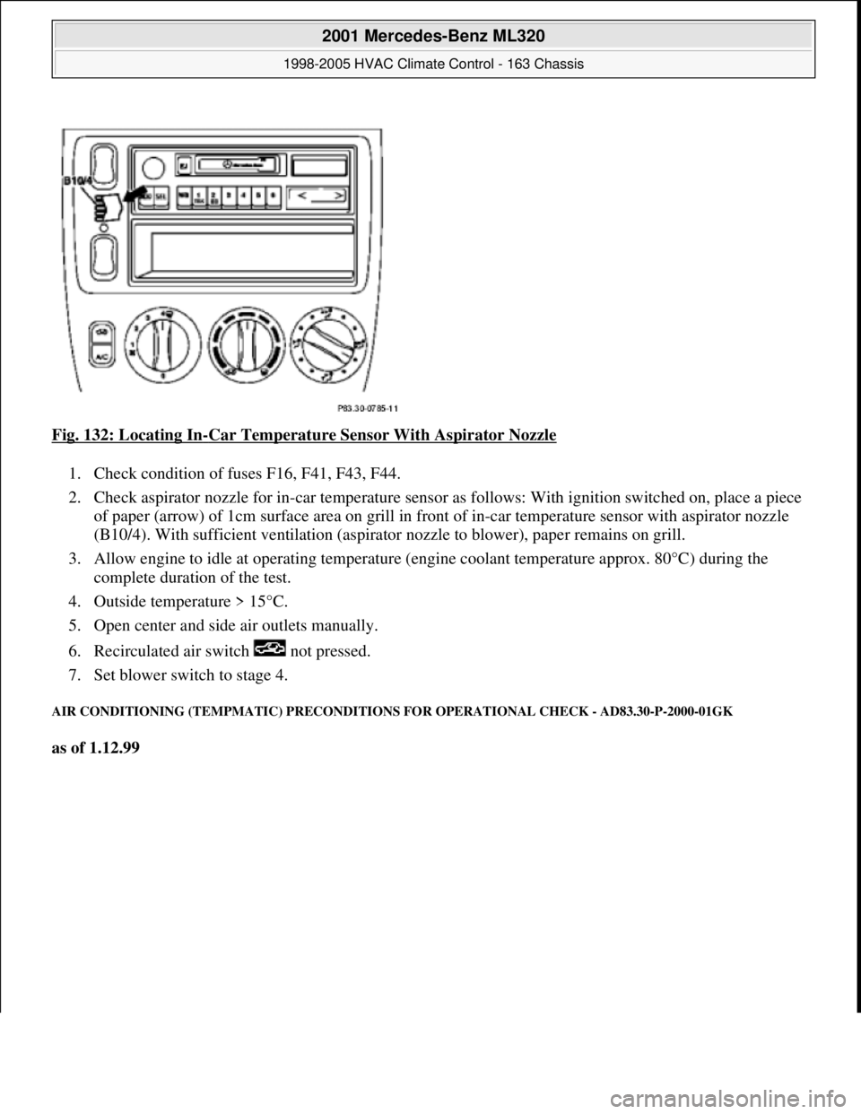
Fig. 132: Locating In-Car Temperature Sensor With Aspirator Nozzle
1. Check condition of fuses F16, F41, F43, F44.
2. Check aspirator nozzle for in-car temperature sensor as follows: With ignition switched on, place a piece
of paper (arrow) of 1cm surface area on grill in front of in-car temperature sensor with aspirator nozzle
(B10/4). With sufficient ventil ation (aspirator nozzle to blow er), paper remains on grill.
3. Allow engine to idle at operating temperature (engine coolant temperature approx. 80°C) during the
complete duration of the test.
4. Outside temperature > 15°C.
5. Open center and side air outlets manually.
6. Recirculated air switch not pressed.
7. Set blower switch to stage 4.
AIR CONDITIONING (TEMPMATIC ) PRECONDITIONS FOR OPERATIONAL CHECK - AD83.30-P-2000-01GK
as of 1.12.99
2001 Mercedes-Benz ML320
1998-2005 HVAC Climate Control - 163 Chassis
me
Saturday, October 02, 2010 3:23:17 PMPage 163 © 2006 Mitchell Repair Information Company, LLC.
Page 3408 of 4133
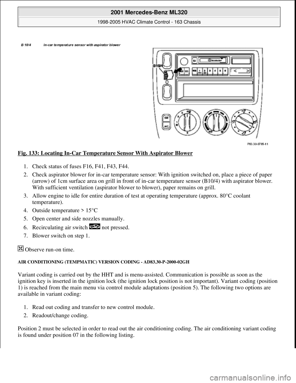
Fig. 133: Locating In-Car Temperature Sensor With Aspirator Blower
1. Check status of fuses F16, F41, F43, F44.
2. Check aspirator blower for in-car temperature sensor: With ignition switched on, place a piece of paper
(arrow) of 1cm surface area on grill in front of in-car temperature sensor (B10/4) with aspirator blower.
With sufficient ventilation (a spirator blower to blower), paper remains on grill.
3. Allow engine to idle for entire duration of test at operating temperature (approx. 80°C coolant
temperature).
4. Outside temperature > 15°C
5. Open center and side nozzles manually.
6. Recirculating air sw itch not pressed.
7. Blower switch on step 1.
Observe run-on time.
AIR CONDITIONING (T EMPMATIC) VERSION CO DING - AD83.30-P-2000-02GH
Variant coding is carried out by the HHT and is menu -assisted. Communication is possible as soon as the
ignition key is inserted in the ignition lock (the igniti on lock position is not important). Variant coding (position
1) is reached from the main menu via control module adaptations (position 5). The following two options are
available in variant coding:
1. Read out coding and transfer to new control module.
2. Readout/change coding.
Position 2 must be selected in order to read out th e air conditioning coding. The air conditioning variant coding
is found under position 07 in the following listing.
2001 Mercedes-Benz ML320
1998-2005 HVAC Climate Control - 163 Chassis
me
Saturday, October 02, 2010 3:23:17 PMPage 164 © 2006 Mitchell Repair Information Company, LLC.
Page 3413 of 4133
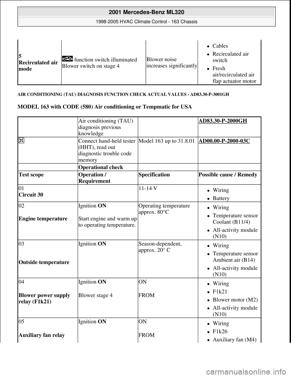
AIR CONDITIONING (TAU) DIAGNOSIS FUNCTION CHECK ACTUAL VALUES - AD83.30-P-3001GH
MODEL 163 with CODE (580) Air conditioning or Tempmatic for USA
5
Recirculated air
mode function switch illuminated
Blower switch on stage 4Blower noise
increases significantly
Cables
Recirculated air
switch
Fresh
air/recirculated air
flap actuator motor
Air conditioning (TAU)
diagnosis previous
knowledge AD83.30-P-2000GH
Connect hand-held tester
(HHT), read out
diagnostic trouble code
memoryModel 163 up to 31.8.01AD00.00-P-2000-03C
Operational check
Test scope Operation /
Requirement Specification Possible cause / Remedy
01
Circuit 30 11-14 VWiring
Battery
02Ignition ON Operating temperature
approx. 80°CWiring
Temperature sensor
Coolant (B11/4)
All-activity module
(N10)
Engine temperature Start engine and warm up
to operating temperature.
03Ignition ON Season-dependent,
approx. 20° CWiring
Temperature sensor
Ambient air (B14)
All-activity module
(N10)
Outside temperature
04Ignition ON ONWiring
F1k21
Blower motor (M2)
All-activity module
(N10)
Blower power supply
relay (F1k21) Blower stage 4FROM
05Ignition ON ONWiring
F1k26
Auxiliary fan (M4) Auxiliary fan relay FROM
2001 Mercedes-Benz ML320
1998-2005 HVAC Climate Control - 163 Chassis
me
Saturday, October 02, 2010 3:23:17 PMPage 169 © 2006 Mitchell Repair Information Company, LLC.
Page 3414 of 4133
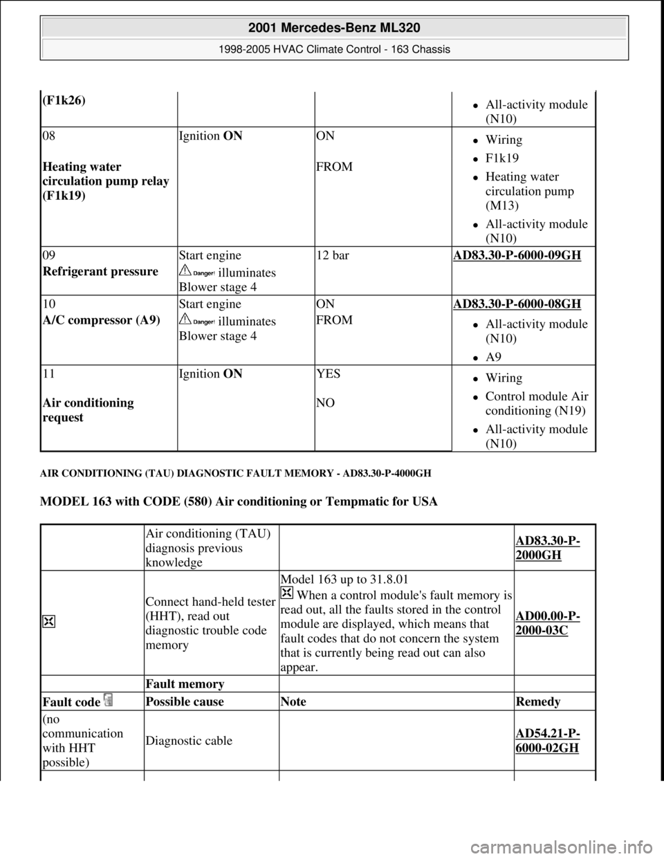
AIR CONDITIONING (TAU) DIAGNOSTIC FAULT MEMORY - AD83.30-P-4000GH
MODEL 163 with CODE (580) Air conditioning or Tempmatic for USA
(F1k26) All-activity module
(N10)
08Ignition ON ONWiring
F1k19
Heating water
circulation pump
(M13)
All-activity module
(N10)
Heating water
circulation pump relay
(F1k19) FROM
09Start engine12 barAD83.30-P-6000-09GH
Refrigerant pressure illuminates
Blower stage 4
10Start engineONAD83.30-P-6000-08GH
A/C compressor (A9) illuminates
Blower stage 4FROMAll-activity module
(N10)
A9
11Ignition ON YESWiring
Control module Air
conditioning (N19)
All-activity module
(N10)
Air conditioning
request NO
Air conditioning (TAU)
diagnosis previous
knowledge
AD83.30-P-
2000GH
Connect hand-held tester
(HHT), read out
diagnostic trouble code
memory
Model 163 up to 31.8.01
When a control module's fault memory is
read out, all the faults stored in the control
module are displayed, which means that
fault codes that do not concern the system
that is currently being read out can also
appear.
AD00.00-P-
2000-03C
Fault memory
Fault code Possible cause Note Remedy
(no
communication
with HHT
possible)
Diagnostic cable AD54.21-P-
6000-02GH
2001 Mercedes-Benz ML320
1998-2005 HVAC Climate Control - 163 Chassis
me
Saturday, October 02, 2010 3:23:17 PMPage 170 © 2006 Mitchell Repair Information Company, LLC.
Page 3428 of 4133
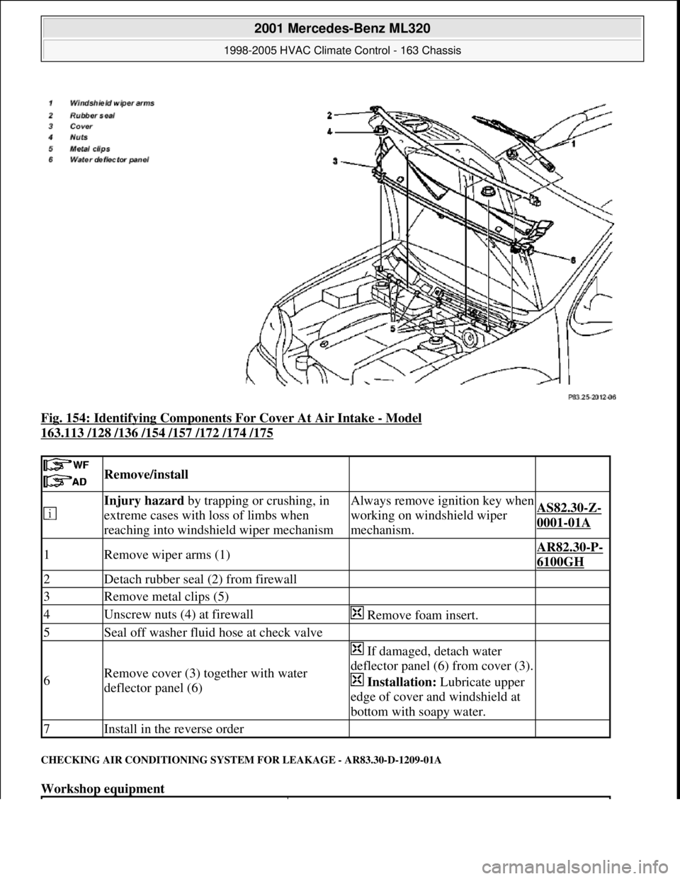
Fig. 154: Identifying Components For Cover At Air Intake - Model
163.113 /128 /136 /154 /157 /172 /174 /175
CHECKING AIR CONDITIONING SYSTEM FOR LEAKAGE - AR83.30-D-1209-01A
Workshop equipment
Remove/install
Injury hazard by trapping or crushing, in
extreme cases with loss of limbs when
reaching into windshield wiper mechanismAlways remove ignition key when
working on windshield wiper
mechanism.AS82.30-Z-
0001-01A
1Remove wiper arms (1) AR82.30-P-
6100GH
2Detach rubber seal (2) from firewall
3Remove metal clips (5)
4Unscrew nuts (4) at firewall Remove foam insert.
5Seal off washer fluid hose at check valve
6Remove cover (3) together with water
deflector panel (6)
If damaged, detach water
deflector panel (6) from cover (3).
Installation: Lubricate upper
edge of cover and windshield at
bottom with soapy water.
7Install in the reverse order
2001 Mercedes-Benz ML320
1998-2005 HVAC Climate Control - 163 Chassis
me
Saturday, October 02, 2010 3:23:18 PMPage 184 © 2006 Mitchell Repair Information Company, LLC.