1997 MERCEDES-BENZ ML430 ignition
[x] Cancel search: ignitionPage 2606 of 4133
AR47.10-P-4001GH
Emptying, filling the fuel tank
11.3.97
Model
163.136 with engine 111.977
Model
163.154 with engine 112.942
Model
163.157 with engine 112.970
Model
163.172 with engine 113.942
Model
163.174 with engine 113.981
Model
163.175 with engine 113.965
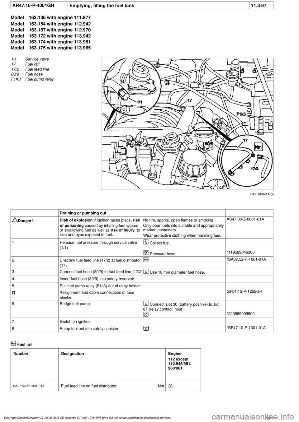
P47.10-0411-06
1/1
Service valve
17
Fuel rail
17/2
Fuel feed line
80/9
Fuel hose
F1K3
Fuel pump relay
Draining or pumping out
Danger!
Risk of explosion
if ignition takes place,
risk
of poisoning
caused by inhaling fuel vapors
or swallowing fuel as well as
risk of injury
to
skin and eyes exposed to fuel.
No fire, sparks, open flames or smoking.
Only pour fuels into suitable and appropriately
marked containers.
Wear protective clothing when handling fuel.
AS47.00-Z-0001-01A
1
Release fuel pressure through service valve
(1/1)
Collect fuel.
Pressure hose
*119589046300
2
Unscrew fuel feed line (17/2) at fuel distributor
(17)
*BA07.52-P-1001-01A
3
Connect fuel hose (80/9) to fuel feed line (17/2)
Use 10 mm diameter fuel hose.
4
Insert fuel hose (80/9) into safety reservoir
5
Pull fuel pump relay (F1k3) out of relay holder
n
Assignment and cable connections of fuse
blocks
GF54.15-P-1255GH
6
Bridge fuel pump
Connect slot 30 (battery positive) to slot
87 (relay contact input).
*220589009900
7
Switch on ignition
8
Pump fuel out into safety canister
*BF47.10-P-1001-01A
Fuel rail
Number
Designation
Engine
112 except
112.945/951/
960/961
BA07.52-P-1001-01A
Fuel feed line on fuel distributor
Nm
38
Copyright DaimlerChrysler AG 28.05.2006 CD-Ausgabe G/10/04 . This WIS print-out will not be recorde
d by Modification services.
Page 1
Page 2612 of 4133
AR47.10-P-8022GH
Remove/install fuel tank pressure sensor
18.3.97
MODEL
163.154 with ENGINE 112.942 with CODE (494a) USA version
MODEL
163.157 with ENGINE 112.970 with CODE (494a) USA version
MODEL
163.172 with ENGINE 113.942 with CODE (494a) USA version
MODEL
163.174 with ENGINE 113.981 with CODE (494a) USA version
MODEL
163.175 with ENGINE 113.965 with CODE (494a) USA version
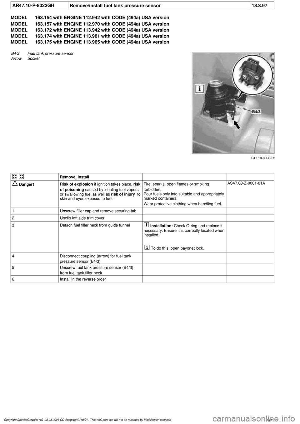
P47.10-0390-02
B4/3Fuel tank pressure sensor
Arrow
Socket
Remove, Install
Danger!
Risk of explosion
if ignition takes place,
risk
of poisoning
caused by inhaling fuel vapors
or swallowing fuel as well as
risk of injury
to
skin and eyes exposed to fuel.
Fire, sparks, open flames or smoking
forbidden.
Pour fuels only into suitable and appropriately
marked containers.
Wear protective clothing when handling fuel.
AS47.00-Z-0001-01A
1
Unscrew filler cap and remove securing tab
2
Unclip left side trim cover
3
Detach fuel filler neck from guide funnel
Installation:
Check O-ring and replace if
necessary. Ensure it is correctly located when
installed.
To do this, open bayonet lock.
4
Disconnect coupling (arrow) for fuel tank
pressure sensor (B4/3)
5
Unscrew fuel tank pressure sensor (B4/3)
from fuel tank filler neck
6
Install in the reverse order
Copyright DaimlerChrysler AG 28.05.2006 CD-Ausgabe G/10/04 . This WIS print-out will not be recorde
d by Modification services.
Page 1
Page 2855 of 4133
An excess oil level or insufficient oil level appears in the display together with the oil can symbol.
Display of low oil level at maximum:
at driver request
Display of warnings:
automatically, at the earliest 60s after engine start and oil temperature greater than 60°C:
if oil level too high: the oil can symbol appears together with the readout "OIL LEVEL ABOVE
MAX". In addition, a brief warning signal sounds. (On models not fitted with multifunction
display, "HI" appears flashing.)
if oil level too low: the oil can symbol appears together with the readout "OIL LEVEL BELOW
MIN". In addition, a brief warning signal sounds. (On models not fitted with multifunction display,
the oil level warning lamp (A1e12) comes on and the readout "-2L" appears flashing.)
if oil at minimum: the oil can symbol appears together with the readout "OIL LEVEL MINIMUM".
In addition, a brief warning signal sounds. (On models not fitted with multifunction display, the oil
level warning lamp (A1e12) comes on.)
automatically 13 s after ignition ON:
if no oil is in engine: the oil can symbol appears together with the readout "OIL LEVEL BELOW
MIN". In addition, a warning signal sounds. (On models not fitted with multifunction display, the
oil level warning lamp (A1e12) comes on and the readout "-2L" appears flashing. In addition a
brief warning signal sounds.)
The missing oil quantity displayed no longer changes during the display. In other words, any change in oil level
cannot be observed directly at the display. The new oil level is only displayed once the conditions described
below exist.
Display of oil quantity at driver request
The text "DISPLAY OIL LEVEL?" appears 10 s after the start switch has been turned into position "2" (on
models not fitted with multifunction display, the oil can and the clock symbol are displayed).
If the reset button of the trip counter is pressed twice within one sec. during this readout, for example, "add 1.0L
oil" (or "-1.0L")
appears in the display if oil level too low. The readout appears only after the elapse of a waiting time after
engine OFF. The waiting time depends on the engine oil temperature.
It is
up to 20°C 30 minutes
from 60°C 1 minute
The waiting time is between these two limits at other engine oil temperatures.
2004 Mercedes-Benz ML350
1998-2005 GENINFO Overall vehicle - 163 Chassis
me
Saturday, October 02, 2010 3:47:47 PMPage 210 © 2006 Mitchell Repair Information Company, LLC.
Page 2874 of 4133
Electric shock or direct body contact with a power source can lead to burns or scalding.
Safety instructions/precautions
Never connect the 220 V power supply to an outside socket during any repair work.
Do not touch any conductive parts of the 220 V system.
Before beginning any work always:
Disconnect the 220 V system
Ensure that the 220 V system cannot be reactivated
Ensure that no voltage is present
Ensure that the parts you are working on are grounded and short circuited
All repair work should be performed only by a trained electrician or under the direction and supervision of a
trained electrician.
Persons who wear electronic implants (e.g. heart pacemakers) must not carry out any work on such
components.
When performing any repair work on the 220 V system, proper insulated protective clothing must be worn and
insulated tools and protective devices must be used as per the safety regulations.
Observe country-specific regulations.
First aid measures
The shocked person must be immediately removed from the electric circuit.
Use protective gloves and a wood board or a wood ladder to push or move the shocked person out of the danger
zone.
First attempt to turn off the power.
Check for breathing. If there is no breathing or insufficient breathing, the preferable action is to perform
mouth-to-mouth resuscitation. If necessary, carry out CPR.
If victim is unconscious, but breathing, place victim in the recovery position.
Sterile bandages for burns.
If any of these symptoms occur, consult a physician immediately.
RISK OF DEATH CAUSED BY WORK PERFORMED ON LIQUEFIED GAS SYSTEMS - AS00.00-Z-0022-01A
Before commencing any work, ensure that all sources of ignition have been eliminated. Wear protective
2004 Mercedes-Benz ML350
1998-2005 GENINFO Overall vehicle - 163 Chassis
me
Saturday, October 02, 2010 3:47:48 PMPage 229 © 2006 Mitchell Repair Information Company, LLC.
Page 2875 of 4133
clothing, safety gloves and eye protection
Potential risks
Risk of death
Risk of explosion caused by liquefied petroleum gas leaking out of the system in closed rooms or when gas the
tank is overheated due to work being done.
Risk of burn injuries caused by explosions.
Risk of frostbite to skin and body parts caused by liquefied petroleum gas spraying out and by coming into
contact with components that are near the valve when the tank is being emptied. Risk of poisoning or risk of
suffocation caused by inhaling liquefied petroleum gas.
Safety instructions/precautions
Wear protective clothing, safety gloves and eye protection
Keep suitable fire extinguishing equipment at hand
Keep any flammable materials and objects away from the equipment
Avoid making any sparks
Perform a fire check of the surroundings after work has carried out
Never perform work in closed rooms
Before commencing any work, ensure that all sources of ignition have been eliminated. Ensure adequate
ventilation of the immediate area around the vehicle.
Adequate ventilation means an exchange of air at least 3 times an hour at a distance of 3 meters from the gas
shutoff valve.
Close the gas shutoff valves at the compressed-gas tanks before commencing repair work.
Close off gas tank valve if vehicle is to remain in closed rooms, e.g. in halls or garages, for longer periods of
time.
Maintenance and repair work may only be carried out by specially trained personnel.
Due to the fact that explosions can occur when the gas system has leaks, a leak test must be performed before
restarting the system after repairs have been done in which the pipes and lines of the gas system have been
opened.
In the Federal Republic of Germany, this leak test can only be performed by specially trained DVFG personnel
as per the DVGW Work Sheet G 607.
(DVFG - German Liquefied Petroleum Gas Association)
2004 Mercedes-Benz ML350
1998-2005 GENINFO Overall vehicle - 163 Chassis
me
Saturday, October 02, 2010 3:47:48 PMPage 230 © 2006 Mitchell Repair Information Company, LLC.
Page 2885 of 4133
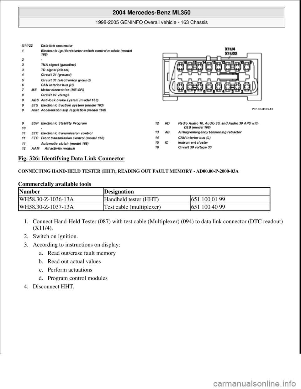
Fig. 326: Identifying Data Link Connector
CONNECTING HAND-HELD TESTER (HHT), READING OUT FAULT MEMORY - AD00.00-P-2000-03A
Commercially available tools
1. Connect Hand-Held Tester (087) with test cable (Multiplexer) (094) to data link connector (DTC readout)
(X11/4).
2. Switch on ignition.
3. According to instructions on display:
a. Read out/erase fault memory
b. Read out actual values
c. Perform actuations
d. Program control modules
4. Disconnect HHT.
NumberDesignation
WH58.30-Z-1036-13AHandheld tester (HHT)651 100 01 99
WH58.30-Z-1037-13ATest cable (multiplexer)651 100 40 99
2004 Mercedes-Benz ML350
1998-2005 GENINFO Overall vehicle - 163 Chassis
me
Saturday, October 02, 2010 3:47:48 PMPage 240 © 2006 Mitchell Repair Information Company, LLC.
Page 2886 of 4133
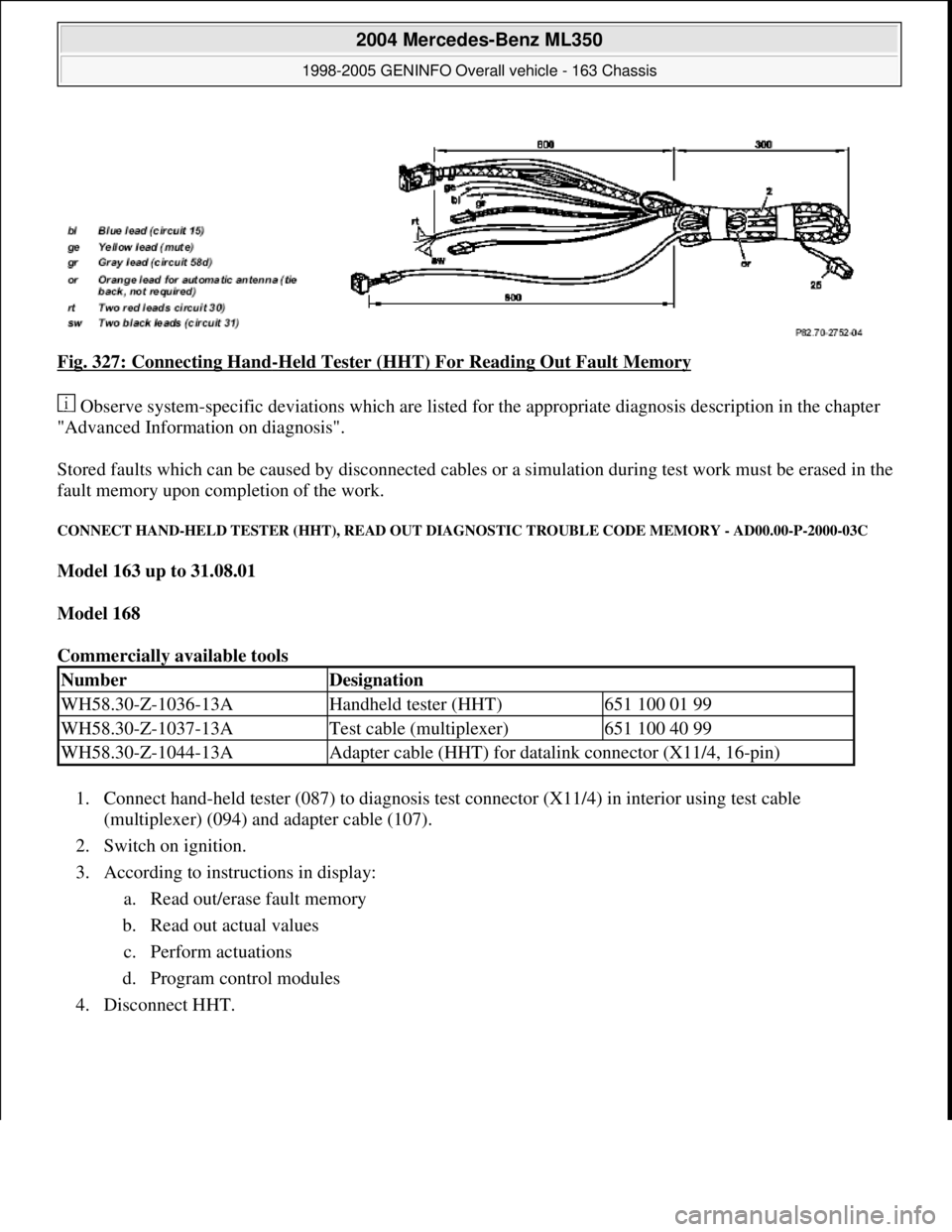
Fig. 327: Connecting Hand-Held Tester (HHT) For Reading Out Fault Memory
Observe system-specific deviations which are listed for the appropriate diagnosis description in the chapter
"Advanced Information on diagnosis".
Stored faults which can be caused by disconnected cables or a simulation during test work must be erased in the
fault memory upon completion of the work.
CONNECT HAND-HELD TESTER (HHT), READ OUT DIAGNOSTIC TROUBLE CODE MEMORY - AD00.00-P-2000-03C
Model 163 up to 31.08.01
Model 168
Commercially available tools
1. Connect hand-held tester (087) to diagnosis test connector (X11/4) in interior using test cable
(multiplexer) (094) and adapter cable (107).
2. Switch on ignition.
3. According to instructions in display:
a. Read out/erase fault memory
b. Read out actual values
c. Perform actuations
d. Program control modules
4. Disconnect HHT.
NumberDesignation
WH58.30-Z-1036-13AHandheld tester (HHT)651 100 01 99
WH58.30-Z-1037-13ATest cable (multiplexer)651 100 40 99
WH58.30-Z-1044-13AAdapter cable (HHT) for datalink connector (X11/4, 16-pin)
2004 Mercedes-Benz ML350
1998-2005 GENINFO Overall vehicle - 163 Chassis
me
Saturday, October 02, 2010 3:47:48 PMPage 241 © 2006 Mitchell Repair Information Company, LLC.
Page 2889 of 4133
Fig. 333: Connecting STAR DIAGNOSIS For Read Out Fault Memory (Illustrated On Model 171.4)
1. Connect STAR DIAGNOSIS (0100) to diagnostic socket, on the data link connector (X11/4) or on the
data link connector (1.3) (X11/22).
2. Switch on ignition.
3. Start the Diagnosis Assistance System.
4. In the "Model" menu, select the sub menu "Other model series".
5. Go through the instructions on the screen:
Enter the control unit version.
Read fault memory, erase.
Read actual values.
Perform actuations.
Adaptation of control units
6. Disconnect STAR DIAGNOSIS (0100).
Stored faults which may be caused by disconnecting cables or by simulation during testing operations must
be deleted in the diagnostic trouble code memory following completion of the operations.
EXPLANATION OF DIAGNOSTIC SYMBOLS - AD00.00-P-2001A
MODEL 124, 129, 140, 163, 168, 170, 201, 202, 208, 210, 215, 220
DIAGNOSIS ASSIGNMENT - AD00.00-P-2002A
MODEL 124, 129, 140, 163, 168, 170, 201, 202, 208, 210
CONNECT DIAGNOSIS TESTING EQUIPMENT - AD00.00-P-2003A
MODELS 124, 129, 140, 163, 168, 170, 201, 202, 203, 208, 209, 210, 220
MODELS 211.004 /006 /016 /026 /028 /042 /043 /061 /065 /070 /076 /206 /216 /226 /242 /261 /265 /616,
215.374
Explanation of symbols for
testers and components AD00.00-P-2000-01A
Assignment of data link
connectorModels 124.034/036,
129.063/067/076, 140, 170,
202, 208, 210AD00.00-P-2000-02A
Assignment of data link
connectorModel 124 except
124.034/036,
129.060/061/066, 201AD00.00-P-2000-02B
Assignment of data link
connectorModels 163, 168AD00.00-P-2000-02C
2004 Mercedes-Benz ML350
1998-2005 GENINFO Overall vehicle - 163 Chassis
me
Saturday, October 02, 2010 3:47:48 PMPage 244 © 2006 Mitchell Repair Information Company, LLC.