Page 2419 of 4133
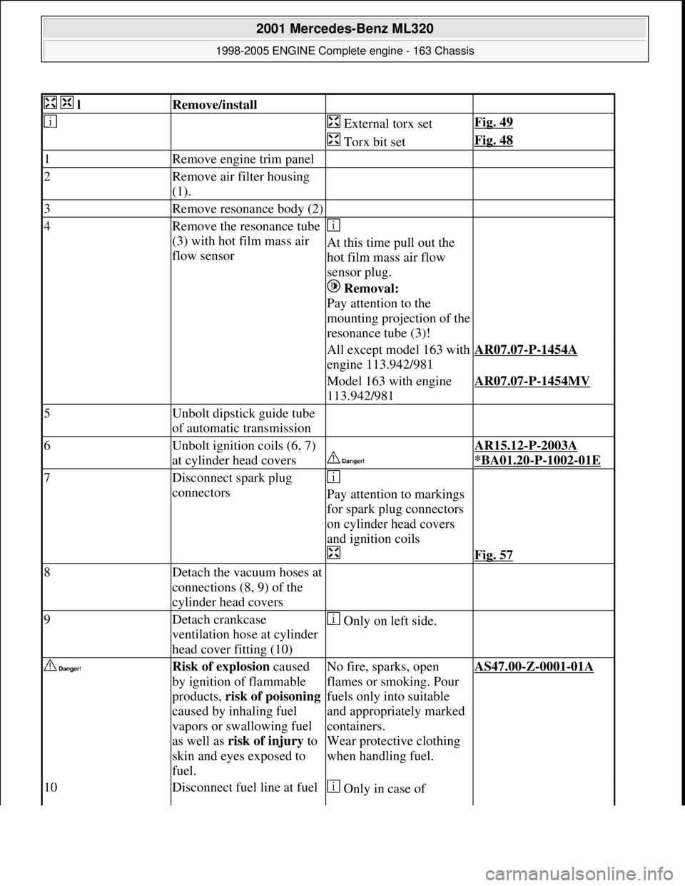
lRemove/install
External torx setFig. 49
Torx bit setFig. 48
1Remove engine trim panel
2Remove air filter housing
(1).
3Remove resonance body (2)
4Remove the resonance tube
(3) with hot film mass air
flow sensor
At this time pull out the
hot film mass air flow
sensor plug.
Removal:
Pay attention to the
mounting projection of the
resonance tube (3)!
All except model 163 with
engine 113.942/981AR07.07-P-1454A
Model 163 with engine
113.942/981AR07.07-P-1454MV
5Unbolt dipstick guide tube
of automatic transmission
6Unbolt ignition coils (6, 7)
at cylinder head covers
AR15.12-P-2003A
*BA01.20
-P-1002-01E
7Disconnect spark plug
connectors
Pay attention to markings
for spark plug connectors
on cylinder head covers
and ignition coils
Fig. 57
8Detach the vacuum hoses at
connections (8, 9) of the
cylinder head covers
9Detach crankcase
ventilation hose at cylinder
head cover fitting (10) Only on left side.
Risk of explosion caused
by ignition of flammable
products, risk of poisoning
caused by inhaling fuel
vapors or swallowing fuel
as well as risk of injury to
skin and eyes exposed to
fuel.No fire, sparks, open
flames or smoking. Pour
fuels only into suitable
and appropriately marked
containers.
Wear protective clothing
when handling fuel.AS47.00-Z-0001-01A
10Disconnect fuel line at fuel Only in case of
2001 Mercedes-Benz ML320
1998-2005 ENGINE Complete engine - 163 Chassis
me
Saturday, October 02, 2010 3:17:56 PMPage 63 © 2006 Mitchell Repair Information Company, LLC.
Page 2420 of 4133
Crankcase ventilation, cylinder head cover
Fuel rail
railvehicles with a non-
flexible fuel line.
Release fuel pressure
through service valve!
Pressure hoseFig. 52
*BA07.52-P-1001-01A
*BA07.52-P-1001-01A
11Remove cylinder head
covers (4, 5) *BA01.20-P-1001-01E
Installation:
Ensure cylinder head
cover gasket is correctly
installed.AR01.20-P-5014-01B
12Install in the reverse order
13Risk of accident caused by
vehicle starting off by itself
when engine is running.
Risk of injury caused by
contusions and burns during
starting procedure or when
working near the running
engine
Run engine and inspect for
leaksSecure vehicle to prevent
it from moving by itself.
Wear closed and snug-
fitting work clothes.
Do not grasp hot or
rotating parts.AS00.00-Z-0005-01A
NumberDesignation
Engine 112.910/911/
912/913/914/ 915/916/917/
920/921/922/ 923/940/941/
942/943/944/ 945/946/947/
949/951/953/ 954/955/960/
961/970/972/ 973/975/976Engines 113.940/
941/942/943/ 944/948/960/
961/962/963/ 964/965/966/
967/968/969/ 971/980/981/
982/984/986/ 992/995
Engine
113.987/988/
990/991/993
BA01.20-
P-1001-
01EScrew of
cylinder
head cover
Nm8108
BA01.20-
P-1002-
01E
Bolt of
ignition
coils to
cylinder
head cover
Nm888
NumberDesignationEngine 112 except
112.945/951/ 960/961Engine
112.945Engine
112.960/ 976Engine
112.960/ 961
AMG
2001 Mercedes-Benz ML320
1998-2005 ENGINE Complete engine - 163 Chassis
me
Saturday, October 02, 2010 3:17:56 PMPage 64 © 2006 Mitchell Repair Information Company, LLC.
Page 2423 of 4133
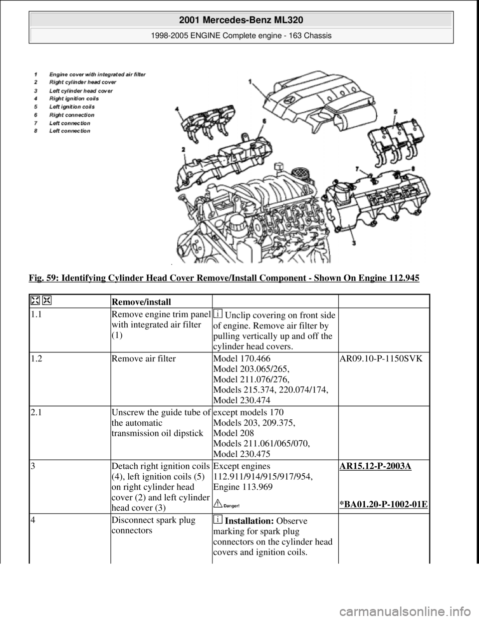
Fig. 59: Identifying Cylinder Head Cover Remove/Install Component - Shown On Engine 112.945
Remove/install
1.1Remove engine trim panel
with integrated air filter
(1) Unclip covering on front side
of engine. Remove air filter by
pulling vertically up and off the
cylinder head covers.
1.2Remove air filterModel 170.466
Model 203.065/265,
Model 211.076/276,
Models 215.374, 220.074/174,
Model 230.474AR09.10-P-1150SVK
2.1Unscrew the guide tube of
the automatic
transmission oil dipstickexcept models 170
Models 203, 209.375,
Model 208
Models 211.061/065/070,
Model 230.475
3Detach right ignition coils
(4), left ignition coils (5)
on right cylinder head
cover (2) and left cylinder
head cover (3)Except engines
112.911/914/915/917/954,
Engine 113.969AR15.12-P-2003A
*BA01.20-P-1002-01E
4Disconnect spark plug
connectors Installation: Observe
marking for spark plug
connectors on the cylinder head
covers and ignition coils.
2001 Mercedes-Benz ML320
1998-2005 ENGINE Complete engine - 163 Chassis
me
Saturday, October 02, 2010 3:17:56 PMPage 67 © 2006 Mitchell Repair Information Company, LLC.
Page 2425 of 4133
Crankcase ventilation, cylinder head cover
Fuel rail
Fuel rail
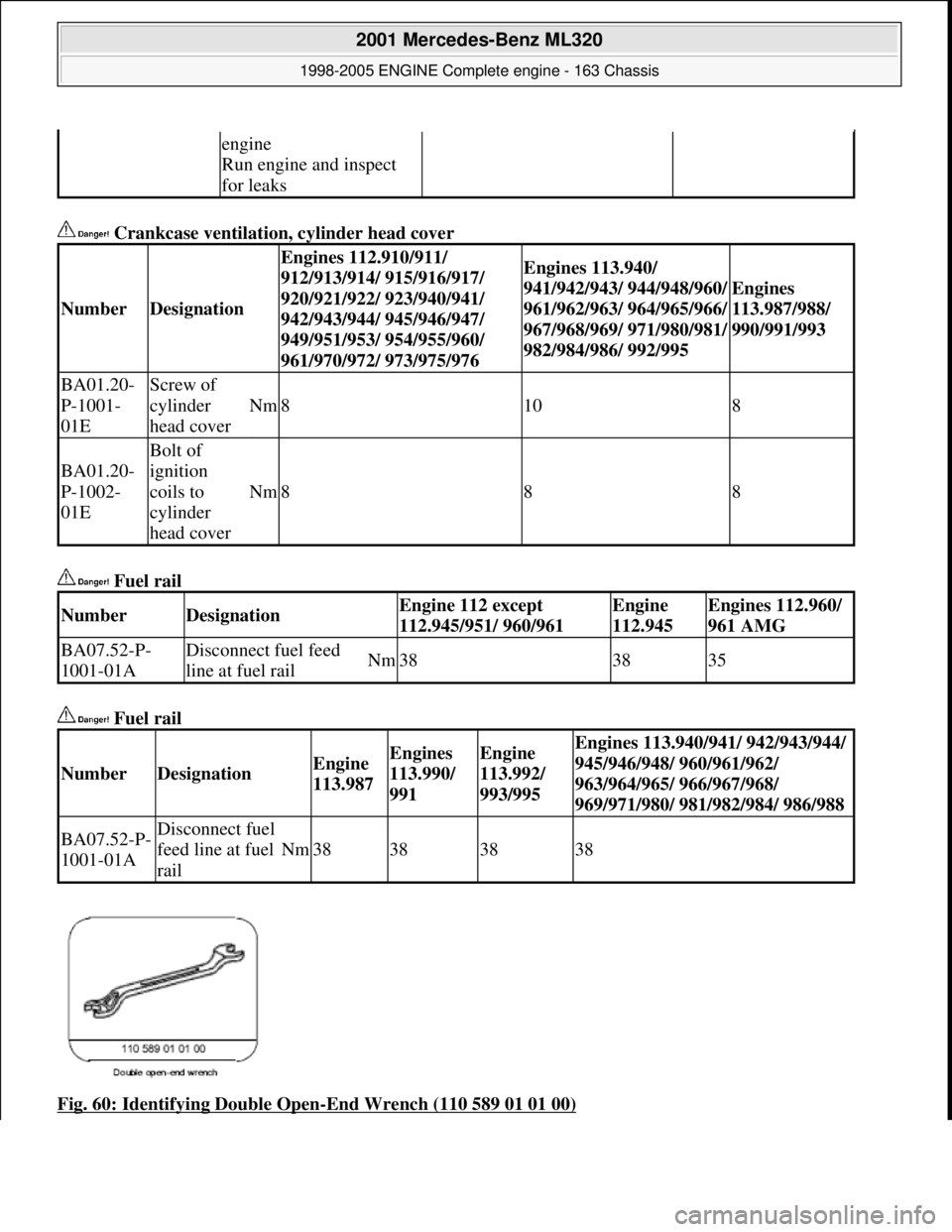
Fig. 60: Identifying Double Open
-End Wrench (110 589 01 01 00)
engine
Run engine and inspect
for leaks
NumberDesignation
Engines 112.910/911/
912/913/914/ 915/916/917/
920/921/922/ 923/940/941/
942/943/944/ 945/946/947/
949/951/953/ 954/955/960/
961/970/972/ 973/975/976Engines 113.940/
941/942/943/ 944/948/960/
961/962/963/ 964/965/966/
967/968/969/ 971/980/981/
982/984/986/ 992/995
Engines
113.987/988/
990/991/993
BA01.20-
P-1001-
01EScrew of
cylinder
head cover
Nm8108
BA01.20-
P-1002-
01E
Bolt of
ignition
coils to
cylinder
head cover
Nm888
NumberDesignationEngine 112 except
112.945/951/ 960/961Engine
112.945Engines 112.960/
961 AMG
BA07.52-P-
1001-01ADisconnect fuel feed
line at fuel railNm383835
NumberDesignationEngine
113.987Engines
113.990/
991Engine
113.992/
993/995Engines 113.940/941/ 942/943/944/
945/946/948/ 960/961/962/
963/964/965/ 966/967/968/
969/971/980/ 981/982/984/ 986/988
BA07.52-P-
1001-01ADisconnect fuel
feed line at fuel
rail
Nm38383838
2001 Mercedes-Benz ML320
1998-2005 ENGINE Complete engine - 163 Chassis
me
Saturday, October 02, 2010 3:17:56 PMPage 69 © 2006 Mitchell Repair Information Company, LLC.
Page 2443 of 4133
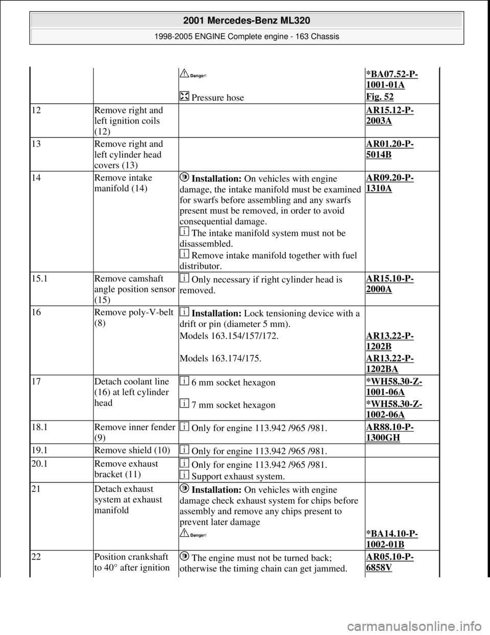
*BA07.52-P-
1001-01A
Pressure hoseFig. 52
12Remove right and
left ignition coils
(12) AR15.12-P-
2003A
13Remove right and
left cylinder head
covers (13) AR01.20-P-
5014B
14Remove intake
manifold (14) Installation: On vehicles with engine
damage, the intake manifold must be examined
for swarfs before assembling and any swarfs
present must be removed, in order to avoid
consequential damage.
The intake manifold system must not be
disassembled.
Remove intake manifold together with fuel
distributor.AR09.20-P-
1310A
15.1Remove camshaft
angle position sensor
(15) Only necessary if right cylinder head is
removed.AR15.10-P-
2000A
16Remove poly-V-belt
(8) Installation: Lock tensioning device with a
drift or pin (diameter 5 mm).
Models 163.154/157/172.AR13.22-P-
1202B
Models 163.174/175.AR13.22-P-
1202BA
17Detach coolant line
(16) at left cylinder
head 6 mm socket hexagon*WH58.30-Z-
1001-06A
7 mm socket hexagon*WH58.30-Z-
1002-06A
18.1Remove inner fender
(9) Only for engine 113.942 /965 /981.AR88.10-P-
1300GH
19.1Remove shield (10) Only for engine 113.942 /965 /981.
20.1Remove exhaust
bracket (11) Only for engine 113.942 /965 /981.
Support exhaust system.
21Detach exhaust
system at exhaust
manifold Installation: On vehicles with engine
damage check exhaust sy stem for chips before
assembly and remove any chips present to
prevent later damage
*BA14.10-P-
1002-01B
22Position crankshaft
to 40° after ignition The engine must not be turned back;
otherwise the timing chain can get jammed. AR05.10-P-
6858V
2001 Mercedes-Benz ML320
1998-2005 ENGINE Complete engine - 163 Chassis
me
Saturday, October 02, 2010 3:17:57 PMPage 87 © 2006 Mitchell Repair Information Company, LLC.
Page 2489 of 4133
Oil pan
Fig. 107: Identifying External Torx Set (001 589 76 09 00)
Repair materials
REMOVE/INSTALL BOTTOM PART OF OIL PAN - AR01.45-P-7555V
ENGINE 112.942 in MODEL 163.154
ENGINE 112.970 in MODEL 163.157
ENGINE 113.942 in MODEL 163.172
BA01.20-P-
1002-01EBolt of ignition
coils to cylinder
head coverNm888
NumberDesignation
Engine
112.910/911/
912/913/914/
915/917/920/
921/922/923/
940/941/942/
943/944/945/
946/947/949/
951/954/955/
960/961/970/
972/973/976
Engine
113.940/941/
942/943/944/
945/946/960/
961/962/963/
965/967/968/
969/980/981/
982/984/986/
992/995
BA01.45-P-
1001-01BBolt, oil pan to
crankcaseM6Nm99
M8Nm2020
BA01.45-P-
1002-01BSelf-tapping
screw of oil pan
to oil panThread not pre-
tappedNm1414
Thread pre-
tappedNm1010
NumberDesignationOrder number
BR00.45-Z-1013-01ASealantA 003 989 98 20
2001 Mercedes-Benz ML320
1998-2005 ENGINE Complete engine - 163 Chassis
me
Saturday, October 02, 2010 3:17:58 PMPage 133 © 2006 Mitchell Repair Information Company, LLC.
Page 2511 of 4133
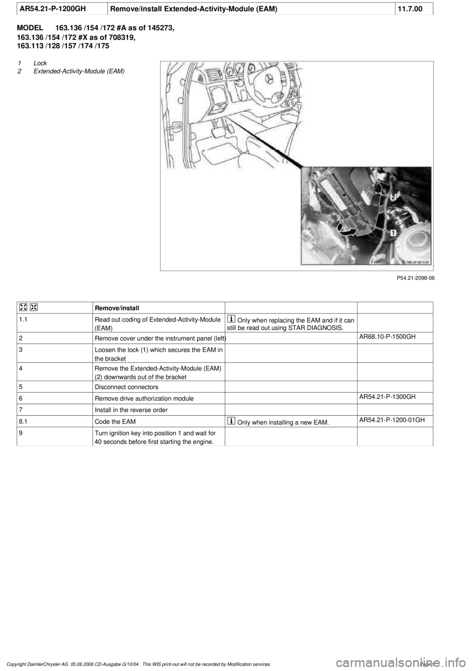
AR54.21-P-1200GH
Remove/install Extended-Activity-Module (EAM)
11.7.00
MODEL
163.136 /154 /172 #A as of 145273,
163.136 /154 /172 #X as of 708319,
163.113 /128 /157 /174 /175
P54.21-2098-06
1
Lock
2
Extended-Activity-Module (EAM)
Remove/install
1.1
Read out coding of Extended-Activity-Module
(EAM)
Only
when replacing the EAM and if it can
still be read out using STAR DIAGNOSIS.
2
Remove cover under the instrument panel (left)
AR68.10-P-1500GH
3
Loosen the lock (1) which secures the EAM in
the bracket
4
Remove the Extended-Activity-Module (EAM)
(2) downwards out of the bracket
5
Disconnect connectors
6
Remove drive authorization module
AR54.21-P-1300GH
7
Install in the reverse order
8.1
Code the EAM
Only
when installing a new EAM.
AR54.21-P-1200-01GH
9
Turn ignition key into position 1 and wait for
40 seconds before first starting the engine.
Copyright DaimlerChrysler AG 05.06.2006 CD-Ausgabe G/10/04 . This WIS print-out will not be recorde
d by Modification services.
Page 1
Page 2524 of 4133
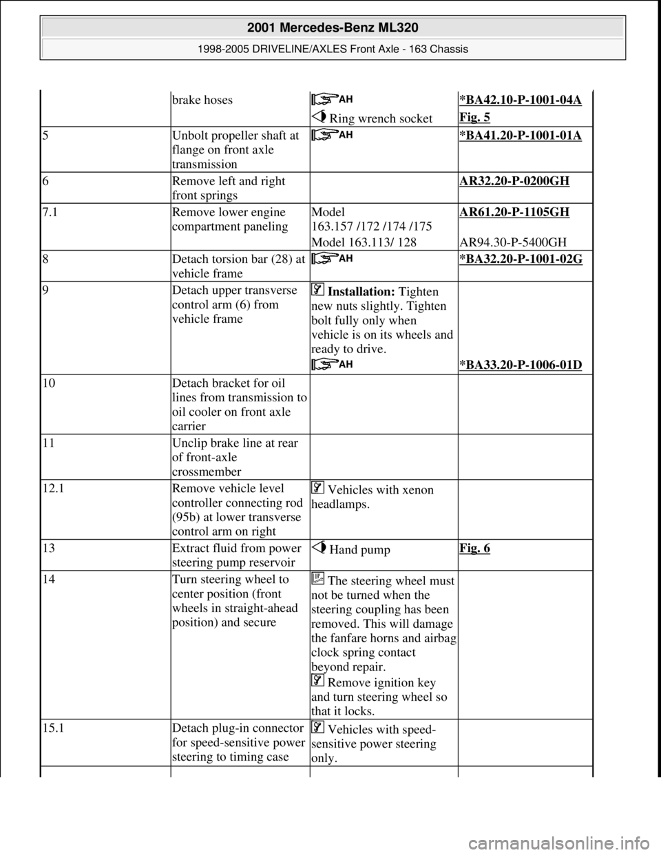
brake hoses *BA42.10-P-1001-04A
Ring wrench socketFig. 5
5Unbolt propeller shaft at
flange on front axle
transmission *BA41.20-P-1001-01A
6Remove left and right
front springs AR32.20-P-0200GH
7.1Remove lower engine
compartment panelingModel
163.157 /172 /174 /175AR61.20-P-1105GH
Model 163.113/ 128AR94.30-P-5400GH
8Detach torsion bar (28) at
vehicle frame *BA32.20-P-1001-02G
9Detach upper transverse
control arm (6) from
vehicle frame Installation: Tighten
new nuts slightly. Tighten
bolt fully only when
vehicle is on its wheels and
ready to drive.
*BA33.20-P-1006-01D
10Detach bracket for oil
lines from transmission to
oil cooler on front axle
carrier
11Unclip brake line at rear
of front-axle
crossmember
12.1Remove vehicle level
controller connecting rod
(95b) at lower transverse
control arm on right Vehicles with xenon
headlamps.
13Extract fluid from power
steering pump reservoir Hand pumpFig. 6
14Turn steering wheel to
center position (front
wheels in straight-ahead
position) and secureThe steering wheel must
not be turned when the
steering coupling has been
removed. This will damage
the fanfare horns and airbag
clock spring contact
beyond repair.
Remove ignition key
and turn steering wheel so
that it locks.
15.1Detach plug-in connector
for speed-sensitive power
steering to timing case Vehicles with speed-
sensitive power steering
only.
2001 Mercedes-Benz ML320
1998-2005 DRIVELINE/AXLES Front Axle - 163 Chassis
me
Saturday, October 02, 2010 3:38:21 PMPage 5 © 2006 Mitchell Repair Information Company, LLC.