1997 MERCEDES-BENZ ML430 ignition
[x] Cancel search: ignitionPage 3224 of 4133
blend air flap actuator motor.
6. Turn ignition off. Disconnect test cable from A/C push button control unit. Connect ohmmeter positive
lead to socket box terminal No. 1 and negative lead to terminal No. 8. Resistance should be 120 ohms.
7. If resistance is not as specified, check blend air flap actuator motor circuits. See WIRING DIAGRAMS
.
Repair as necessary. If circuits are okay, replace blend air flap actuator motor.
A/C Button
1. Connect socket box to A/C push button control unit and wiring harness. See CONNECTING TEST
EQUIPMENT . Connect voltmeter positive lead to socket box terminal No. 10 and negative lead to
terminal No. 9.
2. Turn ignition on. Depress A/C button switch to on position and set blower speed knob to position No. 4.
Ensure A/C button indicator is illuminated. Voltage should be less than one volt. Depress A/C button
switch to off position with A/C button indicator not illuminated or set blower speed knob to off position.
Voltage should be 11-14 volts.
3. If voltage is as specified, go to next step. If voltage is not as specified, check A/C button wiring harness
circuits. See WIRING DIAGRAMS
. Repair as necessary. If circuits are okay, replace A/C button
switch.
4. Turn ignition on. Depress A/C button switch to on position and set blower speed knob to position No. 4.
Ensure A/C button indicator is illuminated. Connect voltmeter positive lead to socket box terminal No. 4
and negative lead to terminal No. 9. Voltage should be more than 3.0 volts.
5. Connect Fused Jumper Wire (124 589 37 63 00) between socket box terminals No. 4 and 11. Depress A/C
button switch to on position and set blower speed knob to position No. 4. Ensure A/C button indicator is
illuminated. Measure voltage. Voltage should be less than one volt.
6. If voltage is not as specified, check A/C button wiring harness circuits. See WIRING DIAGRAMS
.
Repair as necessary. If circuits are okay, replace A/C button switch.
A/C Refrigerant Pressure Switch
1. Turn ignition off. Disconnect refrigerant pressure sensor connector. Turn ignition on. Connect voltmeter
positive lead to pressure sensor harness connector terminal "B" (Pink wire) and negative lead to terminal
"A" (Tan wire). Voltage should be 4.75-5.25 volts.
2. If voltage is as specified, replace A/C refrigerant pressure sensor. If voltage is not as specified, check
wiring harness between refrigerant pressure sensor and All Activity Module (AAM). See WIRING
DIAGRAMS . Repair as necessary. If circuits are okay, replace AAM and retest A/C system.
Outside Temperature Sensor
1. Connect socket box to A/C push button control unit and wiring harness. See CONNECTING TEST
EQUIPMENT . Turn ignition off. Connect ohmmeter positive lead to socket box terminal No. 12 and
negative lead to terminal No. 3.
2. Disconnect test cable from A/C push button control unit. See OUTSIDE TEMPERATURE SENSOR
RESISTANCE table. If resistance is not as specified, check wiring harness between outside temperature
sensor and A/C push button control unit. See WIRING DIAGRAMS
. Repair as necessary. If wiring
harness is okay, replace outside temperature sensor.
2001 Mercedes-Benz ML320
2000-01 MANUAL A/C-HEATER SYSTEMS ML 320, ML 430 & ML 55
me
Saturday, October 02, 2010 3:25:10 PMPage 13 © 2006 Mitchell Repair Information Company, LLC.
Page 3225 of 4133
OUTSIDE TEMPERATURE SENSOR RESISTANCE
READING ACTUAL VALUES WITH HHT
Connect Hand-Held Tester (HHT) to DLC and follow displayed procedures. Actual values displayed on HHT
show normal operation value of A/C systems or components. See ACTUAL VALUES
table. If value is not as
specified, check system or components in order. Repair as necessary.
ACTUAL VALUES
REMOVAL & INSTALLATION
Sensor Temperature - °F (°C)Ohms
68 (20)2100
77 (25)1700
104 (40)900
122 (50)600
Step (1) Test ConditionValueSystem/Component
01.....11-14 VoltsVoltage Supply Wiring (Circuit
No. 30) & Battery
02Engine Operating At
Normal TemperatureAbout 176°F (80°C)Wiring, ECT Sensor & AAM
03Ignition ONAmbient Air Temperature
About 68°F (20°C)Wiring, Outside Temperature
Sensor & AAM
04Ignition ON, Blower At
Stage 4ON/OFFWiring, Blower Motor Relay,
Blower Motor & AAM
05Ignition ONON/OFFWiring, Engine Cooling Fan
Stage 1, Aux. Fan & AAM
08Ignition ONON/OFFWiring, Coolant Circulation Pump
Relay, Coolant Circulation Pump
& AAM
09Engine On, A/C Indicator
On, Blower Motor At
Stage 4Refrigerant Pressure At
174 psi (12 bar)(2) Refrigerant Pressure Sensor
10Engine On, A/C Indicator
On, Blower Motor At
Stage 4ON/OFF(3) AAM, A/C Compressor
11Ignition ON, Activate
A/C SystemYES/NOWiring, A/C Push Button Control
Module, AAM
(1)Step numbers not shown are not used.
(2)Check A/C refrigerant pressure switch. See A/C REFRIGERANT PRESSURE SWITCH under
ELECTRICAL TESTS.
(3)Check A/C button activation. See A/C BUTTON under ELECTRICAL TESTS.
2001 Mercedes-Benz ML320
2000-01 MANUAL A/C-HEATER SYSTEMS ML 320, ML 430 & ML 55
me
Saturday, October 02, 2010 3:25:10 PMPage 14 © 2006 Mitchell Repair Information Company, LLC.
Page 3289 of 4133
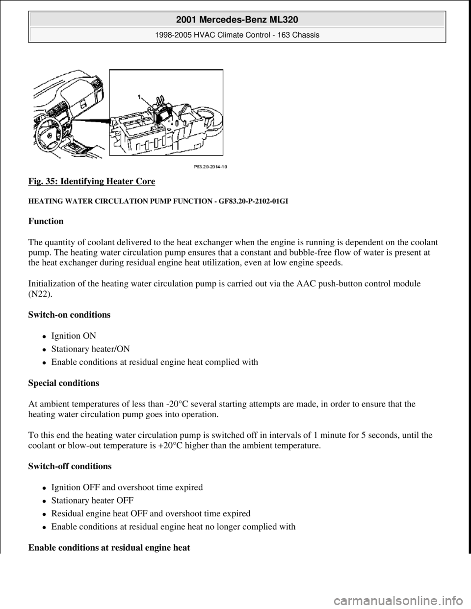
Fig. 35: Identifying Heater Core
HEATING WATER CIRCULATION PUMP FUNCTION - GF83.20-P-2102-01GI
Function
The quantity of coolant delivered to the heat exchanger when the engine is running is dependent on the coolant
pump. The heating water circulation pump ensures that a constant and bubble-free flow of water is present at
the heat exchanger during residual engine heat utilization, even at low engine speeds.
Initialization of the heating water circulation pump is carried out via the AAC push-button control module
(N22).
Switch-on conditions
Ignition ON
Stationary heater/ON
Enable conditions at residual engine heat complied with
Special conditions
At ambient temperatures of less than -20°C several starting attempts are made, in order to ensure that the
heating water circulation pump goes into operation.
To this end the heating water circulation pump is switched off in intervals of 1 minute for 5 seconds, until the
coolant or blow-out temperature is +20°C higher than the ambient temperature.
Switch-off conditions
Ignition OFF and overshoot time expired
Stationary heater OFF
Residual engine heat OFF and overshoot time expired
Enable conditions at residual engine heat no longer complied with
Enable conditions at residual engine heat
2001 Mercedes-Benz ML320
1998-2005 HVAC Climate Control - 163 Chassis
me
Saturday, October 02, 2010 3:23:15 PMPage 45 © 2006 Mitchell Repair Information Company, LLC.
Page 3325 of 4133
The residual engine heat utilization system allows the vehicle to be heated even when the ignition is
switched OFF. To do so the system utilizes the residual heat from the engine and guides it via the
blower into the passenger compartment. The heating water circulation pump ensures that the
coolant is properly circulated.
Automatic air conditioning push-button control module
The automatic air conditioning can be operated by the driver using various tip switches. Apart from this
the push-
button control module reads in different sensor signals, processes them and controls components
in the automatic air conditioning.
Rear ventilation control panel
The operator can intervene in the automatic regulation of the rear ventilation through the automatic air
conditioning by using the rear ventilation control panel and adjust it accordingly to suit needs at any
given time. With the aid of the air distribution switch and blower switch the operator can accommodate
his/her own wishes. The correspondingly altered function is then no longer regulated by the automatic air
conditioning.
By pressing the automatic control button the manually initiated settings can be reset and thus regulated
again by the automatic air conditioning.
Regulation of the air quantity and air distribution ensues thus solely by way of the automatic air
conditioning push-button control module.
Heater circuit
Coolant is heated by the engine. Subsequently, the heated coolant is then routed through the heat exchanger,
where the heat is dissipated to the air in the passenger compartment. The heater return line, in which the heating
water circulation pump is located, takes the coolant back to the coolant pump.
The heating water circulation pump ensures that the coolant is properly circulated.
The coolant flows through the heat exchanger permanently.
Depending upon the desired in-car temperature, regulation is conducted over the blending air flaps, which are
operated by the blending air flap actuator motor.
Heater operation with heater booster in vehicles with OM 612.963
In vehicles equipped with direct-injection diesel engines, an electrical heater booster is additionally installed in
the evaporator housing downstream of the heat exchanger, in order to compensate the heater output deficit
which occurs in the case of certain operating conditions.
The 3 heating elements in the heater booster are supplied with current, as a result of which they are heated and
start to glow. As a result of the structural conditions, it is ensured that the drawn in fresh air flows directly past
the electric heater booster, and is therefore heated.
2001 Mercedes-Benz ML320
1998-2005 HVAC Climate Control - 163 Chassis
me
Saturday, October 02, 2010 3:23:16 PMPage 81 © 2006 Mitchell Repair Information Company, LLC.
Page 3327 of 4133
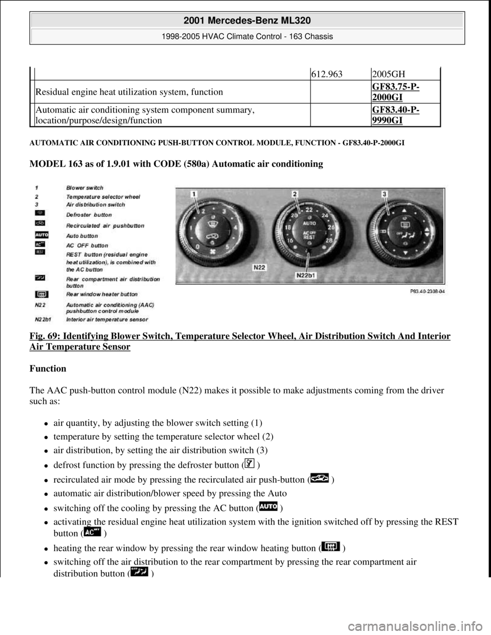
AUTOMATIC AIR CONDITIONING PUSH-BUTTON CONTROL MODULE, FUNCTION - GF83.40-P-2000GI
MODEL 163 as of 1.9.01 with CODE (580a) Automatic air conditioning
Fig. 69: Identifying Blower Switch , Temperature Selector Wheel, Air Di stribution Switch And Interior
Air Temperature Sensor
Function
The AAC push-button control module (N 22) makes it possible to make adjustments coming from the driver
such as:
air quantity, by adjusting the blower switch setting (1)
temperature by setting the temp erature selector wheel (2)
air distribution, by setting the air distribution switch (3)
defrost function by pressing the defroster button ( )
recirculated air mode by pressing th e recirculated air push-button ( )
automatic air distribution/blower speed by pressing the Auto
switching off the cooling by pressing the AC button ( )
activating the residual engine heat ut ilization system with the ignition switched of f by pressing the REST
button ( )
heating the rear window by pressing the rear window heating button ( )
switching off the air distribution to the rear compartment by pressing the rear compartment air
distribution button ( )
612.9632005GH
Residual engine heat util ization system, function GF83.75-P-
2000GI
Automatic air conditioning sy stem component summary,
location/purpose/design/function GF83.40-P-
9990GI
2001 Mercedes-Benz ML320
1998-2005 HVAC Climate Control - 163 Chassis
me
Saturday, October 02, 2010 3:23:16 PMPage 83 © 2006 Mitchell Repair Information Company, LLC.
Page 3334 of 4133
Air distribution button ( ) = air duc ting to rear compartment nozzle
Air distribution button ( ) = air ducting to the air outlets in the rear footwell
The automatic air distribution function can be set by pr essing the Auto button, whereby control is assumed by
the AAC push-button c ontrol module (N22).
RECIRCULATING AIR PU SH-BUTTON, FUNCTION - GF83.40-P-2102-01GI
Function
A brief actuation (< 1.5 s) of the recirculating air pus h-button ( ) energizes the actuator motor for the fresh
air/recirculated air flap, whic h activates the fresh air/recirculated air fl ap and thus closes the fresh air duct and
opens the recirculation duct, in or der to enable the air supply from the passenger compartment. The function
LED illuminates during recirculation mode.
Recirculated air convenience closing function
If the recirculating air pus h-button ( ) is pressed for longer than > 2 s, then alongside the recirculation
function, all open windows and the sliding and tilting roof are automatically closed (window and sliding/
tilting roof must ha ve been normalized ). The function LED illuminates durin g recirculation mode. In order to
prevent any current peaks the sliding/tilting sunroof and power windows are actuated successively.
If the push-button is pressed again for > 2 s, the windows a nd the sliding/tilting sunroof return to the previously
stored position and the fresh air/ recirculated air flap moves to the fresh air position (LED off).
The convenience closing function can only be started if the recirculating LED is not illuminated.
Each window, which has been manually opened during the r ecirculation phase, remains in this position if the
recirculating function is cleared: all other windows move to the stor ed positions. The position of the
sliding/tilting sunroof prior to the st art of the closing operation and that of the side windows is stored in the
memory. The windows and the sliding/tilting sunroof wh ich have been closed by the convenience closing
function, remain closed if the recirculation push-
button was only pressed briefly (t < 1.5 s). In this case, only the
fresh air/recirculated air flap is moved to the fresh-air position. The stored positions are cleared when the
ignition is switched off.
AUTOMATIC AIR CONDITIONING BOX FUNCTION - GF83.40-P-2105-02GI
Operating condition: Air ducting under heater operation
2001 Mercedes-Benz ML320
1998-2005 HVAC Climate Control - 163 Chassis
me
Saturday, October 02, 2010 3:23:16 PMPage 90 © 2006 Mitchell Repair Information Company, LLC.
Page 3341 of 4133
REST BUTTON, FUNCTION - GF83.40-P-2109-01GI
Function
Pressing the reset button ( ) on the AAC push-button control module (N22) switches on the residual engine
heat utilization system. When the engine is switched off, the residual heat heats the vehicle depending on the
temperature setting on the AAC push-button control panel (N22) and the ambient temperature in the vehicle
interior. The vehicle can be heated for approx. 30 min, with the engine switched off. The function is only
available with the ignition switched off or in position 1. If there is low voltage, the residual heat function is
automatically switched off.
The flaps are in automatic mode and the quantity of air is also automatically regulated.
The residual heat function is switched off,
if the electronic key is moved to position 2 in the starter switch,
after approx. 30 minutes,
if the battery voltage drops below 11V.
AUXILIARY FAN, FUNCTION - GF83.40-P-2115-01GH
Function
Depending on the refrigerant pressure and/or the coolant temperature the left auxiliary fan (M4m1), right
auxiliary fan (M4m2) are actuated.
The all-activity module (AAM) (N10) receives the coolant temperature from the coolant temperature sensor and
the refrigerant pressure from the refrigerant pressure sensor (B12).
The all-activity module (AAM) (N10) compares this input information with stored values and actuates the left
auxiliary fan (M4m1), right auxiliary fan (M4m2).
When the following values are indicated the left auxiliary fan (M4m1), right auxiliary fan (M4m2) are switched
on or off:
refrigerant pressure >16 bar = auxiliary fan ON
refrigerant pressure < 12 bar = auxiliary fan OFF
coolant temperature > 105°C = auxiliary fan ON
coolant temperature < 94°C = auxiliary fan OFF
AUXILIARY FAN, FUNCTION - GF83.40-P-2115-01GI
Function
Depending on the refrigerant pressure and/or the coolant temperature the left auxiliary fan (M4m1) and the right
auxiliary fan (M4m2) are actuated.
2001 Mercedes-Benz ML320
1998-2005 HVAC Climate Control - 163 Chassis
me
Saturday, October 02, 2010 3:23:16 PMPage 97 © 2006 Mitchell Repair Information Company, LLC.
Page 3385 of 4133
The in-car temperature sensor (B10/4) is equipped with an aspirator blower which constantly draws air out of
the vehicle interior for the temperature measurement when the ignition is ON . The in-car temperature sensor
(B10/4) records the interior temperature and conveys it to the AAC push-button control module. A comparison
is made there with the setting on the temperature selector and the blend air flap is repositioned depending on the
result of this comparison.
It is connected to the AAC push-button control module via a separate electric cable.
Constant circulation of the interior air at the in-car temperature sensor (B10/4) is achieved by the in-car
temperature sensor aspirator blower (M9) and therefore ensures a high level of control accuracy.
In contrast to the previous suction jet nozzle a high level of control accuracy is ensured by the in-car
temperature sensor aspirator blower (M9).
OUTSIDE AIR TEMPERATURE SENSOR FUNCTION - GF83.57-P-2103-01GH
Function
The resistance of the outside air temperature sensor (B10/5) depends on the ambient temperature and the ground
speed. With an increase in the outside temperature, its resistance decreases. This information is sent to the air
conditioning control module (N19). This information causes a slight lowering or raising of the temperature
selected at the air conditioning control panel.
This achieves an adaptation to the temperature perception of the occupants.
The outside temperature depends on the ground speed, which prevents a value for the outside temperature that is
too high - as may occur when the vehicle is stationary or when traveling slowly, e.g. due to thermal radiation
from the engine - from being sent to the air conditioning control module (N19).
The value of the ground speed is sent from the traction systems control module (N47) via the instrument cluster
(A1) to the air conditioning control module (N19).
When switching the ignition off and on and with speeds lower than 20 km/h the temperature measured last is
used.
OUTSIDE AIR TEMPERATURE SENSOR POSITION - GF83.57-P-2103-02GH
The outside air temperature sensor (B10/5) is located at the front on the air inlet of the evaporator housing.
2001 Mercedes-Benz ML320
1998-2005 HVAC Climate Control - 163 Chassis
me
Saturday, October 02, 2010 3:23:17 PMPage 141 © 2006 Mitchell Repair Information Company, LLC.