1997 MERCEDES-BENZ ML430 ignition
[x] Cancel search: ignitionPage 3441 of 4133

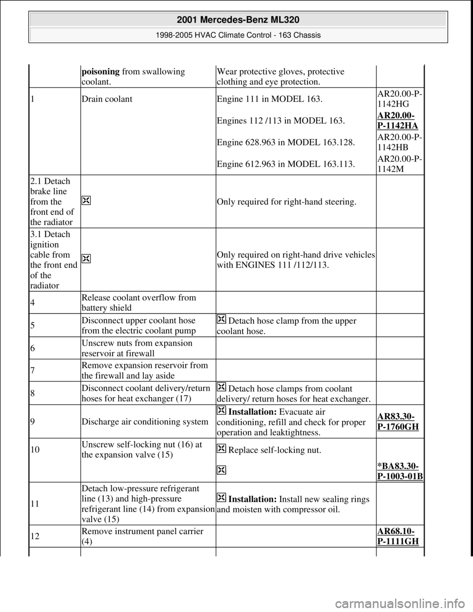
poisoning from swallowing
coolant.Wear protective gloves, protective
clothing and eye protection.
1Drain coolantEngine 111 in MODEL 163.AR20.00-P-
1142HG
Engines 112 /113 in MODEL 163.AR20.00-
P-1142HA
Engine 628.963 in MODEL 163.128.AR20.00-P-
1142HB
Engine 612.963 in MODEL 163.113.AR20.00-P-
1142M
2.1 Detach
brake line
from the
front end of
the radiator
Only required for right-hand steering.
3.1 Detach
ignition
cable from
the front end
of the
radiator
Only required on right-hand drive vehicles
with ENGINES 111 /112/113.
4Release coolant overflow from
battery shield
5Disconnect upper coolant hose
from the electric coolant pump Detach hose clamp from the upper
coolant hose.
6Unscrew nuts from expansion
reservoir at firewall
7Remove expansion reservoir from
the firewall and lay aside
8Disconnect coolant delivery/return
hoses for heat exchanger (17) Detach hose clamps from coolant
delivery/ return hoses for heat exchanger.
9Discharge air conditioning system
Installation: Evacuate air
conditioning, refill and check for proper
operation and leaktightness.AR83.30-
P-1760GH
10Unscrew self-locking nut (16) at
the expansion valve (15) Replace self-locking nut.
*BA83.30-
P-1003-01B
11
Detach low-pressure refrigerant
line (13) and high-pressure
refrigerant line (14) from expansion
valve (15)
Installation: Install new sealing rings
and moisten with compressor oil.
12Remove instrument panel carrier
(4) AR68.10-
P-1111GH
2001 Mercedes-Benz ML320
1998-2005 HVAC Climate Control - 163 Chassis
me
Saturday, October 02, 2010 3:23:18 PMPage 197 © 2006 Mitchell Repair Information Company, LLC.
Page 3478 of 4133

AD54.30-P-6000-42GH
IC test of electrical system coolant level
indicator
Model 163 as of 3.98
t
A
Scope of test
Measuring instrument/
Test connection
Operation/Requirement
Specified value
D
Possible cause/Remedy
1.0
Coolant level indicator
electronic switch (S41)
Model 163 as of 3.98
1
w
S41
BL
2
Ignition:
OFF
Disconnect coupling at S41,
connect Ohm decade
device,
set 70 k
W,
Start engine,
wait for up to 1min
Set 30 k
W
wait for up to 1min
Low ECL
indicator lamp
(A1e11)
illuminated
A1e11 goes out
Values in order:
D
Coolant level indicator
electronic switch (S41)
Values not in order:
D
Cables to A1
D
A1
Copyright DaimlerChrysler AG 05.06.2006 CD-Ausgabe G/10/04 . This WIS print-out will not be recorde
d by Modification services.
Page 1
Page 3479 of 4133

BT27.00-Z-9999AZ
Technical modifications: Passenger cars: Automatic transmission
30.4.97
MODEL all
Vacuum unit for modulating pressure modified
TRANSMISSION 722.3 /5 as of 15.8.92
BT27.10-P-0001-01A
Secondary pump dispensed with
TRANSMISSION 722.5## ## as of 3652931
BT27.10-P-0002-01A
Control pressure cable with vacuum actuators
standardized
TRANSMISSION 722.3 /4 /5 as of 1.7.93
BT27.10-P-0003-01A
Sump volume modified
TRANSMISSION 722.7## ## as of 0054011
as of 29.7.99
BT27.10-P-0004-01A
Additional shim between deep-groove ball
bearing and output flange
TRANSMISSION 722 ...
BT27.10-P-0005-01A
Oil pan and overflow tube modified
TRANSMISSION 722.901
BT27.10-P-0006-01W
Retaining lug added to electrohydraulic
control module
TRANSMISSION 722.6## # as of 0026195
BT27.19-P-0001-01A
Caps for solenoid valve, new
TRANSMISSION 722.6 as of 1.8.97
BT27.19-P-0003-01A
Oil drain plug on torque converter deleted
TRANSMISSION 722.6## /6## ## as of
1772285 as of 22.9.99
BT27.20-P-0001-01A
Small intermediate plate modified
TRANSMISSION 722.5## ## as of 3987361
as of 15.3.94
BT27.35-P-0001-01A
Installation of a pressure feed valve
TRANSMISSION 722.6## # as of 0027083
BT27.35-P-0002-01A
Primary pump non-return valve dispensed with
TRANSMISSION 722.5## ## as of 3652931
BT27.35-P-0003-01A
Strainer for modulating pressure and shift
pressure control solenoid valve, new
TRANSMISSION 722.6## ## as of 0538312
BT27.35-P-0004-01A
Strainer in inlet to converter lock-up control
solenoid valve, newTRANSMISSION 722.6## ## as of 0485895
BT27.35-P-0005-01A
Feed B1 enlarged
TRANSMISSION 722.5 as of 15.8.91
BT27.40-P-0001-01A
Fluid reservoir deleted
TRANSMISSION 722.7## ## as of 0111673
as of 11.9.00
BT27.40-P-0002-01A
Magnet in oil pan, new part
TRANSMISSION 722.6## ## as of 2871384
as of 17.4.01, 722.7## ## as of 0153700 as
of 9.7.01
BT27.40-P-0003-01A
Piston B1 modified
TRANSMISSION 722.5## ## as of 3746852
as of 15.6.92, 722.3## ## as of 3969172
BT27.50-P-0002-01A
Plain bearing of input shaft changed to an anti-
friction bearing
TRANSMISSION 722 ...
BT27.50-P-0002-02A
One-way valve dispensed with
TRANSMISSION 722.5## ## as of 3652931
BT27.50-P-0007-01A
Outer multiple-disc carrier B1 modified
TRANSMISSION 722.6## # as of 0005900
BT27.50-P-0008-01A
Peak-to-valley height on piston B2 modified
TRANSMISSION 722.6## # as of 0023104
BT27.50-P-0009-01A
Piston B2 changed
TRANSMISSION 722.6## ## as of 0552036
as of 1.8.97
BT27.50-P-0010-01A
Friction bearing in sun wheel of rear planet
gear set converted to anti-friction bearing
TRANSMISSION 722 ...
BT27.50-P-0011-01A
Conversion from 18° to 23° gearing in front
and rear planetary gear system
TRANSMISSION 722 ...
BT27.50-P-0012-01A
Multi-disks for B1, K1 and K3 changed
TRANSMISSION 722.6## ## as of 3947440
as of 2.9.02
BT27.50-P-0013-01A
Thickness of friction and steel disks K3
changed
TRANSMISSION 722.6
BT27.51-P-0001-01A
Thickness of steel plates of B1, K1 and K2
modified
TRANSMISSION 722.6## ## as of 1596205
as of 15.6.99
BT27.51-P-0002-01A
Additional dished washer in multi-plate set K2
TRANSMISSION 722.6## ## as of 1596205
as of 15.6.99
BT27.51-P-0003-01A
Center shift modified
TRANSMISSION 722.6
BT27.60-P-0001-01A
Deletion shift lock cable ignition lock to
transmission
TRANSMISSION 722.7 in MODEL
WDB168.### ## as of 548031 as of 10.1.01
BT27.60-P-0001-02A
Selector lever soldered
TRANSMISSION 722.6 as of 1.5.96
BT27.60-P-0002-01A
Deletion of lever for shift lock cable ignition
lock at transmission
TRANSMISSION 722.700 ## as of 0129631
as of 24.1.01, 722.701 ## as of 0132072 as
of 8.2.01
BT27.60-P-0003-01A
Copyright DaimlerChrysler AG 28.05.2006 CD-Ausgabe G/10/04 . This WIS print-out will not be recorde
d by Modification services.
Page 1
Page 3483 of 4133

GF54.30-P-3002A
Indicator and warning signals triggered over direct lines, function
24.10.96
MODEL
129, 140 as of 1.6.96,
163, 168, 170,
202 as of 1.8.96,
208 up to 31.7.99,
210 as of 1.6.96 up to 30.6.99
Indicator and warning signals
Indicator lamps for left turn signal (A1e1) and right turn signal
(A1e2)
The signal in models 129, 140, 170, 202 comes from the
combination relay (turn signals with trailer coupling, rear
window defroster, wiper motor, anti-theft alarm system)
(N10/2), and in model 210 from the multifunction control
module (N10-1) or the driver's side signal acquisition and
actuation module (SAM) (N10/1).
In model 168 the entire turn signal control is located in the
instrument cluster (A1).
Brake fluid / parking brake warning lamp (A1e7)
The signal for the brake fluid comes direct from the brake fluid level switch (S11) (except model 163).
(The signal for the parking brake comes over CAN.)
Low windshield washer fluid level warning lamp (A1e13) except
models 163 and 168
See
document: Coolant/washer fluid level voltage coding, task /
function
-----------------------------------------------------------------------------------------
Low windshield washer fluid level warning lamp (A1e13) as of
01.09.01 for model 163
See document: Displaying washer fluid level, function
Low engine coolant level warning lamp (A1e11) except models
163 and 168
See
document: Coolant/washer fluid level voltage coding, task /
function
Low engine coolant level warning lamp (A1e11) model 163 as of
3.99
See
document: Displaying coolant level, function
Coolant level and temperature warning lamp (A1e11) model 168
as of 9.99
See
document: Displaying coolant level, function
Fuel reserve warning lamp (A1e4)
When the reserve fuel level is reached, this lamp lights up and
goes out again only after refueling is detected. If the vehicle is
refueled with the ignition ON, refueling is detected only if at
least 7 liters of fuel are added.
-----------------------------------------------------------------------------------------
AIRBAG OFF indicator lamp (A1e56), only model 163 except
I
The signal comes from the emergency tensioning retractor
(ETR) control module with airbag (AB, N2/2)
Generator charge indicator/warning lamp (A1e5)
See document: Terminal 61 and terminal 61e, charge indicator
lamp, exterior lamp failure, function
Seatbelt/backrest lock warning lamp (A1e9)
The seat belt warning lamp is only used in a few national
versions, and is actuated direct by a seat belt buckle switch
(normally closed contact). After engine start, the lamp flashes
for a short time (approx. 6 seconds).
In model 129 if this lamp fails to go out after flashing briefly, but
continues to shine constantly, then the seat backrest is not
locked.
Exterior lamp failure indicator lamp (A1e14)
The signal comes from the lamp failure monitor
See document: Terminal 61 and terminal 61e, charge indicator
lamp, exterior lamp failure, function
Hydraulic fluid level warning lamp (A1e37)
The signal comes direct from the ADS level control oil level
switch (S44).
ADS warning lamp, suspension (A1e27) The signal comes from the ADS control module, suspension
(N51).
SRS airbag malfunction indicator lamp (A1e15)
The signal comes from the emergency tensioning retractor
(ETR) control module with airbag (AB, N2/2)
Voltage coding of coolant / windshield washer
fluid level, function
Except models 163 and 168
GF54.30-P-3006A
Displaying coolant level, function
Model 163 as of 3.99
GF54.30-P-3028GH
Model 168 as of 9.99
GF54.30-P-3028GC
Terminal 61 and terminal 61e, charge
indicator lamp, exterior lamp failure, function
GF54.30-P-3007A
Copyright DaimlerChrysler AG 04.06.2006 CD-Ausgabe G/10/04 . This WIS print-out will not be recorde
d by Modification services.
Page 1
Page 3495 of 4133

AD54.30-P-6000-01GH
Instrument cluster, testing electrical system IC
Model 163
t
A
Scope of test
Measuring instrument/
Test connection
Operation/
Requirement
Specified value
D
Possible cause/
Remedy
1.0Instrument cluster (A1)
Voltage supply,
terminal 30
3 w
(A.3)
A1
cL
11
(A.11)
Ignition:
OFF
Remove A1
Coupling "A" (18-pin)
disconnected
11
-
14 V
D
Fuse f13 in fuse and relay
box F1
D
Cables
Value in order
#
t
1.1
1.1
Voltage supply,
terminal 15
3 w
(A.3)
A1
cL
9
(A.9)
Ignition: ON
11
-
14 V
D
Fuse f22 in fuse and relay
box F1
D
Cables
Value in order
#
t
1.2
1.2
Voltage supply,
terminal 15R
3 w
(A.3)
A1
cL
7
(A.7)
Ignition: ON
11
-
14 V
D
Fuse f10 in fuse and relay
box F1
D
Cables
Value in order
#
D
A1
Copyright DaimlerChrysler AG 05.06.2006 CD-Ausgabe G/10/04 . This WIS print-out will not be recorde
d by Modification services.
Page 1
Page 3510 of 4133

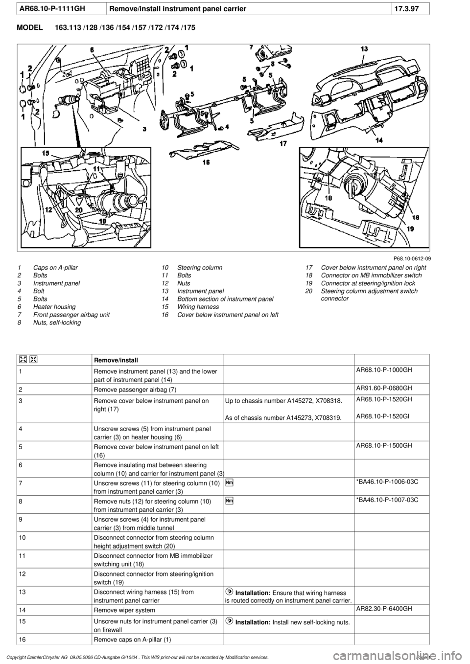
AR68.10-P-1111GH
Remove/install instrument panel carrier
17.3.97
MODEL
163.113 /128 /136 /154 /157 /172 /174 /175
P68.10-0612-09
1
Caps on A-pillar
2
Bolts
3
Instrument panel
4
Bolt
5
Bolts
6
Heater housing
7
Front passenger airbag unit
8
Nuts, self-locking
17
Cover below instrument panel on right
18
Connector on MB immobilizer switch
19
Connector at steering/ignition lock
20
Steering column adjustment switch
connector
10
Steering column
11
Bolts
12
Nuts
13
Instrument panel
14
Bottom section of instrument panel
15
Wiring harness
16
Cover below instrument panel on left
Remove/install
1
Remove instrument panel (13) and the lower
part of instrument panel (14)
AR68.10-P-1000GH
2
Remove passenger airbag (7)
AR91.60-P-0680GH
3
Remove cover below instrument panel on
right (17)
Up to chassis number A145272, X708318.
AR68.10-P-1520GH
As of chassis number A145273, X708319.
AR68.10-P-1520GI
4
Unscrew screws (5) from instrument panel
carrier (3) on heater housing (6)
5
Remove cover below instrument panel on left
(16)
AR68.10-P-1500GH
6
Remove insulating mat between steering
column (10) and carrier for instrument panel (3)
7
Unscrew screws (11) for steering column (10)
from instrument panel carrier (3)
*BA46.10-P-1006-03C
8
Remove nuts (12) for steering column (10)
from instrument panel carrier (3)
*BA46.10-P-1007-03C
9
Unscrew screws (4) for instrument panel
carrier (3) from middle tunnel
10
Disconnect connector from steering column
height adjustment switch (20)
11
Disconnect connector from MB immobilizer
switching unit (18)
12
Disconnect connector from steering/ignition
switch (19)
13
Disconnect wiring harness (15) from
instrument panel carrier
Installation:
Ensure that wiring harness
is routed correctly on instrument panel carrier.
14
Remove wiper system
AR82.30-P-6400GH
15
Unscrew nuts for instrument panel carrier (3)
on firewall
Installation:
Install new self-locking nuts.
16
Remove caps on A-pillar (1)
Copyright DaimlerChrysler AG 09.05.2006 CD-Ausgabe G/10/04 . This WIS print-out will not be recorde
d by Modification services.
Page 1
Page 3528 of 4133

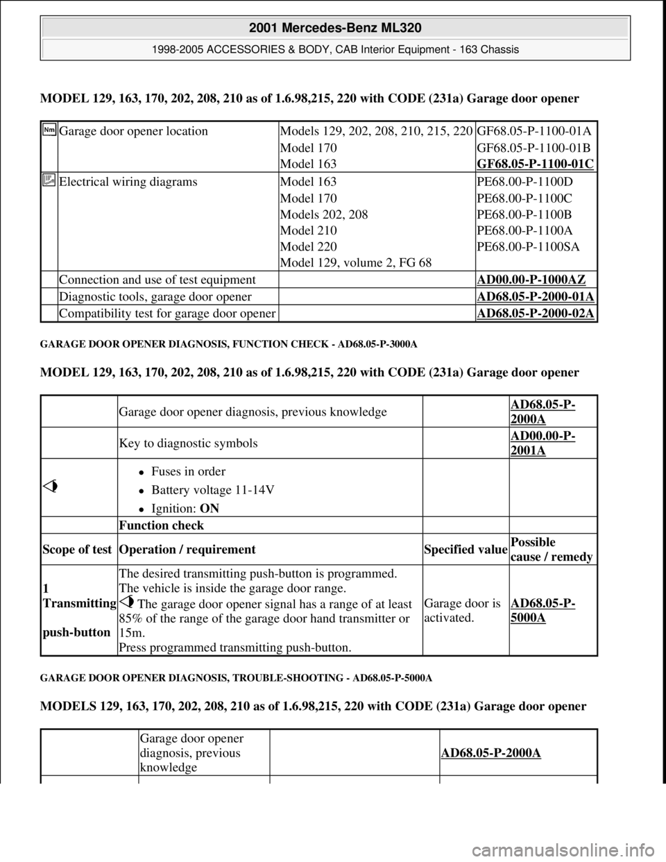
MODEL 129, 163, 170, 202, 208, 210 as of 1.6.98,215, 220 with CODE (231a) Garage door opener
GARAGE DOOR OPENER DIAGNOSIS, FUNCTION CHECK - AD68.05-P-3000A
MODEL 129, 163, 170, 202, 208, 210 as of 1.6.98,215, 220 with CODE (231a) Garage door opener
GARAGE DOOR OPENER DIAGNOSIS, TROUBLE-SHOOTING - AD68.05-P-5000A
MODELS 129, 163, 170, 202, 208, 210 as of 1.6.98,215, 220 with CODE (231a) Garage door opener
Garage door opener locationModels 129, 202, 208, 210, 215, 220GF68.05-P-1100-01A
Model 170GF68.05-P-1100-01B
Model 163GF68.05-P-1100-01C
Electrical wiring diagramsModel 163PE68.00-P-1100D
Model 170PE68.00-P-1100C
Models 202, 208PE68.00-P-1100B
Model 210PE68.00-P-1100A
Model 220PE68.00-P-1100SA
Model 129, volume 2, FG 68
Connection and use of test equipment AD00.00-P-1000AZ
Diagnostic tools, garage door opener AD68.05-P-2000-01A
Compatibility test for garage door opener AD68.05-P-2000-02A
Garage door opener diagnosis, previous knowledge AD68.05-P-
2000A
Key to diagnostic symbols AD00.00-P-
2001A
Fuses in order
Battery voltage 11-14V
Ignition: ON
Function check
Scope of test Operation / requirement Specified value Possible
cause / remedy
1
Transmitting
push-button
The desired transmitting push-button is programmed.
The vehicle is inside the garage door range.
The garage door opener signal has a range of at least
85% of the range of the garage door hand transmitter or
15m.
Press programmed transmitting push-button.
Garage door is
activated.AD68.05-P-
5000A
Garage door opener
diagnosis, previous
knowledge
AD68.05-P-2000A
2001 Mercedes-Benz ML320
1998-2005 ACCESSORIES & BODY, CAB Interior Equipment - 163 Chassis
me
Saturday, October 02, 2010 3:35:21 PMPage 10 © 2006 Mitchell Repair Information Company, LLC.
Page 3529 of 4133

Fuses in order.
Battery voltage
11-14 V
Ignition: ON
Troubleshooting
Complaint Possible cause Note Remedy
The garage door
cannot be
activated with the
garage door
opener installed
in the vehicle.
The garage door opener
has not been
programmed correctly.
GF68.05-P-0001A
The garage door is
defective
Check garage door: Activate
the garage door with the
hand transmitter. If the
garage door cannot be
opened and closed with the
hand transmitter, the garage
door has a mechanical or
electrical defect.
The garage door's
receiver and the garage
door opener installed in
the vehicle are not
compatible.
A list of compatible garage
doors is included in the
passenger car sales manualIf the used garage door is not
listed check compatibility
with compatibility tester.
Compatibility check of
electrical system for garage
door opener Models 129, 170,
202, 208, 210 as of 1.6.98, 163
as of 1.9.01, 215, 220 with
CODE (231a) garage door
opener Compatibility check for
garage door opener.
AD68.05-P-6000-02A
AD68.05
-P-2000-02A
Voltage supply to
garage door opener
interrupted.Model 208 as of 1.6.98, except
CODE (249a)
Automatic dimming inside
rearview mirror
AD68.05-P-6000-01A
Model 202 as of 1.6.98, Model
210 as of 1.6.98, except CODE
(249a)
Automatic dimming inside
rearview mirror
AD68.05-P-6000-01C
Model 202 as of 1.6.98, Model
208 as of 1.6.98, Model 210 as
of 1.6.98, with CODE (249a) AD68.05-P-6000-01G
2001 Mercedes-Benz ML320
1998-2005 ACCESSORIES & BODY, CAB Interior Equipment - 163 Chassis
me
Saturday, October 02, 2010 3:35:21 PMPage 11 © 2006 Mitchell Repair Information Company, LLC.