1997 MERCEDES-BENZ ML430 ignition
[x] Cancel search: ignitionPage 3844 of 4133
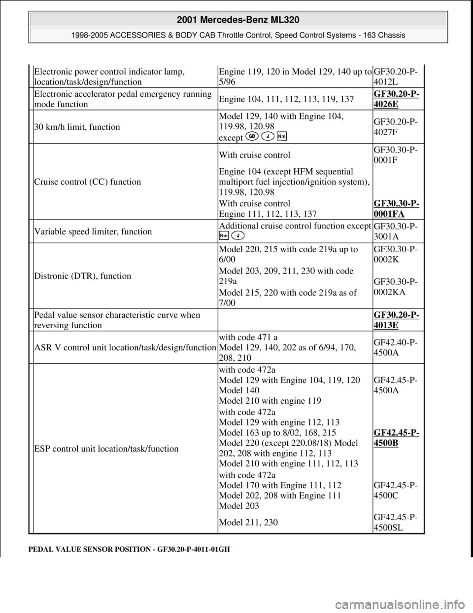
PEDAL VALUE SENSOR PO SITION - GF30.20-P-4011-01GH
Electronic power control indicator lamp,
location/task/design/functionEngine 119, 120 in Model 129, 140 up to
5/96GF30.20-P-
4012L
Electronic accelerator pe dal emergency running
mode functionEngine 104, 111, 112, 113, 119, 137GF30.20-P-
4026E
30 km/h limit, function
Model 129, 140 with Engine 104,
119.98, 120.98
except GF30.20-P-
4027F
Cruise control (CC) function
With cruise controlGF30.30-P-
0001F
Engine 104 (except HFM sequential
multiport fuel injection/ignition system),
119.98, 120.98
With cruise control
Engine 111, 112, 113, 137GF30.30-P-
0001FA
Variable speed limiter, functionAdditional cruise control function except
GF30.30-P-
3001A
Distronic (DTR), function
Model 220, 215 with code 219a up to
6/00GF30.30-P-
0002K
Model 203, 209, 211, 230 with code
219a
GF30.30-P-
0002KA
Model 215, 220 with code 219a as of
7/00
Pedal value sensor characteristic curve when
reversing function GF30.20-P-
4013E
ASR V control unit location/task/design/function
with code 471 a
Model 129, 140, 202 as of 6/94, 170,
208, 210GF42.40-P-
4500A
ESP control unit location/task/function
with code 472a
Model 129 with Engine 104, 119, 120
Model 140
Model 210 with engine 119
GF42.45-P-
4500A
with code 472a
Model 129 with engine 112, 113
Model 163 up to 8/02, 168, 215
Model 220 (except 220.08/18) Model
202, 208 with engine 112, 113
Model 210 with engine 111, 112, 113
GF42.45-P-
4500B
with code 472a
Model 170 with Engine 111, 112
Model 202, 208 with Engine 111
Model 203
GF42.45-P-
4500C
Model 211, 230GF42.45-P-
4500SL
2001 Mercedes-Benz ML320
1998-2005 ACCESSORIES & BODY CAB Throttle Control, Speed Control Systems - 163 Chassis
me
Saturday, October 02, 2010 3:36:27 PMPage 4 © 2006 Mitchell Repair Information Company, LLC.
Page 3857 of 4133
different engine loads, e.g. power steering turned to full lock, engaging drive mode, switching on AC
compressor
different mixture, e.g. from activated charcoal canister if purging activated (depending on activated
charcoal charge)
Function
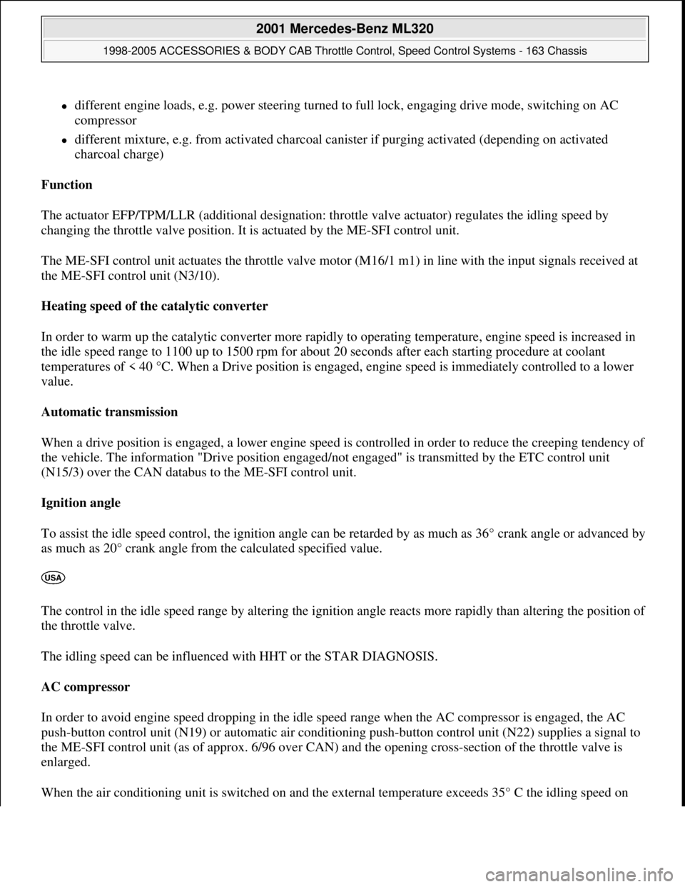
The actuator EFP/TPM/LLR (additional designation: throttle valve actuator) regulates the idling speed by
changing the throttle valve position. It is actuated by the ME-SFI control unit.
The ME-SFI control unit actuates the throttle valve motor (M16/1 m1) in line with the input signals received at
the ME-SFI control unit (N3/10).
Heating speed of the catalytic converter
In order to warm up the catalytic converter more rapidly to operating temperature, engine speed is increased in
the idle speed range to 1100 up to 1500 rpm for about 20 seconds after each starting procedure at coolant
temperatures of < 40 °C. When a Drive position is engaged, engine speed is immediately controlled to a lower
value.
Automatic transmission
When a drive position is engaged, a lower engine speed is controlled in order to reduce the creeping tendency o
f
the vehicle. The information "Drive position engaged/not engaged" is transmitted by the ETC control unit
(N15/3) over the CAN databus to the ME-SFI control unit.
Ignition angle
To assist the idle speed control, the ignition angle can be retarded by as much as 36° crank angle or advanced by
as much as 20° crank angle from the calculated specified value.
The control in the idle speed range by altering the ignition angle reacts more rapidly than altering the position o
f
the throttle valve.
The idling speed can be influenced with HHT or the STAR DIAGNOSIS.
AC compressor
In order to avoid engine speed dropping in the idle speed range when the AC compressor is engaged, the AC
push-button control unit (N19) or automatic air conditioning push-button control unit (N22) supplies a signal to
the ME-SFI control unit (as of approx. 6/96 over CAN) and the opening cross-section of the throttle valve is
enlarged.
When the air conditionin
g unit is switched on and the external temperature exceeds 35° C the idling speed on
2001 Mercedes-Benz ML320
1998-2005 ACCESSORIES & BODY CAB Throttle Control, Speed Control Systems - 163 Chassis
me
Saturday, October 02, 2010 3:36:27 PMPage 17 © 2006 Mitchell Repair Information Company, LLC.
Page 3858 of 4133
vehicles delivered from 6/00 is increased for the driving mode selected by about 100 rpm when the switch-on
threshold of about 900 rpm is exceeded. This increase is cancelled again when the external temperature drops
below 32° C.
Undervoltage
If the engine control unit detects an undervoltage the idling speed is increased until the ignition is switched off
for the driving mode selected by about 100 rpm.
If the control unit SBC reports an undervoltage to the engine control unit over CAN the idling speed for the
driving mode selected is increased to about 750 rpm.
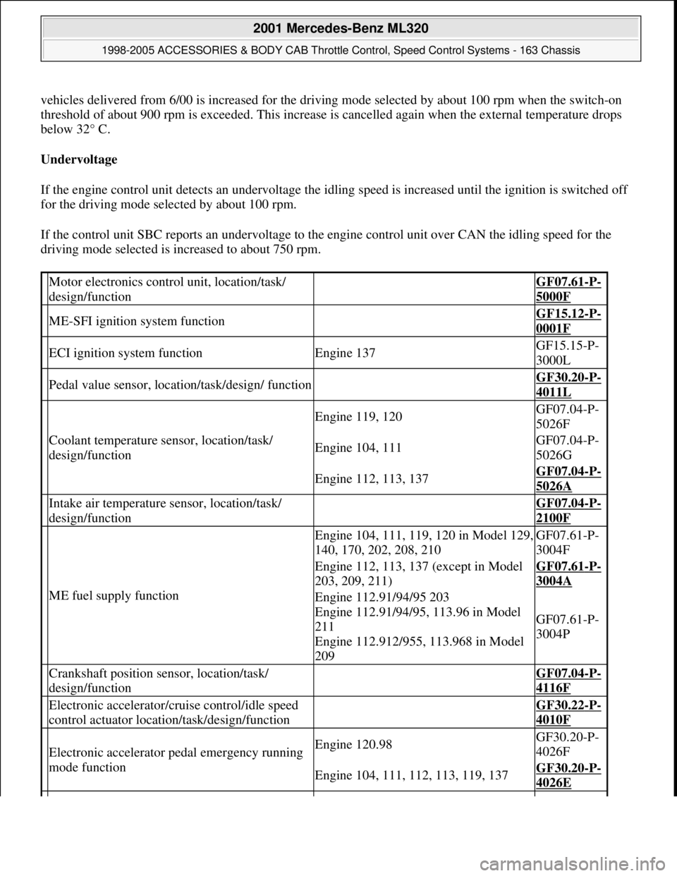
Motor electronics control unit, location/task/
design/function GF07.61-P-
5000F
ME-SFI ignition system function GF15.12-P-
0001F
ECI ignition system functionEngine 137GF15.15-P-
3000L
Pedal value sensor, location/task/design/ function GF30.20-P-
4011L
Coolant temperature sensor, location/task/
design/function
Engine 119, 120GF07.04-P-
5026F
Engine 104, 111GF07.04-P-
5026G
Engine 112, 113, 137GF07.04-P-
5026A
Intake air temperature sensor, location/task/
design/function GF07.04-P-
2100F
ME fuel supply function
Engine 104, 111, 119, 120 in Model 129,
140, 170, 202, 208, 210GF07.61-P-
3004F
Engine 112, 113, 137 (except in Model
203, 209, 211)GF07.61-P-
3004A
Engine 112.91/94/95 203
Engine 112.91/94/95, 113.96 in Model
211
Engine 112.912/955, 113.968 in Model
209
GF07.61-P-
3004P
Crankshaft position sensor, location/task/
design/function GF07.04-P-
4116F
Electronic accelerator/cruise control/idle speed
control actuator location/task/design/function GF30.22-P-
4010F
Electronic accelerator pedal emergency running
mode functionEngine 120.98GF30.20-P-
4026F
Engine 104, 111, 112, 113, 119, 137GF30.20-P-
4026E
2001 Mercedes-Benz ML320
1998-2005 ACCESSORIES & BODY CAB Throttle Control, Speed Control Systems - 163 Chassis
me
Saturday, October 02, 2010 3:36:27 PMPage 18 © 2006 Mitchell Repair Information Company, LLC.
Page 3861 of 4133
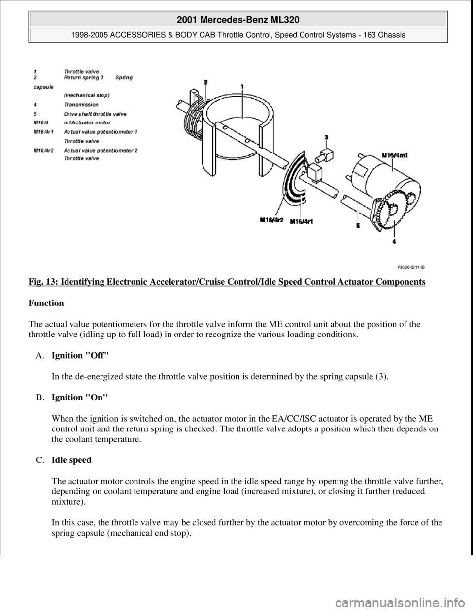
Fig. 13: Identifying Electronic Accelerator/Cruise Control/Idle Speed Control Actuator Components
Function
The actual value potentiometers for the throttle valve inform the ME control unit about the position of the
throttle valve (idling up to full load) in order to recognize the various loading conditions.
A.Ignition "Off"
In the de-energized state the throttle valve position is determined by the spring capsule (3).
B.Ignition "On"
When the ignition is switched on, the actuator motor in the EA/CC/ISC actuator is operated by the ME
control unit and the return spring is checked. The throttle valve adopts a position which then depends on
the coolant temperature.
C.Idle speed
The actuator motor controls the engine speed in the idle speed range by opening the throttle valve further,
depending on coolant temperature and engine load (increased mixture), or closing it further (reduced
mixture).
In this case, the throttle valve may be closed further by the actuator motor by overcoming the force of the
sprin
g capsule (mechanical end stop).
2001 Mercedes-Benz ML320
1998-2005 ACCESSORIES & BODY CAB Throttle Control, Speed Control Systems - 163 Chassis
me
Saturday, October 02, 2010 3:36:27 PMPage 21 © 2006 Mitchell Repair Information Company, LLC.
Page 3881 of 4133
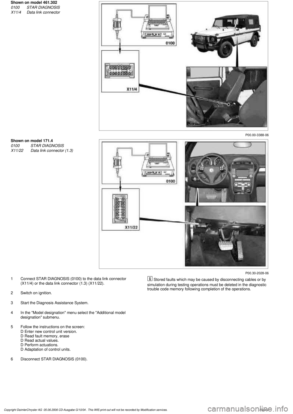
P00.00-3388-06
Shown on model 461.302
0100
STAR DIAGNOSIS
X11/4
Data link connector
P00.30-2028-06
Shown on model 171.4
0100
STAR DIAGNOSIS
X11/22
Data link connector (1.3)
1
Connect STAR DIAGNOSIS (0100) to the data link connector
(X11/4) or the data link connector (1.3) (X11/22).
2
Switch on ignition.
3
Start the Diagnosis Assistance System.
4
In the "Model designation" menu select the "Additional model
designation" submenu.
5
Follow the instructions on the screen:
D
Enter new control unit version.
D
Read fault memory, erase
D
Read actual values.
D
Perform actuations.
D
Adaptation of control units.
6
Disconnect STAR DIAGNOSIS (0100).
Stored faults which may be caused by disconnecting cables or by
simulation during testing operations must be deleted in the diagnostic
trouble code memory following completion of the operations.
Copyright DaimlerChrysler AG 05.06.2006 CD-Ausgabe G/10/04 . This WIS print-out will not be recorde
d by Modification services.
Page 2
Page 3883 of 4133
2001-04 STARTING & CHARGING SYSTEMS Starters - 163 Chassis
MODEL IDENTIFICATION
MODEL IDENTIFICATION
DESCRIPTION
Starter is a brush-type, series-wound el ectric motor with an overrunning clutch. Field frame contains field coils
and is enclosed by commutator/drive bushing end frame, which carries pole shoes. A splined armature shaft
carries drive assembly.
TROUBLE SHOOTING
BASIC TROUBLESHOOTING
If starter is noisy, the cause could be bent or damaged gear tooth chamfers on ring gear. This cannot be seen
with starter installed in ve hicle. Activate starter without switching ignition on. Me tallic noise should not be
heard. If noise is he ard, replace ring gear.
PRELIMINARY INSPECTION
Verify customer complaint by operating system. Visually inspect for obvious signs of mechanical and electrical
damage. Check generator belt tension and condition. Ensure that battery voltage is within specifications. Inspect
for blown fuses and damaged relays. For fuse and/or relay identification, see WIRING DIAGRAMS
.
WARNING:
Vehicles are equipped with air bag supplemental restraint system. Before
attempting any repairs involving steer ing column, instrument panel or
related components, see SERVICE PRECAUTIONS (or AIR BAG SAFETY
PRECAUTIONS) and DISABLING & ACTIVATING AIR BAG SYSTEM in
appropriate AIR BAG REST RAINT SYSTEMS article.
NOTE: When the battery is di sconnected, vehicle computer and memory system may
lose data. Driveability problems may exist until computer systems have
completed a relearn cycle. Radio will not operate until coded. Obtain code card
from customer.
NOTE: The following table identifies mo dels applicable to this article.
ModelChassisEngine Number
ML430 (2001)163.172113.942
ML320 (2001-03)163.154112.942
ML55 AMG (2001-03)163.174113.981
ML500 (2002-04)163.175113.965
ML350 (2003-04)163.157112.970
2001 Mercedes-Benz ML320
2001-04 STARTING & CHARGING SYSTEMS Starters - 163 Chassis
2001 Mercedes-Benz ML320
2001-04 STARTING & CHARGING SYSTEMS Starters - 163 Chassis
me
Saturday, October 02, 2010 3:19:47 PMPage 1 © 2006 Mitchell Repair Information Company, LLC.
me
Saturday, October 02, 2010 3:19:50 PMPage 1 © 2006 Mitchell Repair Information Company, LLC.
Page 3884 of 4133
Verify ground connection integrity between engine, body, battery and generator. Check for damaged wiring
harnesses and/or switches. Check fo r a broken or partially broken wire inside insulation, which could cause
system malfunction but prove good in a continuity/vol tage check with system disconnected. Ensure any
aftermarket electronic e quipment is properly installed. If fault is found, repair as necessary. If no fault is found,
check for conditions that might cause an intermittent situation.
SERVICE PRECAUTIONS
BATTERY DISCONNECT/CONNECT
Disconnect/Connect Procedures
1. Turn ignition off. Open engine hood. After opening ve hicle wait at least 4 minutes before disconnecting
battery or alarm wi ll be triggered.
2. Disconnect negative battery cable (1) and insulate cable lug to prevent unwanted contact with ground
point (W16/4). See Fig. 1
.
3. To connect, reverse disconnect procedur e. Tighten nut (5) to specification. See TORQUE
SPECIFICATIONS .
4. Perform basic programming, read Diagnostic Tr ouble Code (DTC) memory and erase DTCs from
memory. See BASIC PROGRAMMING
and RETRIEVING & ERASING DIAGNOSTIC
TROUBLE CODES .
NOTE: Numbers and letters in text refe
r to numbers and letters in figures.
2001 Mercedes-Benz ML320
2001-04 STARTING & CHARGING SYSTEMS Starters - 163 Chassis
me
Saturday, October 02, 2010 3:19:47 PMPage 2 © 2006 Mitchell Repair Information Company, LLC.
Page 3886 of 4133
switch pressed for 5 to 10 seconds.
6. Normalize power windows. Completely close each wi ndow with manual switch. Hold switch in closed
position for 5 seconds.
Coding radio
Hi-Line Premium With Bose(R)
1. Turn ignition on. CODE will appear on radio displa y. Enter first code number with station button. For
example, station button 1 is number 1.
2. After entering first number, CODE will disappear and first number entered will appear followed by 4
dashes. The next character to be entered flashes. Repeat procedure until all numbers are entered.
3. If an input error has occurred it can be corrected at this time by reentering the complete correct code.
4. Confirm entry of correct code with < or > button.
5. If an incorrect code number has been entered, CODE appears again on display. If an incorrect code is
entered 3 times, WAIT appears on display and ra dio locks up for approximately 10 minutes. If an
incorrect code is entered 3 times again, lock time increases to 60 mi nutes. Radio must remain switched on
during lock up time.
MB
1. Turn ignition on. CODE will appear on radio displa y. Enter first code number with station button. For
example, station button 1 is number 1.
2. After entering first number, CODE will disappear and first number entered will appear followed by 4
dashes. The next character to be entered flashes.
3. After entering all 5 numbers the first character starts flashing again. If an input error has occurred it can
be corrected at this time by reentering the complete correct code.
4. Press TUNE, AUTO/SEEK or SC butt on. If code is correct, radio automatically switches on and indicates
the station or frequency stored wi th station button 1. If an incorrect code number has been entered, CODE
appears again on display. If an inco rrect code is entered 3 times, WAIT appears on display and radio
locks up for approximately 10 minutes. If an incorrect code is entered 3 times again, radio locks up for
approximately 10 additional minutes. After 9 incorrec t attempts, lock time increases to 60 minutes.
Another 3 incorrect entries locks up radio for anothe r 60 minutes. Radio must remain switched on during
lock up time.
RETRIEVING & ER ASING DIAGNOSTIC TROUBLE CODES
RETRIEVING DIAGNOSTIC TROUBLE CODES
NOTE: Before replacing any component that scan tool suggests are faulty, ensure that
all wiring connections and harness connect ors are okay. Ensure that power and
ground circuits are functioning properl y. For circuit identification, see
appropriate WIRING DIAGRAM unde r ENGINE PERFORMANCE in SYSTEM
WIRING DIAGRAMS for vehicle being tested.
2001 Mercedes-Benz ML320
2001-04 STARTING & CHARGING SYSTEMS Starters - 163 Chassis
me
Saturday, October 02, 2010 3:19:47 PMPage 4 © 2006 Mitchell Repair Information Company, LLC.