1997 MERCEDES-BENZ ML430 ignition
[x] Cancel search: ignitionPage 3542 of 4133
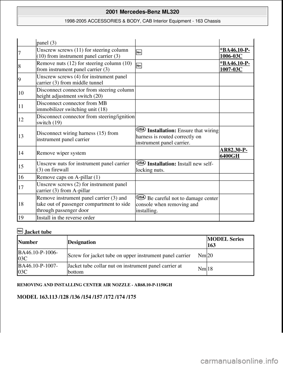
Jacket tube
REMOVING AND INSTALLING CENTER AIR NOZZLE - AR68.10-P-1150GH
MODEL 163.113 /128 /136 /154 /157 /172 /174 /175
panel (3)
7Unscrew screws (11) for steering column
(10) from instrument panel carrier (3) *BA46.10-P-
1006-03C
8Remove nuts (12) for steering column (10)
from instrument panel carrier (3) *BA46.10-P-
1007-03C
9Unscrew screws (4) for instrument panel
carrier (3) from middle tunnel
10Disconnect connector from steering column
height adjustment switch (20)
11Disconnect connector from MB
immobilizer switching unit (18)
12Disconnect connector from steering/ignition
switch (19)
13Disconnect wiring harness (15) from
instrument panel carrier Installation:Ensure that wiring
harness is routed correctly on
instrument panel carrier.
14Remove wiper system AR82.30-P-
6400GH
15Unscrew nuts for instrument panel carrier
(3) on firewall Installation: Install new self-
locking nuts.
16Remove caps on A-pillar (1)
17Unscrew screws (2) for instrument panel
carrier (3) from A-pillar
18
Remove instrument panel carrier (3) and
take out of passenger compartment to side
through passenger doorBe careful not to damage center
console when removing and
installing.
19Install in the reverse order
NumberDesignationMODEL Series
163
BA46.10-P-1006-
03CScrew for jacket tube on upper instrument panel carrierNm20
BA46.10-P-1007-
03CJacket tube collar nut on instrument panel carrier at
bottomNm18
2001 Mercedes-Benz ML320
1998-2005 ACCESSORIES & BODY, CAB Interior Equipment - 163 Chassis
me
Saturday, October 02, 2010 3:35:21 PMPage 24 © 2006 Mitchell Repair Information Company, LLC.
Page 3715 of 4133
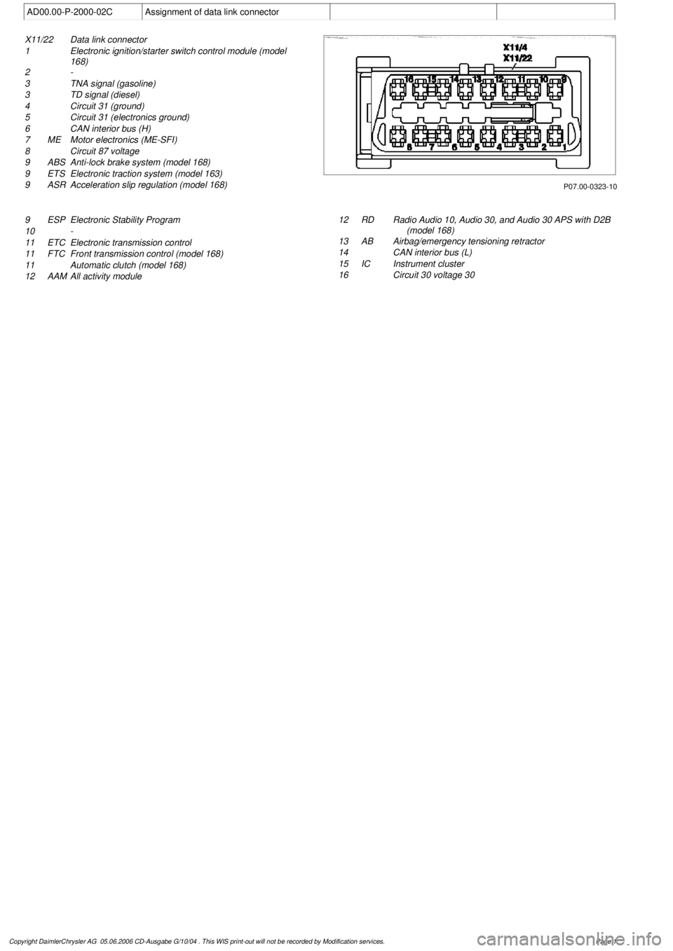
AD00.00-P-2000-02C
Assignment of data link connector
P07.00-0323-10
X11/22
Data link connector
1
Electronic ignition/starter switch control module (model
168)
2 -
3
TNA signal (gasoline)
3
TD signal (diesel)
4
Circuit 31 (ground)
5
Circuit 31 (electronics ground)
6
CAN interior bus (H)
7
ME
Motor electronics (ME-SFI)
8
Circuit 87 voltage
9
ABS
Anti-lock brake system (model 168)
9
ETS
Electronic traction system (model 163)
9
ASR
Acceleration slip regulation (model 168)
9
ESP
Electronic Stability Program
10
-
11 ETC
Electronic transmission control
11
FTC
Front transmission control (model 168)
11
Automatic clutch (model 168)
12
AAM
All activity module
12
RD
Radio Audio 10, Audio 30, and Audio 30 APS with D2B
(model 168)
13
AB
Airbag/emergency tensioning retractor
14
CAN interior bus (L)
15 IC
Instrument cluster
16
Circuit 30 voltage 30
Copyright DaimlerChrysler AG 05.06.2006 CD-Ausgabe G/10/04 . This WIS print-out will not be recorde
d by Modification services.
Page 1
Page 3734 of 4133

GF54.30-P-4104A
Outside temperature display, location/function
8.7.99
MODEL
129
MODEL
140 as of 1.6.96
MODEL
170
MODEL
163, 202 with CODE (240a) Outside temperature display
MODEL
202 as of 1.8.96
MODEL
168
MODEL
208 up to 31.7.99,
210 as of 1.6.96 up to 30.6.99
To display the temperature, the
outside temperature indicator
A1p4
requires:
D
the outside temperature
D
the speed signal
D
the engine running time
and
D
the coolant temperature (model 129, and model 140 as of
1.6.96, model 170, model 202 as of 08/96 and model 163,
model 168, model 210)
The outside temperature is determined by the outside temperature
indicator temperature sensor B14. The temperature sensor is
installed at the front left of the vehicle under the bumper and
connected to the instrument cluster A1 via the 21 or 25-pin
connector, coding part A terminal 1 and 2.
The speed signal, engine running time and engine temperature are
determined internally by the instrument cluster A1.
Since the outside temperature display depends on the speed, engine
running time and coolant temperature, high temperatures (influenced
by the heat generated by the engine, for example) are not displayed
when the vehicle is stationary or moving slowly.
Function, model 202 until 08/95
When the ignition is switched on and off and at speeds below approx.
20 km/h, the last temperature measured is stored and displayed.
If the measured outside temperature drops below the stored value,
the current measured temperature is displayed.
If the outside temperature rises above the stored value, the current
measured outside temperature is displayed only after the following
delays:
D
When the engine is not running, the current outside
temperature is only displayed after 6 times the engine running
time. For example, if the preceding running time was 5 minutes,
the current temperature is not displayed until after 30 minutes.
The maximum delay, however, is 1 hour.
Up to 09.94
D
At vehicle speeds between 20-60 km/h, outside temperatures
are displayed after a delay of approx. 5 min.
D
At vehicle speeds over 60 km/h, outside temperatures are
displayed after a delay of approx. 2 minutes.
As of 09.94
D
At vehicle speeds between 20-45 km/h, outside temperatures
are displayed after a delay of approx. 3 min.
D
At vehicle speeds over 45 km/h, outside temperatures are
displayed after a delay of approx. 1.5 min.
Function
Model 129, model 140 as of 1.6.96, model 170, model 202 as of
08/96, model 163, model 168, model 208 and model 210
D
When the ignition is turned on or off
and with an engine temperature < 60°C
the current temperature is always stored and displayed.
D
When the ignition is turned off
and with an engine temperature < 60°C
the temperature last measured is stored and displayed.
D
When the ignition is turned on
and when an engine temperature < 60(C
The stored temperature is displayed.
If the measured outside temperature drops below the stored value,
the current measured temperature is displayed.
If the outside temperature rises above the stored value, the current
measured outside temperature is displayed only after the following
delays:
D
When the engine is not running, the current outside
temperature is only displayed after 6 times the engine running
time. For example, if the preceding running time was 5 minutes,
the current temperature is not displayed until after 30 minutes.
The maximum delay, however, is 1 hour.
D
At vehicle speeds between 20-45 km/h, outside temperatures
are displayed after a delay of approx. 3 minutes.
D
At vehicle speeds above 45 km/h, outside temperatures are
displayed after a delay of approx. 1.5 minutes.
Copyright DaimlerChrysler AG 05.06.2006 CD-Ausgabe G/10/04 . This WIS print-out will not be recorde
d by Modification services.
Page 1
Page 3775 of 4133
AP15.10-P-1580GHReplace spark plugs
1.7.97
ENGINE
112.942 in MODEL 163.154
ENGINE
112.970 in MODEL 163.157
ENGINE
113.942 in MODEL 163.172
ENGINE
113.981 in MODEL 163.174
ENGINE
113.965 in MODEL 163.175
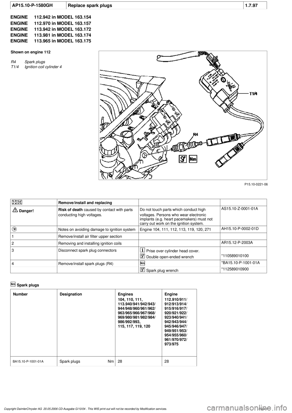
P15.10-0221-06
Shown on engine 112
R4
Spark plugs
T1/4
Ignition coil cylinder 4
Remove/install and replacing
Danger!
Risk of death
caused by contact with parts
conducting high voltages.
Do not touch parts which conduct high
voltages. Persons who wear electronic
implants (e.g. heart pacemakers) must not
carry out work on the ignition system.
AS15.10-Z-0001-01A
Notes on avoiding damage to ignition system
Engine 104, 111, 112, 113, 119, 120, 271
AH15.10-P-0002-01D
1
Remove/install air filter upper section
2
Removing and installing ignition coils
AR15.12-P-2003A
3
Disconnect spark plug connectors
Prise over cylinder head cover.
Double open-ended wrench
*110589010100
4
Remove/install spark plugs (R4)
*BA15.10-P-1001-01A
Spark plug wrench
*112589010900
Spark plugs
Number
Designation
Engines
104, 110, 111,
113.940/941/942/943/
944/948/960/961/962/
963/965/966/967/968/
969/980/981/982/984/
986/992/993,
115, 117, 119, 120
Engine
112.910/911/
912/913/914/
915/916/917/
920/921/922/
923/940/941/
942/943/944/
945/946/947/
949/951/953/
954/955/960/
961/970/972/
973/975
BA15.10-P-1001-01A
Spark plugs
Nm
2828
Copyright DaimlerChrysler AG 20.05.2006 CD-Ausgabe G/10/04 . This WIS print-out will not be recorde
d by Modification services.
Page 1
Page 3798 of 4133
GF91.29-P-0002GH
Electric seat adjustment with memory, function
14.7.99
MODEL
163 as of 1.1.00
with CODE (241) Memory for electrically adjustable left front seat
with CODE (242a) Memory for electrically adjustable right front seat
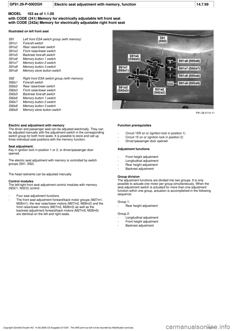
P91.29-2114-11
Illustrated on left front seat
S91
Left front ESA switch group (with memory)
S91s1
Fore/aft switch
S91s2
Rear raise/lower switch
S91s3
Front raise/lower switch
S91s5
Backrest fore/aft switch
S91s6
Memory button 1 switch
S91s7
Memory button 2 switch
S91s8
Memory button 3 switch
S91s9
Memory store button switch
S92
Right front ESA switch group (with memory)
S92s1
Fore/aft switch
S92s2
Rear raise/lower switch
S92s3
Front raise/lower switch
S92s5
Backrest fore/aft switch
S92s6
Memory button 1 switch
S92s7
Memory button 2 switch
S92s8
Memory button 3 switch
S92s9
Memory store button switch
Electric seat adjustment with memory
The driver and passenger seat can be adjusted electrically. They can
be adjusted manually with the adjustment switch in the corresponding
switch group for both front seats. It is possible to store and call up
three individual seat positions with the memory function.
Seat adjustment:
Key in ignition lock in position 1 or 2, or driver/passenger door
opened.
The electric seat adjustment with memory is controlled by switch
groups (S91, S92).
The head restraints can be adjusted manually.
Control modules
The left/right front seat adjustment control modules with memory
(N32/1, N32/2) control:
-
Four seat adjustment functions
-
The front seat adjustment forward/back motor groups (M27m1,
M28m1), the rear raise/lower motors (M27m2, M28m2) and the
front raise/lower motors (M27m3, M28m3) as well as the
backrest adjustment forward/back motors (M27m5, M28m5)
are identical on the left and right seats.
Function prerequisites
-
Circuit 15R on or (ignition lock in position 1)
-
Circuit 15 on or (ignition lock in position 2)
-
Driver/passenger door opened
Adjustment functions
-
Front height adjustment
-
Longitudinal adjustment
-
Rear height adjustment
-
Backrest adjustment
Group division
The adjustment functions are divided into two groups. It is only
possible to actuate one motor per group simultaneously. When the
seat adjustment switch is actuated for more than one adjustment
function within one group, actuation is accomplished in the following
sequence:
Group 1:
-
Rear height adjustment
Group 2:
-
Longitudinal adjustment
-
Front height adjustment
-
Backrest adjustment
Copyright DaimlerChrysler AG 14.06.2006 CD-Ausgabe G/10/04 . This WIS print-out will not be recorde
d by Modification services.
Page 1
Page 3807 of 4133
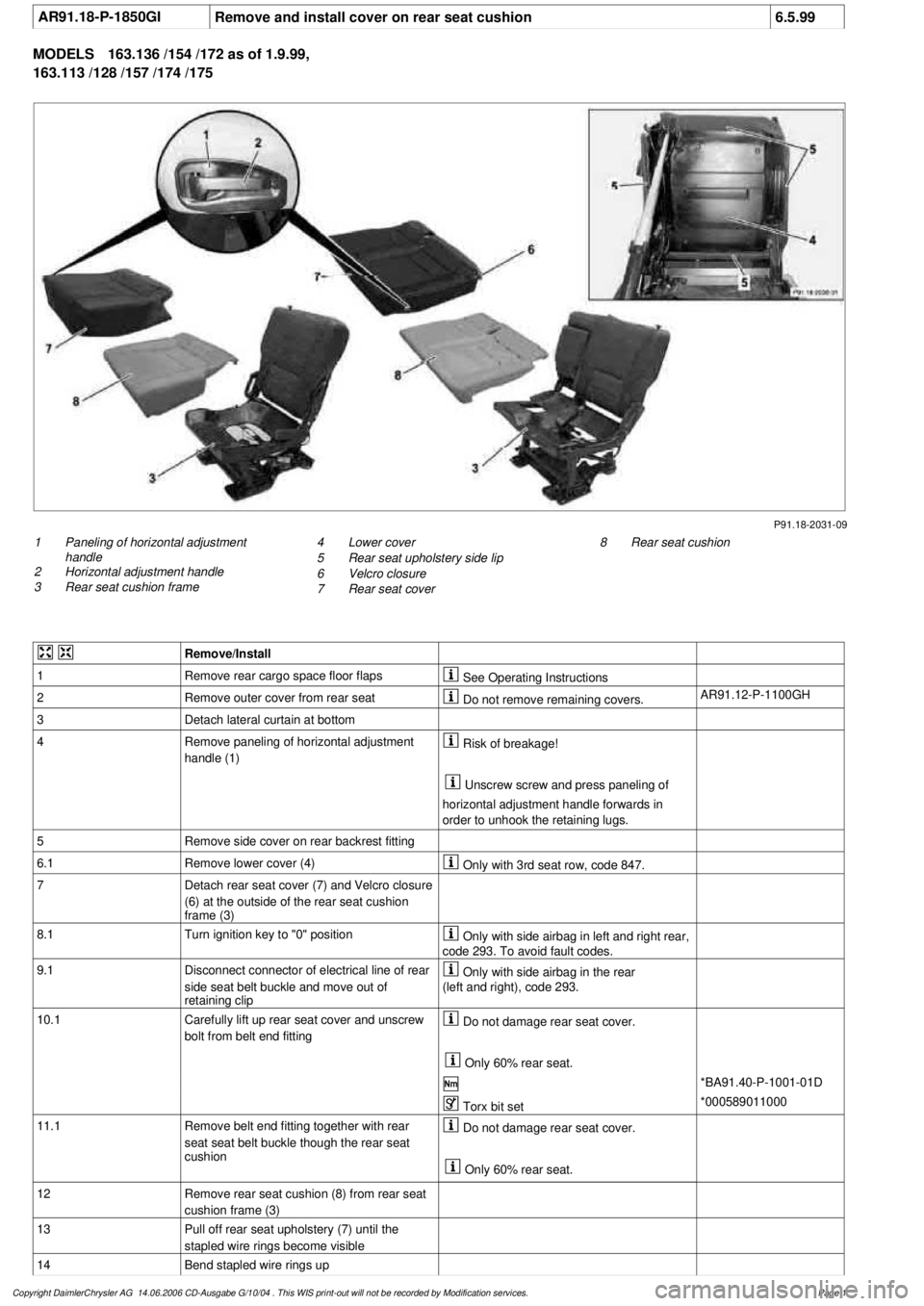
AR91.18-P-1850GI
Remove and install cover on rear seat cushion
6.5.99
MODELS
163.136 /154 /172 as of 1.9.99,
163.113 /128 /157 /174 /175
P91.18-2031-09
1
Paneling of horizontal adjustment
handle
2
Horizontal adjustment handle
3
Rear seat cushion frame
8
Rear seat cushion
4
Lower cover
5
Rear seat upholstery side lip
6
Velcro closure
7
Rear seat cover
Remove/Install
1
Remove rear cargo space floor flaps
See Operating Instructions
2
Remove outer cover from rear seat
Do not remove remaining covers.
AR91.12-P-1100GH
3
Detach lateral curtain at bottom
4
Remove paneling of horizontal adjustment
handle (1)
Risk of breakage!
Unscrew screw and press paneling of
horizontal adjustment handle forwards in
order to unhook the retaining lugs.
5
Remove side cover on rear backrest fitting
6.1
Remove lower cover (4)
Only with 3rd seat row, code 847.
7
Detach rear seat cover (7) and Velcro closure
(6) at the outside of the rear seat cushion
frame (3)
8.1
Turn ignition key to "0" position
Only with side airbag in left and right rear,
code 293. To avoid fault codes.
9.1
Disconnect connector of electrical line of rear
side seat belt buckle and move out of
retaining clip
Only with side airbag in the rear
(left and right), code 293.
10.1
Carefully lift up rear seat cover and unscrew
bolt from belt end fitting
Do not damage rear seat cover.
Only 60% rear seat.
*BA91.40-P-1001-01D
Torx bit set
*000589011000
11.1
Remove belt end fitting together with rear
seat seat belt buckle though the rear seat
cushion
Do not damage rear seat cover.
Only 60% rear seat.
12
Remove rear seat cushion (8) from rear seat
cushion frame (3)
13
Pull off rear seat upholstery (7) until the
stapled wire rings become visible
14
Bend stapled wire rings up
Copyright DaimlerChrysler AG 14.06.2006 CD-Ausgabe G/10/04 . This WIS print-out will not be recorde
d by Modification services.
Page 1
Page 3813 of 4133
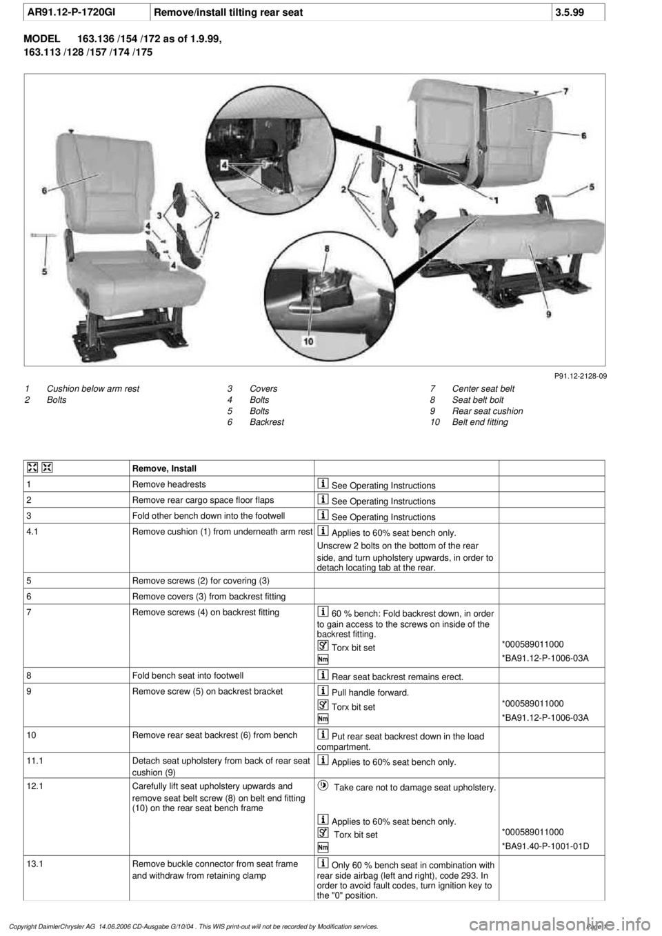
AR91.12-P-1720GI
Remove/install tilting rear seat
3.5.99
MODEL
163.136 /154 /172 as of 1.9.99,
163.113 /128 /157 /174 /175
P91.12-2128-09
1
Cushion below arm rest
2
Bolts
7
Center seat belt
8
Seat belt bolt
9
Rear seat cushion
10
Belt end fitting
3
Covers
4
Bolts
5
Bolts
6
Backrest
Remove, Install
1
Remove headrests
See Operating Instructions
2
Remove rear cargo space floor flaps
See Operating Instructions
3
Fold other bench down into the footwell
See Operating Instructions
4.1
Remove cushion (1) from underneath arm rest
Applies to 60% seat bench only.
Unscrew 2 bolts on the bottom of the rear
side, and turn upholstery upwards, in order to
detach locating tab at the rear.
5
Remove screws (2) for covering (3)
6
Remove covers (3) from backrest fitting
7
Remove screws (4) on backrest fitting
60 % bench: Fold backrest down, in order
to gain access to the screws on inside of the
backrest fitting.
Torx bit set
*000589011000
*BA91.12-P-1006-03A
8
Fold bench seat into footwell
Rear seat backrest remains erect.
9
Remove screw (5) on backrest bracket
Pull handle forward.
Torx bit set
*000589011000
*BA91.12-P-1006-03A
10
Remove rear seat backrest (6) from bench
Put rear seat backrest down in the load
compartment.
11.1
Detach seat upholstery from back of rear seat
cushion (9)
Applies to 60% seat bench only.
12.1
Carefully lift seat upholstery upwards and
remove seat belt screw (8) on belt end fitting
(10) on the rear seat bench frame
Take care not to damage seat upholstery.
Applies to 60% seat bench only.
Torx bit set
*000589011000
*BA91.40-P-1001-01D
13.1
Remove buckle connector from seat frame
and withdraw from retaining clamp
Only 60 % bench seat in combination with
rear side airbag (left and right), code 293. In
order to avoid fault codes, turn ignition key to
the "0" position.
Copyright DaimlerChrysler AG 14.06.2006 CD-Ausgabe G/10/04 . This WIS print-out will not be recorde
d by Modification services.
Page 1
Page 3817 of 4133
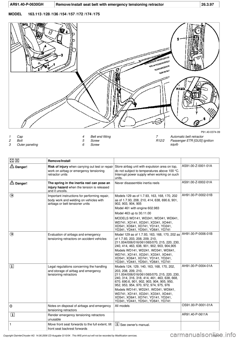
AR91.40-P-0630GH
Remove/install seat belt with emergency tensioning retractor
26.3.97
MODEL
163.113 /128 /136 /154 /157 /172 /174 /175
P91.40-0374-09
1
Cap
2
Bolt
3
Outer paneling
7
Automatic belt retractor
R12/2
Passenger ETR [GUS] ignition
squib
4
Belt end fitting
5
Screw
6
Screw
Remove/Install
Danger!
Risk of injury
when carrying out test or repair
work on airbag or emergency tensioning
retractor units
Store airbag unit with expulsion area on top,
do not subject to temperatures above 100 °C.
Interrupt power supply when working on such
units.
AS91.00-Z-0001-01A
Danger!
The spring in the inertia reel can pose an
injury hazard
when the tension is released
and it uncoils.
Never disassemble inertia reels
AS91.00-Z-0002-01A
Important instructions for performing repair,
body work and welding on vehicles with
airbags or belt tensioner units
Models 129 as of 1.7.93, 163, 168, 170, 202
as of 1.7.93, 208, 210, 414, 638, 690.6, 901,
902, 903, 904, 905
Model 461 with engine 602.983
Model 463 up to 30.11.00
MODELS WD141, WD241, WD341, WD641,
WD741, XD141, XD241, XD341, XD441,
XD541, XD641, XD741, YD141, YD241,
YD341, YD441, YD541, YD641, YD741
AH91.00-P-0002-01B
Evaluation of airbags and emergency
tensioning retractors on accident vehicles
Model 129 as of 1.7.93, 163, 168, 170, 202 as
of 1.7.93, 203, 208, 209, 210,
211.004/006/016/061/065/070, 215, 220, 230,
240, 414, 463, 638, 901, 902, 903, 904,905
Models WD141, WD241, WD341, WD641,
WD741, XD141, XD241, XD341, XD441,
XD541, XD641, XD741, YD141, YD241,
YD341, YD441, YD541, YD641, YD741
AH91.00-P-0006-01B
Legal regulations concerning the handling
and storage of airbag and emergency
tensioning retractors
Models 124, 129, 140, 163, 168, 170, 202,
203, 208, 209, 210,
211.004/006/016/061/065/070, 215, 220, 230,
240, 314, 316, 318, 414, 461, 463, 638, 668,
670, 690.6, 901, 902, 903, 904, 905, 950,
952, 953, 954, 970, 972, 974, 975, 976
Models WD141, WD241, WD341, WD641,
WD741, XD141, XD241, XD341, XD441,
XD541, XD641, XD741, YD141, YD241,
YD341, YD441, YD541, YD641, YD741
AH91.00-P-0004-01A
o
Notes on disposal of airbags and emergency
tensioning retractors
All models
OS91.00-P-0001-01A
Render emergency tensioning retractors
unusable
AR91.40-P-0611A
1
Move front seat forwards to the full extent, tilt
front seat backrest forwards
See owner's manual.
Copyright DaimlerChrysler AG 14.06.2006 CD-Ausgabe G/10/04 . This WIS print-out will not be recorde
d by Modification services.
Page 1