1997 MERCEDES-BENZ ML430 ignition
[x] Cancel search: ignitionPage 2241 of 4133

AF80.57-P-6406A
Engine sometimes fails to start and fault message "Start Error" appear in the
instrument cluster
13.8.04
MODEL
163.136 /154 /172 #A as of 145273,
163.136 /154 /172 #X as of 708319,
163.113 /128 /157 /174 /175
Operation no. of operation texts or standard texts and flat rates
Category
Op. no.
Operation text
Time
Acc. no.
Code
P
541011
Perform quick test
004 WU
------
P
805030
Replace drive authorization system (DAS [FBS]) control unit
(after check)
006 WU
------
Damage code
Cause
Remedy
82 801 90
When the ignition is switched on (circuit
15), the engine control unit sends a start
enable request to the DAS [FBS] control unit.
If during this request circuit 15 is switched off
or interrupted before the DAS [FBS] control
unit could respond, the variable code sent the
first time is used again the next time circuit 15
is switched on, since the original request is
saved by the DAS [FBS] control.
1
Replace the DAS [FBS] control unit.
AR54.21-P-1300GH
The fault message "Start Error" appears
in instrument cluster.
When ordering a new control unit, please
specify the chassis number.
Parts ordering notes
Part no.
Designation
Quantity
163 545 07 16
FBS control unit
1
Copyright DaimlerChrysler AG 05.06.2006 CD-Ausgabe G/10/04 . This WIS print-out will not be recorde
d by Modification services.
Page 1
Page 2249 of 4133
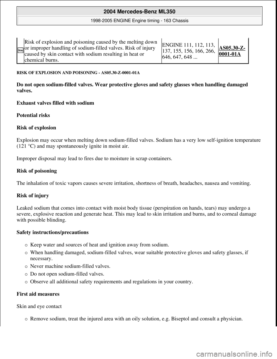
RISK OF EXPLOSION AND PO ISONING - AS05.30-Z-0001-01A
Do not open sodium-filled valves. Wear protectiv e gloves and safety glasses when handling damaged
valves.
Exhaust valves fill ed with sodium
Potential risks
Risk of explosion
Explosion may occur when melting down sodium-filled va lves. Sodium has a very low self-ignition temperature
(121 °C) and may spontaneously ignite in moist air.
Improper disposal may lead to fires due to moisture in scrap containers.
Risk of poisoning
The inhalation of toxic vapors causes severe irritation, shortness of breath, headaches, nausea and vomiting.
Risk of injury
Leaked sodium that comes into contact with moist body tissue (perspiration on hands, tears) may undergo a
severe, explosive reaction and generate heat. This may lead to skin ir ritation and burns, and to corneal damage
with possible blinding.
Safety instructions/precautions
Keep water and sources of heat and ignition away from sodium.
When handling damaged, sodium-filled valves, wear su itable protective gloves and safety glasses, if
necessary.
Never machine sodium-filled valves.
Do not open sodium-filled valves.
Observe all additional safety requireme nts and regulations in your country.
First aid measures
Skin and eye contact
Remove sodium, treat the injured area with an oily solution, e.g. Biseptol and consult a physician.
Risk of explosion and poisoning caused by the melting down
or improper handling of sodium-f illed valves. Risk of injury
caused by skin contact with s odium resulting in heat or
chemical burns.ENGINE 111, 112, 113,
137, 155, 156, 166, 266,
646, 647, 648 ...AS05.30-Z-
0001-01A
2004 Mercedes-Benz ML350
1998-2005 ENGINE Engine timing - 163 Chassis
me
Saturday, October 02, 2010 3:39:37 PMPage 8 © 2006 Mitchell Repair Information Company, LLC.
Page 2251 of 4133
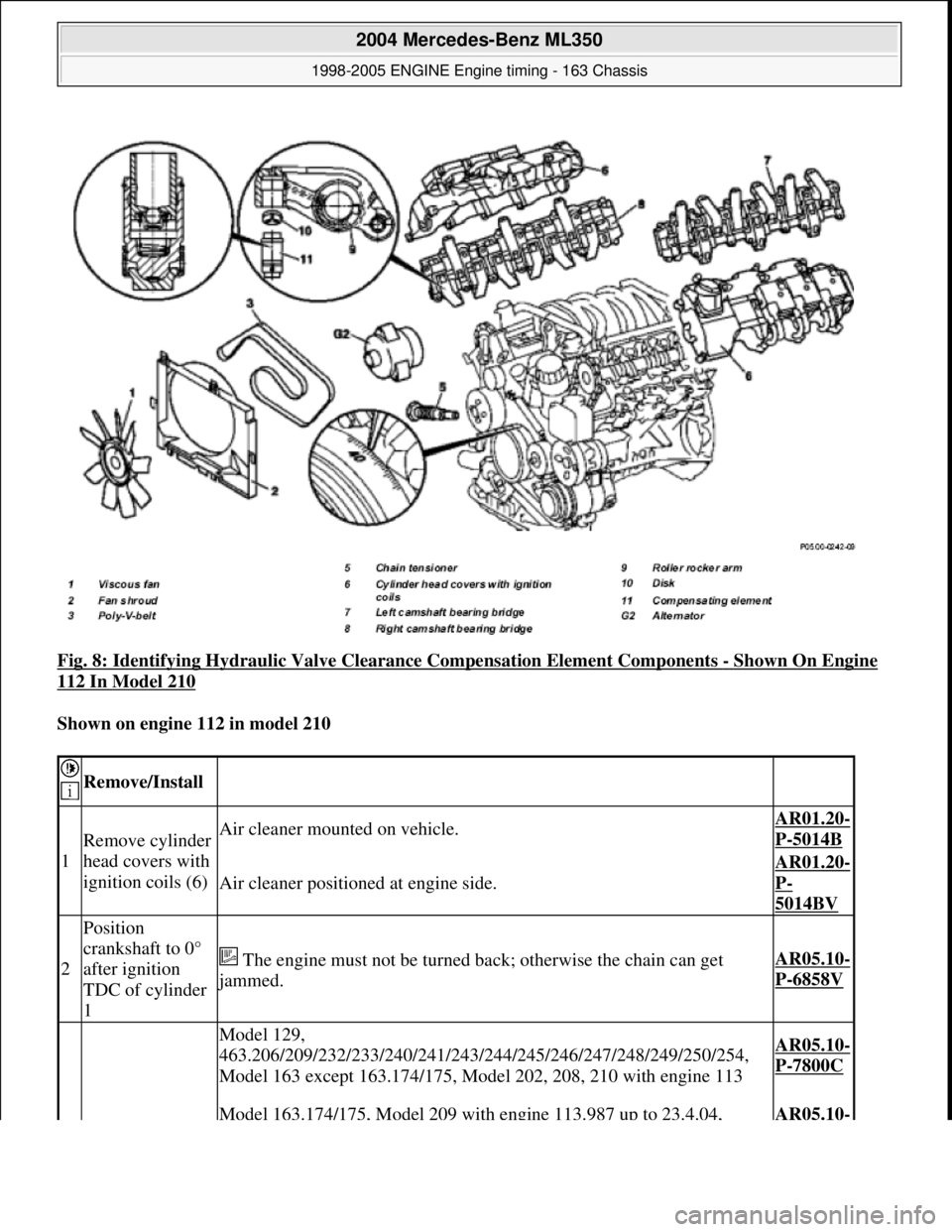
Fig. 8: Identifying Hydraulic Valve Clea rance Compensation Element Components - Shown On Engine
112 In Model 210
Shown on engine 112 in model 210
Remove/Install
1
Remove cylinder
head covers with
ignition coils (6)Air cleaner mounted on vehicle.AR01.20-
P-5014B
Air cleaner positione d at engine side.
AR01.20-
P-
5014BV
2
Position
crankshaft to 0°
after ignition
TDC of cylinder
1
The engine must not be turned back; otherwise the chain can get
jammed.
AR05.10-
P-6858V
Model 129,
463.206/209/232/233/240/241/243/2 44/245/246/247/248/249/250/254,
Model 163 except 163.174/175, Model 202, 208, 210 with engine 113AR05.10-
P-7800C
Model 163.174/175, Model 209 with engine 113.987 up to 23.4.04, AR05.10-
2004 Mercedes-Benz ML350
1998-2005 ENGINE Engine timing - 163 Chassis
me
Saturday, October 02, 2010 3:39:37 PMPage 10 © 2006 Mitchell Repair Information Company, LLC.
Page 2254 of 4133
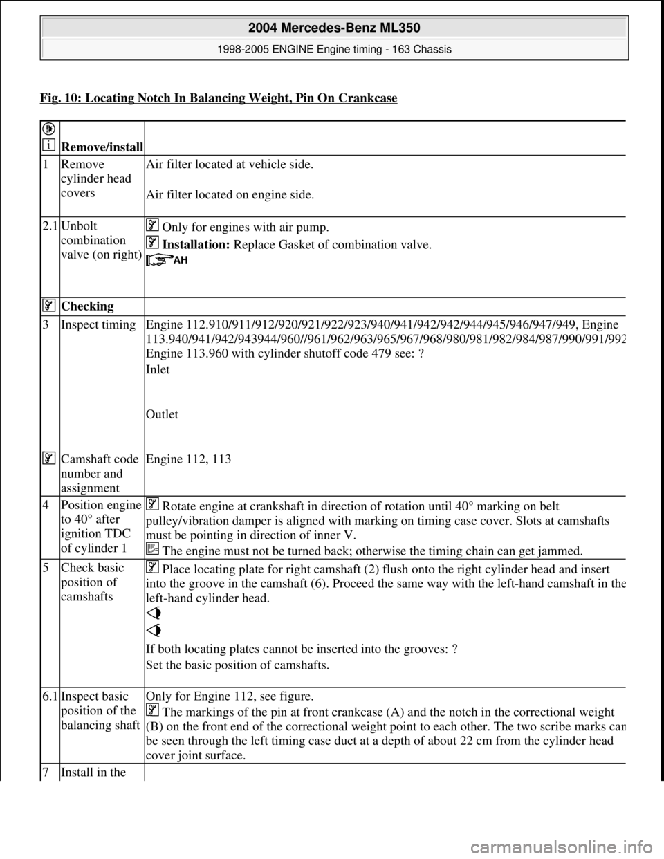
Fig. 10: Locating Notch In Balancing Weight, Pin On Crankcase
Remove/install
1Remove
cylinder head
covers Air filter located
at vehicle side.
Air filter located on engine side.
2.1Unbolt
combination
valve (on right) Only for engines with air pump.
Installation: Replace Gasket of combination valve.
Checking
3Inspect timing Engine 112.910/911/912/920/921/ 922/923/940/941/942/942/944/945/946/947/949, Engine
113.940/941/942/943944/960//961/962/963/965/ 967/968/980/981/982/984/987/990/991/99
2
Engine 113.960 with cylinder shutoff code 479 see: ?
Inlet
Outlet
Camshaft code
number and
assignmentEngine 112, 113
4Position engine
to 40° after
ignition TDC
of cylinder 1 Rotate engine at crankshaft in direct ion of rotation until 40° marking on belt
pulley/vibration damper is aligned with mark ing on timing case cover. Slots at camshafts
must be pointing in di rection of inner V.
The engine must not be turned back; otherwise the timing chain can get jammed.
5Check basic
position of
camshafts Place locating plate for right camshaft (2) fl
ush onto the right cylinder head and insert
into the groove in the camshaft (6). Proceed the same way with the left-hand camshaft in th
e
left-hand cylinder head.
If both locating plates cannot be inserted into the grooves: ?
Set the basic position of camshafts.
6.1Inspect basic
position of the
balancing shaftOnly for Engine 112, see figure.
The markings of the pin at front crankcase (A) and the notch in the correctional weight
(B) on the front end of the corr ectional weight point to each ot her. The two scribe marks ca
n
be seen through the left timing case duct at a depth of about 22 cm from the cylinder head
cover joint surface.
7Install in the
2004 Mercedes-Benz ML350
1998-2005 ENGINE Engine timing - 163 Chassis
me
Saturday, October 02, 2010 3:39:37 PMPage 13 © 2006 Mitchell Repair Information Company, LLC.
Page 2277 of 4133
2Remove spark plugs To ensure that the
engine can be easily
cranked when drawing in
the timing chain, and to
avoid the timing chain
jumping across.
Remove only one spark
plug at each cylinder.
Replace spark plugsModel 463.AP15.10-P-1580GA
Model 129.AP15.10-P-1580A
Models 202, 208, 210 with
engine 112.
Models 163.AP15.10-P-1580GH
3Remove cylinder head
coversAir filter locat ed at vehicle
side.AR01.20-P-5014B
Air filter located on
engine side.AR01.20-P-5014BV
4Remove viscous-drive fan. Right-hand thread!AR20.40-P-5660C
5Remove fan shroud On model 163 unscrew
bolts at bottom of fan
shroud.
Model 463.AR20.40-P-6800V
6Position engine at a 40°
crank angle before
ignition TDC of cylinder
1. Engine must not be
cranked back.
The notches of the
camshafts must be
pointing in the direction of
the inner V.
It must be possible to
easily insert the two
locking plates.
If this is not possible: ?
Set the basic position of
camshafts.AR05.20-P-6020AU
The copper tabs of the
timing chain must be
aligned with the markings
on the camshaft sprockets.
Because of the unevenly
long travel of the timing
chain it may be necessary
to crank the engine as
much as 14 times until the
copper tabs are aligned
with the markings on the
2004 Mercedes-Benz ML350
1998-2005 ENGINE Engine timing - 163 Chassis
me
Saturday, October 02, 2010 3:39:37 PMPage 36 © 2006 Mitchell Repair Information Company, LLC.
Page 2299 of 4133
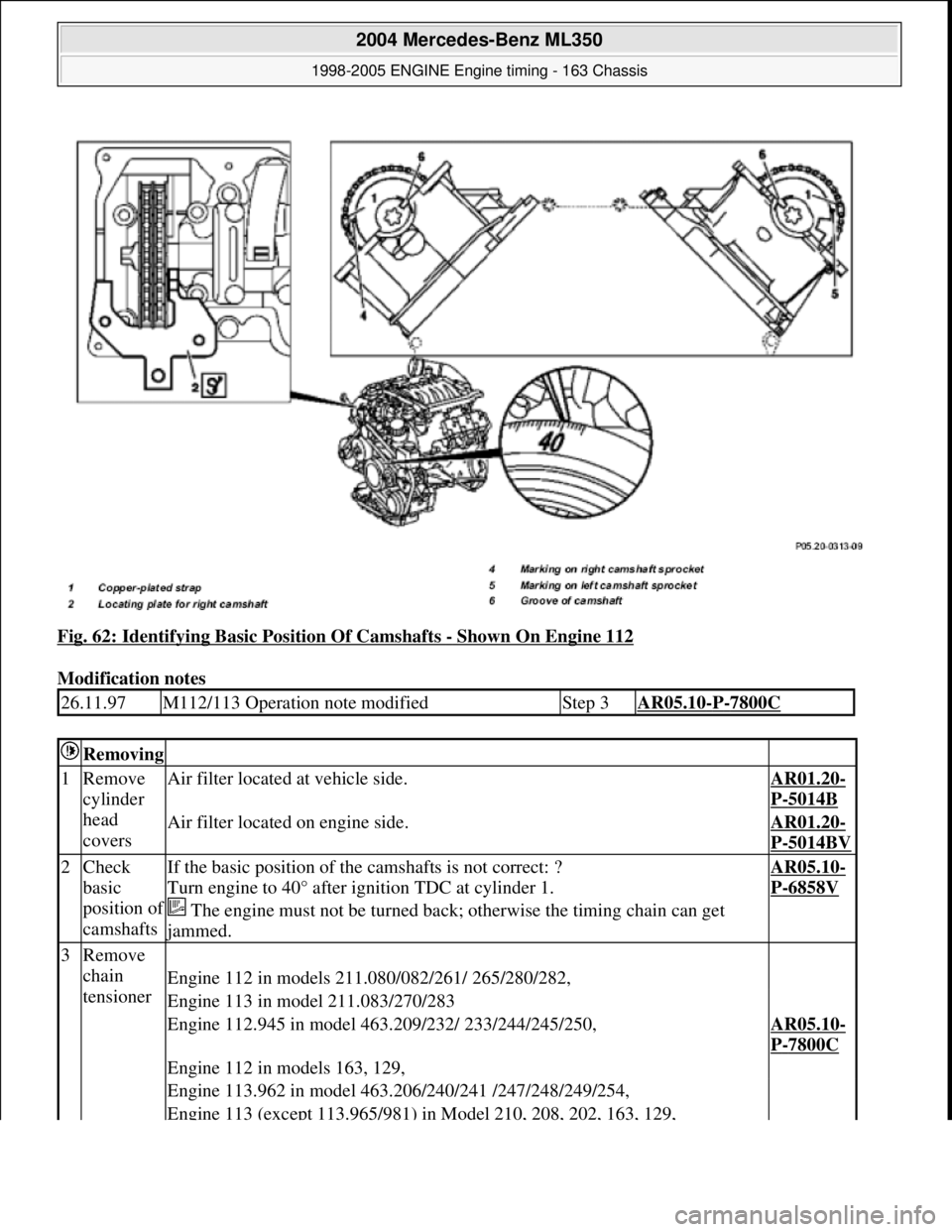
Fig. 62: Identifying Basic Position Of Camshafts - Shown On Engine 112
Modification notes
26.11.97M112/113 Operation note modifiedStep 3AR05.10-P-7800C
Removing
1Remove
cylinder
head
coversAir filter located at vehicle side.AR01.20-
P-5014B
Air filter located on engine side.AR01.20-
P-5014BV
2Check
basic
position o
f
camshafts
If the basic position of the camshafts is not correct: ?
Turn engine to 40° after ignition TDC at cylinder 1.
The engine must not be turned back; otherwise the timing chain can get
jammed.
AR05.10-
P-6858V
3Remove
chain
tensioner
Engine 112 in models 211.080/082/261/ 265/280/282,
Engine 113 in model 211.083/270/283
Engine 112.945 in model 463.209/232/ 233/244/245/250,AR05.10-
P-7800C
Engine 112 in models 163, 129,
Engine 113.962 in model 463.206/240/241 /247/248/249/254,
Engine 113 (except 113.965/981) in Model 210, 208, 202, 163, 129,
2004 Mercedes-Benz ML350
1998-2005 ENGINE Engine timing - 163 Chassis
me
Saturday, October 02, 2010 3:39:38 PMPage 58 © 2006 Mitchell Repair Information Company, LLC.
Page 2300 of 4133
Engine 113.982 in model 463.243/246
Engine 112 in Model 170, 202, 203, 208, 209, 210,AR05.10-
P-7800CA
Engine 113 in models 163.174/175, 209
Engine 112 in Model 211.061 /065, 220, 230.467,AR05.10-
P-
7800AM
Engine 113 in models 211.070/076/276,
215.373/374/375,220.070/073/074/075 /083/ 084/170/173/174/175/183/184/875,
230.474/475
4Remove
camshaft
Hall
sensor
Engine 112 in models 211.080/082/261/265 /280/282,
Engine 113 in model 211.083/270/283
Engine 112.945 in model 463.209/232/233 /244/245/250,AR15.10-
P-2000A
Engine 112 in Model 129, 163, 170, 202, 203, 208, 209.361/365/461/465, 210,
211.061 /065, 220, 230.467,
Engine 113 (except 113.990/991) in Model 129, 163, 202, 208,
209.375/376/475/476, 210, 211.070, 215, 220, 230.474/475,
Engine 113.962 in model 463.206/240/241 /247/248/249/254,
Engine 113.982 in model 463.243/246
Engine 113.990 in model 211.076/276,
Engine 113.991 in models 215.374, 220.074 /174AR15.10-
P-
2000RVK
5Remove
right-hand
camshaft
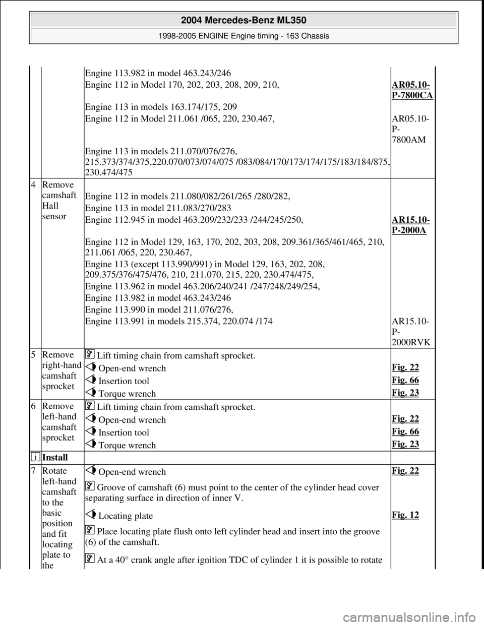
sprocket Lift timing chain from camshaft sprocket.
Open-end wrenchFig. 22
Insertion toolFig. 66
Torque wrenchFig. 23
6Remove
left-hand
camshaft
sprocket Lift timing chain from camshaft sprocket.
Open-end wrenchFig. 22
Insertion toolFig. 66
Torque wrenchFig. 23
Install
7Rotate
left-hand
camshaft
to the
basic
position
and fit
locating
plate to
the Open-end wrenchFig. 22
Groove of camshaft (6) must point to the center of the cylinder head cover
separating surface in direction of inner V.
Locating plateFig. 12
Place locating plate flush onto left cylinder head and insert into the groove
(6) of the camshaft.
At a 40° crank angle afte r ignition TDC of cylinder 1 it is possible to rotate
2004 Mercedes-Benz ML350
1998-2005 ENGINE Engine timing - 163 Chassis
me
Saturday, October 02, 2010 3:39:38 PMPage 59 © 2006 Mitchell Repair Information Company, LLC.
Page 2301 of 4133
camshaftthe camshaft without th e valves coming into contact with the pistons.
8Rotate
right
camshaft
in basic
position
and insert
locating
plate for
right
camshaft
(2) in the
camshaft Open-end wrenchFig. 22
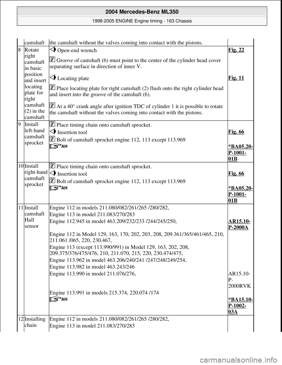
Groove of camshaft (6) must point to the center of the cylinder head cover
separating surface in direction of inner V.
Locating plateFig. 11
Place locating plate for right camshaft (2) flush onto the right cylinder head
and insert into the groove of the camshaft (6).
At a 40° crank angle afte r ignition TDC of cylinder 1 it is possible to rotate
the camshaft without th e valves coming into contact with the pistons.
9Install
left-hand
camshaft
sprocket Place timing chain onto camshaft sprocket.
Insertion toolFig. 66
Bolt of camshaft sprock et engine 112, 113 except 113.969
*BA05.20-
P-1001-
01B
10Install
right-hand
camshaft
sprocket Place timing chain onto camshaft sprocket.
Insertion toolFig. 66
Bolt of camshaft sprock et engine 112, 113 except 113.969
*BA05.20-
P-1001-
01B
11Install
camshaft
Hall
sensorEngine 112 in models 211.080/082/261/265 /280/282,
Engine 113 in model 211.083/270/283
Engine 112.945 in model 463.209/232/233 /244/245/250,AR15.10-
P-2000A
Engine 112 in Model 129, 163, 170, 202, 203, 208, 209.361/365/461/465, 210,
211.061 /065, 220, 230.467,
Engine 113 (except 113.990/991) in Model 129, 163, 202, 208,
209.375/376/475/476, 210, 211.070, 215, 220, 230.474/475,
Engine 113.962 in model 463.206/240/241 /247/248/249/254,
Engine 113.982 in model 463.243/246
Engine 113.990 in model 211.076/276,AR15.10-
P-
2000RVK
Engine 113.991 in models 215.374, 220.074 /174
*BA15.10-
P-1002-
03A
12Installing
chain Engine 112 in models 211.080/082/261/265 /280/282,
Engine 113 in model 211.083/270/283
2004 Mercedes-Benz ML350
1998-2005 ENGINE Engine timing - 163 Chassis
me
Saturday, October 02, 2010 3:39:38 PMPage 60 © 2006 Mitchell Repair Information Company, LLC.