Page 2156 of 4133

NOTES ON AVOIDING DAMAGE TO IGNITION SYSTEM - AH15.10-P-0002-01D
Engine 104, 111, 112, 113, 119, 120, 156, 271
To avoid damage to control unit connect and disconnect the two connectors on control unit only when
ignition is switched off.
Terminal 1 of ignition coils must not be short-circuited to GND, e.g. as anti-theft protection.
Install only original ignition system components.
Do not operate ignition system at starting speed unless all of the ignition cables are connected.
No tests such as holding ignition cable 4 at a distance to GND, unplugging a spark plug connector or
pulling cable 4 out of the ignition coils, may be performed at starting speed or when the engine is
running.
Every high voltage circuit must be loaded with at least 2 kohms (spark plug connector).
If it is necessary to test the ignition spark when providing roadside assistance, this must only be done with
a spark plug at a cylinder ignition cable. Ensure that the spark plug has good contact to ground.
Before working at cranking speed, e.g. checking compression pressure, switch off ignition and disconnect
connector "2" from control unit.
Engine 120 has two fuel injection and ignition systems.
Use of testers
Only connect and disconnect secondary measuring sensor to corresponding ignition cables when vertical
engine and ignition are switched off.
If the shot-circuit protection is operated (cylinder comparison) and the engine stays upright, it is not
possible to conduct the test with this test instrument.
Do not connect test lamp to ignition coil terminals 1 and 15.
NOTES ON IGNITION COIL CHARACTERISTICS OF IGNITION SYSTEMS - AH15.10-P-1001-01A
Engine 104, 111, 112, 113, 119, 120
In the case of the twin-spark ignition coil with kV pickup in ignition systems ME-SFI 2.1 and HFM-SFI, no
measurement facilit
y exists at the ignition coil using the kV pickup although a kV pickup is fitted. It is only
damage to ignition system
Notes on avoiding
damage to ignition systemENGINE 104, 111, 112, 113,
119, 120, 156, 271, 112 mit
Benzin-Einspritz- und
Zundsystem MEAH15.10-P-0002-01D
Notes for ceramic glow
plugsENGINE 646.8, 642AH15.20-P-0001-01A
2001 Mercedes-Benz ML320
1998-2005 ENGINE Electrical System - Engine - 163 Chassis
me
Saturday, October 02, 2010 3:18:54 PMPage 2 © 2006 Mitchell Repair Information Company, LLC.
Page 2157 of 4133

possible to test the primary ignition circuit with adapter cable A.
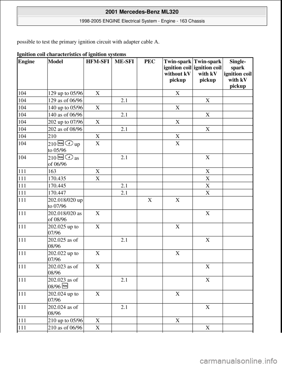
Ignition coil characteristics of ignition systems
EngineModelHFM-SFIME-SFIPECTwin-spark
i
gnition coil
without kV
pickup
Twin-spark
i
gnition coil
with kV
pickup
Single-
spark
i
gnition coil
with kV
pickup
104129 up to 05/96X X
104129 as of 06/96 2.1 X
104140 up to 05/96X X
104140 as of 06/96 2.1 X
104202 up to 07/96X X
104202 as of 08/96 2.1 X
104210X X
104210 up
to 05/96X X
104210 as
of 06/96 2.1 X
111163X X
111170.435X X
111170.445 2.1 X
111170.447 2.1 X
111202.018/020 up
to 07/96 XX
111202.018/020 as
of 08/96X X
111202.025 up to
07/96X X
111202.025 as of
08/96 2.1 X
111202.022 up to
07/96X X
111202.023 as of
08/96X X
111202.023 as of
08/96 2.1 X
111202.024 up to
07/96X X
111202.024 as of
08/96 2.1 X
111210 up to 05/96X X
111210 as of 06/96X X
2001 Mercedes-Benz ML320
1998-2005 ENGINE Electrical System - Engine - 163 Chassis
me
Saturday, October 02, 2010 3:18:54 PMPage 3 © 2006 Mitchell Repair Information Company, LLC.
Page 2158 of 4133
GENERAL NOTES ON CONTACTLESS HIGH VOLTAGE DISTRIBUTION - AH15.10-P-1002-01WA
Engine 112, 113 with ME-SFI fuel injection and ignition system
The ignition system can be tested at the primary side and secondary side. It is only possible to test ignition
circuit a and ignition circuit b one after the other.
The ignition coils are fitted as standard with cast mounts for the secondary adapters (kV pickup C). The primary
i
gnition voltage curve can be plotted with a primary adapter cable (D).
112163 2.0 X
112202 2.0 X
112208 2.0 X
112210 2.0 X
112220 2.0 X
113163 2.0 X
113202 2.0 X
113208 2.0 X
113210 2.0 X
113220 2.0 X
119.982129 1.0 X
119.980140 1.0 X
119.981140 1.0 X
119210 1.0 X
120.983129 1.0 X
120.982140 1.0 X
2001 Mercedes-Benz ML320
1998-2005 ENGINE Electrical System - Engine - 163 Chassis
me
Saturday, October 02, 2010 3:18:54 PMPage 4 © 2006 Mitchell Repair Information Company, LLC.
Page 2159 of 4133

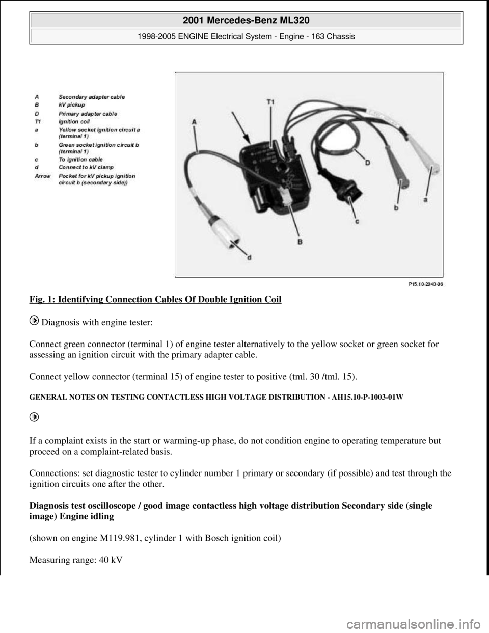
Fig. 1: Identifying Connection Cables Of Double Ignition Coil
Diagnosis with engine tester:
Connect green connector (terminal 1) of engine tester alternatively to the yellow socket or green socket for
assessing an ignition circuit with the primary adapter cable.
Connect yellow connector (terminal 15) of engine tester to positive (tml. 30 /tml. 15).
GENERAL NOTES ON TESTING CONTACTLESS HIGH VOLTAGE DISTRIBUTION - AH15.10-P-1003-01W
If a complaint exists in the start or warming-up phase, do not condition engine to operating temperature but
proceed on a complaint-related basis.
Connections: set diagnostic tester to cylinder number 1 primary or secondary (if possible) and test through the
ignition circuits one after the other.
Diagnosis test oscilloscope / good image contactless high voltage distribution Secondary side (single
image) Engine idling
(shown on engine M119.981, cylinder 1 with Bosch ignition coil)
Measurin
g range: 40 kV
2001 Mercedes-Benz ML320
1998-2005 ENGINE Electrical System - Engine - 163 Chassis
me
Saturday, October 02, 2010 3:18:54 PMPage 5 © 2006 Mitchell Repair Information Company, LLC.
Page 2162 of 4133
IGNITION COILS, LOCATION - GF15.10-P-3102-01A
Fig. 5: Identifying Cylinder 1 To 6 Ignition Coil - Location On Engine 112
Spark plugs, locationOne or two spark plugs are
located in the cylinder head
per cylinder.
Spark plugs, taskThe spark plugs ignite the
suctioned and compressed
fuel-air mixture due to arcing
between the electrodes.
Spark plugs, designIn the manufacturer's specific
type symbols, all the spark
plug features are assigned (e.
g. heat rating, shape of
seating, thread, width across
flats, electrode material,
spark position).
Spark plugs, functionThe ignition voltage travels to
the spark plugs from directly
connected ignition coils or
over the ignition lines from
the ignition coils causing
arcing in the air gap between
the center and ground
electrodes.
2001 Mercedes-Benz ML320
1998-2005 ENGINE Electrical System - Engine - 163 Chassis
me
Saturday, October 02, 2010 3:18:54 PMPage 8 © 2006 Mitchell Repair Information Company, LLC.
Page 2163 of 4133

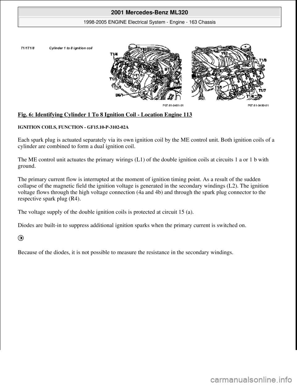
Fig. 6: Identifying Cylinder 1 To 8 Ignition Coil - Location Engine 113
IGNITION COILS, FUNCTION - GF15.10-P-3102-02A
Each spark plug is actuated separately via its own ignition coil by the ME control unit. Both ignition coils of a
cylinder are combined to form a dual ignition coil.
The ME control unit actuates the primary wirings (L1) of the double ignition coils at circuits 1 a or 1 b with
ground.
The primary current flow is interrupted at the moment of ignition timing point. As a result of the sudden
collapse of the magnetic field the ignition voltage is generated in the secondary windings (L2). The ignition
voltage flows through the high voltage connection (4a and 4b) and through the spark plug connector to the
respective spark plug (R4).
The voltage supply of the double ignition coils is protected at circuit 15 (a).
Diodes are built-in to suppress additional ignition sparks when the primary current is switched on.
Because of the diodes, it is not possible to measure the resistance in the secondary windings.
2001 Mercedes-Benz ML320
1998-2005 ENGINE Electrical System - Engine - 163 Chassis
me
Saturday, October 02, 2010 3:18:54 PMPage 9 © 2006 Mitchell Repair Information Company, LLC.
Page 2164 of 4133
Fig. 7: Identifying Ignition Coils, Function
IGNITION COILS, LO CATION/TASK/DESIGN/FUNCTION - GF15.10-P-3102A
ENGINE
112.910 /911 /912 /913 /914 /916 /917 /920 /921 /922 /923 /940 /941 /942 /943 /944 /946 /947 /949 /953 /954 /9
5
ENGINE 113.940 /941 /942 /943 /948 /960 /961 /963 /965 /966 /967 /968 /969
Fig. 8: Identifying Ignition Coil Components
- Shown On Engine 112
2001 Mercedes-Benz ML320
1998-2005 ENGINE Electrical System - Engine - 163 Chassis
me
Saturday, October 02, 2010 3:18:54 PMPage 10 © 2006 Mitchell Repair Information Company, LLC.
Page 2165 of 4133
ME-SFI IGNITION SYSTEM FUNCTION DIAGRAM - GF15.12-P-0001-01A
Fig. 9: Identifying ME-SFI Ignition System Components - Engine 112
ME-SFI IGNITION SYSTEM FUNCTION DIAGRAM - GF15.12-P-0001-01B
Ignition coils, location GF15.10-P-3102-01A
Ignition coils, taskSupplying adequate
ignition energy in all
operating conditions for
the particular ignition
circuit.
Ignition coils, designOne double ignition coil
for each cylinder. Attached
to cylinder head cover.
Ignition coils, function GF15.10-P-3102-02A
2001 Mercedes-Benz ML320
1998-2005 ENGINE Electrical System - Engine - 163 Chassis
me
Saturday, October 02, 2010 3:18:54 PMPage 11 © 2006 Mitchell Repair Information Company, LLC.