1997 MERCEDES-BENZ ML430 ignition
[x] Cancel search: ignitionPage 1781 of 4133
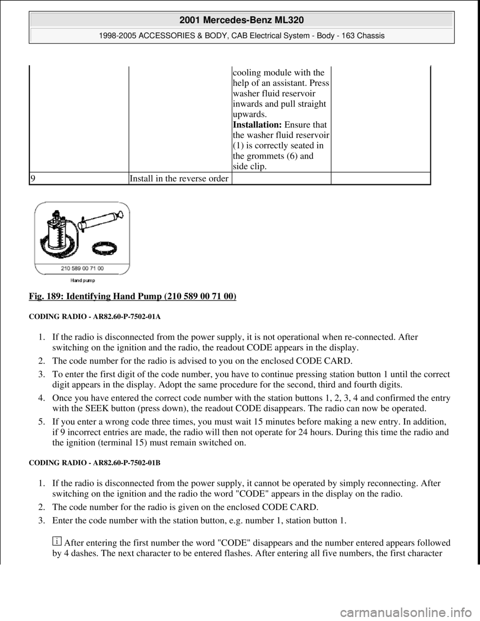
Fig. 189: Identifying Hand Pump (210 589 00 71 00)
CODING RADIO - AR82.60-P-7502-01A
1. If the radio is disconnected from the power supply, it is not operational when re-connected. After
switching on the ignition and the radio, the readout CODE appears in the display.
2. The code number for the radio is advised to you on the enclosed CODE CARD.
3. To enter the first digit of the code number, you have to continue pressing station button 1 until the correct
digit appears in the display. Adopt the same procedure for the second, third and fourth digits.
4. Once you have entered the correct code number with the station buttons 1, 2, 3, 4 and confirmed the entry
with the SEEK button (press down), the readout CODE disappears. The radio can now be operated.
5. If you enter a wrong code three times, you must wait 15 minutes before making a new entry. In addition,
if 9 incorrect entries are made, the radio will then not operate for 24 hours. During this time the radio and
the ignition (terminal 15) must remain switched on.
CODING RADIO - AR82.60-P-7502-01B
1. If the radio is disconnected from the power supply, it cannot be operated by simply reconnecting. After
switching on the ignition and the radio the word "CODE" appears in the display on the radio.
2. The code number for the radio is given on the enclosed CODE CARD.
3. Enter the code number with the station button, e.g. number 1, station button 1.
After entering the first number the word "CODE" disappears and the number entered appears followed
by 4 dashes. The next character to be entered flashes. After entering all five numbers, the first character
cooling module with the
help of an assistant. Press
washer fluid reservoir
inwards and pull straight
upwards.
Installation: Ensure that
the washer fluid reservoir
(1) is correctly seated in
the grommets (6) and
side clip.
9Install in the reverse order
2001 Mercedes-Benz ML320
1998-2005 ACCESSORIES & BODY, CAB Electrical System - Body - 163 Chassis
me
Saturday, October 02, 2010 3:30:09 PMPage 286 © 2006 Mitchell Repair Information Company, LLC.
Page 1782 of 4133
starts flashing again. In this state the code number can be written over as frequently as desired. A
correction can be made only by entering the complete code number again.
4. Confirm code number:
Press TUNE, AUTO/SEEK or SC button. The radio automatically switches on and indicates the radio
station or frequency stored with station button 1.
5. If an incorrect code number is entered and confirmed, the word "CODE" appears again on the display. If
an incorrect code is entered three times the word "WAIT" appears on the display and the radio locks up
for approx. 10 min. If the code is entered incorrectly three times again the radio locks up again for 10
min. Three more incorrect entries (a total of 9 incorrect attempts) increase the lock-up time to 60 min.
Another three incorrect entries lock up the radio for another 60 min.
The waiting time runs only when the radio is switched on.
CODING RADIO - AR82.60-P-7502-01GH
1. If the power supply to the radio is interrupted the radio will not operate when reconnected. After
switching on the ignition the word "CODE" appears on the radio display.
2. The code number for this radio is given on the included code card.
3. Enter the code number with the station buttons, e.g. number 1 = station button 1..
4. After entering the first digit the word "CODE" disappears and the number entered is displayed followed
by four dashes. Enter the next numbers with the corresponding station buttons. After entering the five
digit code number compare the code number with the number on the display. At this point the code
number can be written over as frequently as necessary for correction. If the wrong code number has been
entered, enter the entire code number again.
5. Confirm entry of correct code number with " < " or " > " button.
6. If the wrong code number has been entered and confirmed the word "CODE" appears again on the display
and the code must be entered again.
7. After entering the code incorrectly three times the word "WAIT" appears on the display and the radio is
disabled for approx. 10 minutes. After entering the incorrect code three times again the radio is disabled
for approx. 60 minutes.
The disable time runs down only with the radio switched off.
REMOVE/INSTALL RADIO - AR82.60-P-7502EA
MODEL 129 with single-block unit, 2nd generation two-component unit control element and MB radios
MODEL 163 with CODE (257) Hi-Line radio with CODE (259) Premium radio with Bose sound system
with CODE (352) COMAND operating and display system with CODE (353) Audio 30 APS with CODE
(357) Navigation system - additional unit with CODE (522) Modular control system (MCS) radio USA
with CODE (750) MB Audio 30 RDS radio with CODE (752) Becker Mexico 2000 radio with traffic news
decoder with CODE (753) MB Audio 30 RDS radio with CODE (756) MB Audio 10 RDS radio with CD
compartment
2001 Mercedes-Benz ML320
1998-2005 ACCESSORIES & BODY, CAB Electrical System - Body - 163 Chassis
me
Saturday, October 02, 2010 3:30:09 PMPage 287 © 2006 Mitchell Repair Information Company, LLC.
Page 1904 of 4133
with the automatic
button (A) (allow
running letters to run
until they finish)
Press multifunction
button below (*)Enter street name.....
Enter closest digitalized
street name or
CENTER or TRAIN
STATION with the
multifunction buttonsTrain station
A number in front of
the street indicates that
there are several streets
with the same name
Press automatic button
(A) repeatedly until the
right street name
appears (allow running
letters to run until they
finish)
Press multifunction
button below (*) until
message appears. . . .Please switch off radio and
ignition for 1 minute
First switch off unit
and then ignition
10Start engine Drive vehicle
outside under free sky
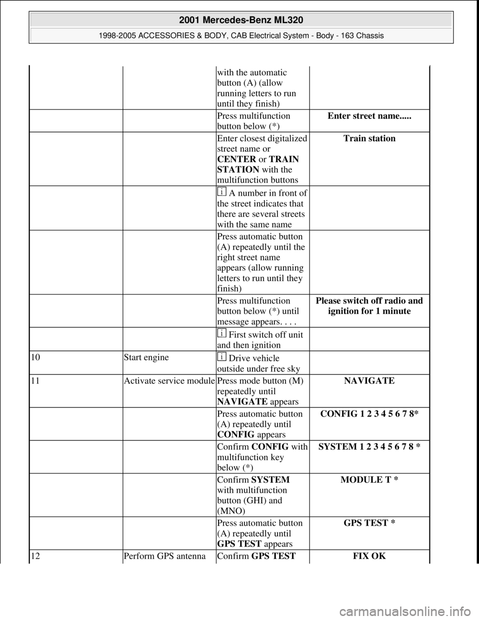
11Activate service modulePress mode button (M)
repeatedly until
NAVIGATE appearsNAVIGATE
Press automatic button
(A) repeatedly until
CONFIG appearsCONFIG 1 2 3 4 5 6 7 8*
Confirm CONFIGwith
multifunction key
below (*)SYSTEM 1 2 3 4 5 6 7 8 *
Confirm SYSTEM
with multifunction
button (GHI) and
(MNO)MODULE T *
Press automatic button
(A) repeatedly until
GPS TEST appearsGPS TEST *
12Perform GPS antenna Confirm GPS TEST FIX OK
2001 Mercedes-Benz ML320
1998-2005 ACCESSORIES & BODY, CAB Electrical System - Body - 163 Chassis
me
Saturday, October 02, 2010 3:30:13 PMPage 409 © 2006 Mitchell Repair Information Company, LLC.
Page 2006 of 4133

AD54.30-P-6000-04GH
CAN data lines test electrics IC
Model 163
t
A
Scope of test
Measuring instrument/
Test connection
Operation/
Requirement
Specified value
D
Possible cause/
Remedy
1.0
CAN data buses
Resistance
9
w
(B.9)
A1
bL
10
(B.10)
Ignition:
OFF
Coupling "B" (12-pin)
disconnected
(N3 is connected to CAN)
approx.
120
WD
CAN:
-
//
-
,
d e
D
N3
Value in order:
#
t
1.1
1.1
CAN data buses
Voltages, low line
oc
A1
L
10
(B.10)
Ignition: ON
approx. 2.3 V
D
N3
Value in order:
#
t
1.2
1.2
CAN data buses
Voltages, high line
oc
A1
L
9
(B.9)
Ignition: ON
approx. 2.6 V
D
N3
Copyright DaimlerChrysler AG 05.06.2006 CD-Ausgabe G/10/04 . This WIS print-out will not be recorde
d by Modification services.
Page 1
Page 2007 of 4133

AD54.30-P-6000-05GH
CAN input resistance, testing electrical
system of IC
Model 163
t
A
Scope of test
Measuring instrument/
Test connection
Operation/
Requirement
Specified value
D
Possible cause/
Remedy
1.0Instrument cluster (A1)
CAN input resistance
9
v
(B.9)
A1
bK
10
(B.10)
Ignition:
OFF
Coupling "B" (12-pin)
disconnected
approx.
120
WD
A1
Copyright DaimlerChrysler AG 05.06.2006 CD-Ausgabe G/10/04 . This WIS print-out will not be recorde
d by Modification services.
Page 1
Page 2034 of 4133
GF54.30-P-3007A
Charge indicator lamp, exterior lamp failure
24.10.96
MODEL
129, 140 as of 1.6.96,
163, 168, 170,
202 as of 1.8.96,
208 up to 31.7.99,
210 as of 1.6.96 up to 30.6.99
P54.30-0517-06
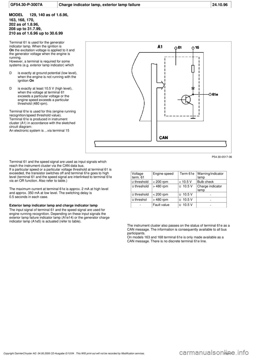
Terminal 61 is used for the generator
indicator lamp. When the ignition is
On
the excitation voltage is applied to it and
the generator voltage when the engine is
running.
However, a terminal is required for some
systems (e.g. exterior lamp indicator) which
D
is exactly at ground potential (low level),
when the engine is not running with the
ignition
On
D
is exactly at least 10.5 V (high level),
when the voltage at terminal 61
exceeds a particular voltage or the
engine speed exceeds a particular
threshold (480 rpm).
Terminal 61e is used for this (engine running
recognition/speed threshold value).
Terminal 61e is produced in instrument
cluster (A1) in accordance with the sketched
circuit diagram:
An electronic system is ...via terminal 15
Terminal 61 and the speed signal are used as input signals which
reach the instrument cluster via the CAN data bus.
If a particular speed or a particular voltage threshold at terminal 61 is
exceeded, the transistor switches off and terminal 61e goes to high
level (terminal 61 and the speed signal are interlinked to terminal 61e
via an OR function. Also refer to table.)
The maximum current at terminal 61e is approx. 2 mA at high level
and approx. 350 mA at low level. The switching delay is
0.5 seconds in each case.
Exterior lamp indicator lamp and charge indicator lamp
The input signal of terminal 61 and the speed signal are used for
engine running recognition. Depending on these input signals the
exterior lamp failure indicator lamp (A1e14) or the generator charge
indicator lamp (A1e5) is actuated (refer to table).
The instrument cluster also passes on the status of terminal 61e as a
CAN message. The information is consequently available to all bus
participants.
On models 163 and 168 terminal 61e is only made available as a
CAN message. There is no discrete terminal 61e line.
Voltage
term. 61
Engine speed
Term 61e
Warning/indicator
lamp
U
threshold
< 200 rpm
< 10.5 V
Bulb check
U
threshold
> 480 rpm
U
10.5 V
Charge indicator
lamp
U
threshold
< 200 rpm
U
10.5 V
-
U
threshol
> 480 rpm
U
10.5 V
-
-
Fault value
U
10.5 V
-
Copyright DaimlerChrysler AG 04.06.2006 CD-Ausgabe G/10/04 . This WIS print-out will not be recorde
d by Modification services.
Page 1
Page 2037 of 4133
Fig. 1: Drive Belt Routing
Courtesy of MERCEDES-BENZ OF NORTH AMERICA.
TROUBLE SHOOTING
PRELIMINARY INSPECTION
Verify customer complaint by operating system. Visually inspect for obvious signs of mechanical and electrical
damage. Check generator belt tension and condition. Ensure that battery voltage is within specifications. Inspect
for blown fuses and damaged relays.
Verify ground connection integrity between engine, body, battery and generator. Check for damaged wiring
harnesses and/or switches. Check for a broken or partially broken wire inside insulation, which could cause
system malfunction but prove good in a continuity/voltage check with system disconnected. Ensure any
aftermarket electronic equipment is properly installed. If fault is found, repair as necessary. If no fault is found,
check for conditions that might cause an intermittent situation.
SERVICE PRECAUTIONS
BATTERY DISCONNECT/CONNECT
Disconnect Procedures
1. On vehicles not equipped with TELE AID, go to step 5 . Vehicles equipped with TELE AID, switch
TELE AID into service mode by turning ignition ON.
2. Turn ON telephone and enter code "*#4610#" on handset.
3. Confirm that "No Telematics Service" appears on handset with okay.
4. Turn OFF handset.
5. Turn OFF ignition.
6. Open hood and open snap fasteners (1) on dust filter housing. See Fig. 2
.
7. Remove dust filter housing (2) exposing battery.
8. If not using quiescent current retention unit, go to step 14 . If using quiescent current retention unit, go to
next step.
9. Connect quiescent current retention unit by switching on quiescent current retention unit (7) and then first
connecting positive terminal (8) and negative terminal (9) of retention unit to positive cable and battery
ground (W10). See Fig. 3
.
10. On vehicles equipped with TELE AID, remove luggage compartment cargo anchoring lugs and remove
floor paneling.
11. Remove screws (1). See Fig. 4
.
12. Dismantle cover from TELE AID control module (A35/8).
13. Disconnect connection coupling for back up battery and remove back up battery.
14. Disconnect ne
gative battery cable (1) and insulate terminal. See Fig. 5. NOTE: Numbers and letters in text refer to numbers and letters in figures.
2001 Mercedes-Benz ML320
2001-04 STARTING & CHARGING SYSTEMS Generators & Regulators - 163 Chassis
me
Saturday, October 02, 2010 3:20:31 PMPage 3 © 2006 Mitchell Repair Information Company, LLC.
Page 2041 of 4133
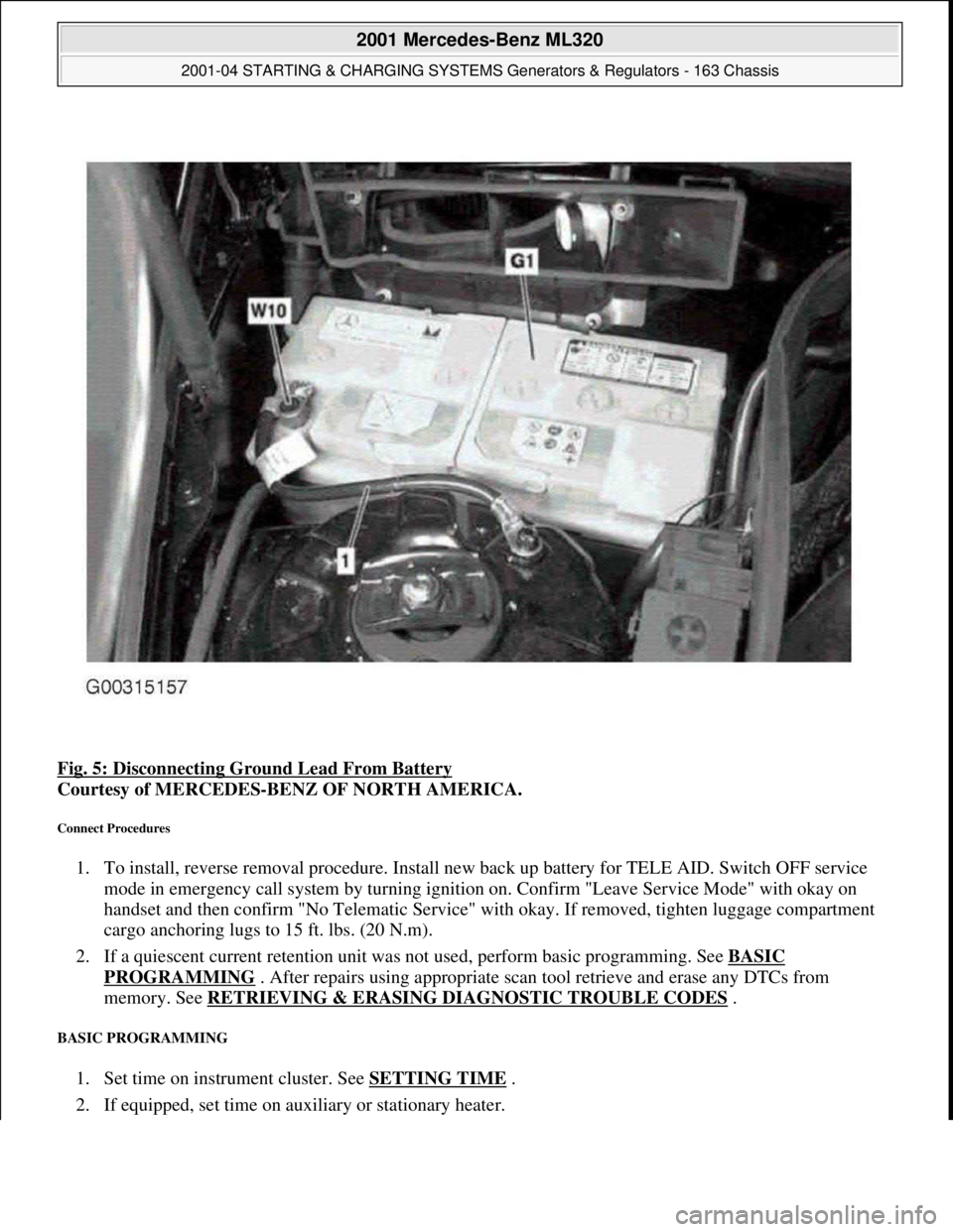
Fig. 5: Disconnecting Ground Lead From Battery
Courtesy of MERCEDES-BENZ OF NORTH AMERICA.
Connect Procedures
1. To install, reverse removal procedure. Install new back up battery for TELE AID. Switch OFF service
mode in emergency call system by turning ignition on. Confirm "Leave Service Mode" with okay on
handset and then confirm "No Telematic Service" with okay. If removed, tighten luggage compartment
cargo anchoring lugs to 15 ft. lbs. (20 N.m).
2. If a quiescent current retention unit was not used, perform basic programming. See BASIC
PROGRAMMING . After repairs using appropriate scan tool retrieve and erase any DTCs from
memory. See RETRIEVING & ERASING DIAGNOSTIC TROUBLE CODES
.
BASIC PROGRAMMING
1. Set time on instrument cluster. See SETTING TIME .
2. If equipped, set time on auxiliary or stationary heater.
2001 Mercedes-Benz ML320
2001-04 STARTING & CHARGING SYSTEMS Generators & Regulators - 163 Chassis
me
Saturday, October 02, 2010 3:20:32 PMPage 7 © 2006 Mitchell Repair Information Company, LLC.