1997 MERCEDES-BENZ ML430 ignition
[x] Cancel search: ignitionPage 1676 of 4133
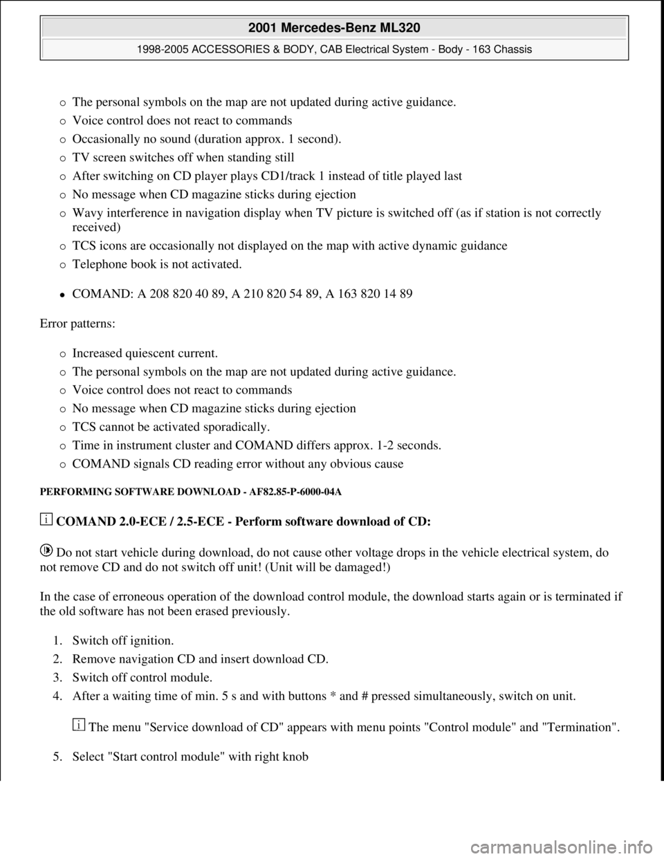
The personal symbols on the map are not updated during active guidance.
Voice control does not react to commands
Occasionally no sound (duration approx. 1 second).
TV screen switches off when standing still
After switching on CD player plays CD1/track 1 instead of title played last
No message when CD magazine sticks during ejection
Wavy interference in navigation display when TV picture is switched off (as if station is not correctly
received)
TCS icons are occasionally not displayed on the map with active dynamic guidance
Telephone book is not activated.
COMAND: A 208 820 40 89, A 210 820 54 89, A 163 820 14 89
Error patterns:
Increased quiescent current.
The personal symbols on the map are not updated during active guidance.
Voice control does not react to commands
No message when CD magazine sticks during ejection
TCS cannot be activated sporadically.
Time in instrument cluster and COMAND differs approx. 1-2 seconds.
COMAND signals CD reading error without any obvious cause
PERFORMING SOFTWARE DOWNLOAD - AF82.85-P-6000-04A
COMAND 2.0-ECE / 2.5-ECE - Perform software download of CD:
Do not start vehicle during download, do not cause other voltage drops in the vehicle electrical system, do
not remove CD and do not switch off unit! (Unit will be damaged!)
In the case of erroneous operation of the download control module, the download starts again or is terminated if
the old software has not been erased previously.
1. Switch off ignition.
2. Remove navigation CD and insert download CD.
3. Switch off control module.
4. After a waiting time of min. 5 s and with buttons * and # pressed simultaneously, switch on unit.
The menu "Service download of CD" appears with menu points "Control module" and "Termination".
5. Select "Start control module" with right knob
2001 Mercedes-Benz ML320
1998-2005 ACCESSORIES & BODY, CAB Electrical System - Body - 163 Chassis
me
Saturday, October 02, 2010 3:30:07 PMPage 181 © 2006 Mitchell Repair Information Company, LLC.
Page 1684 of 4133
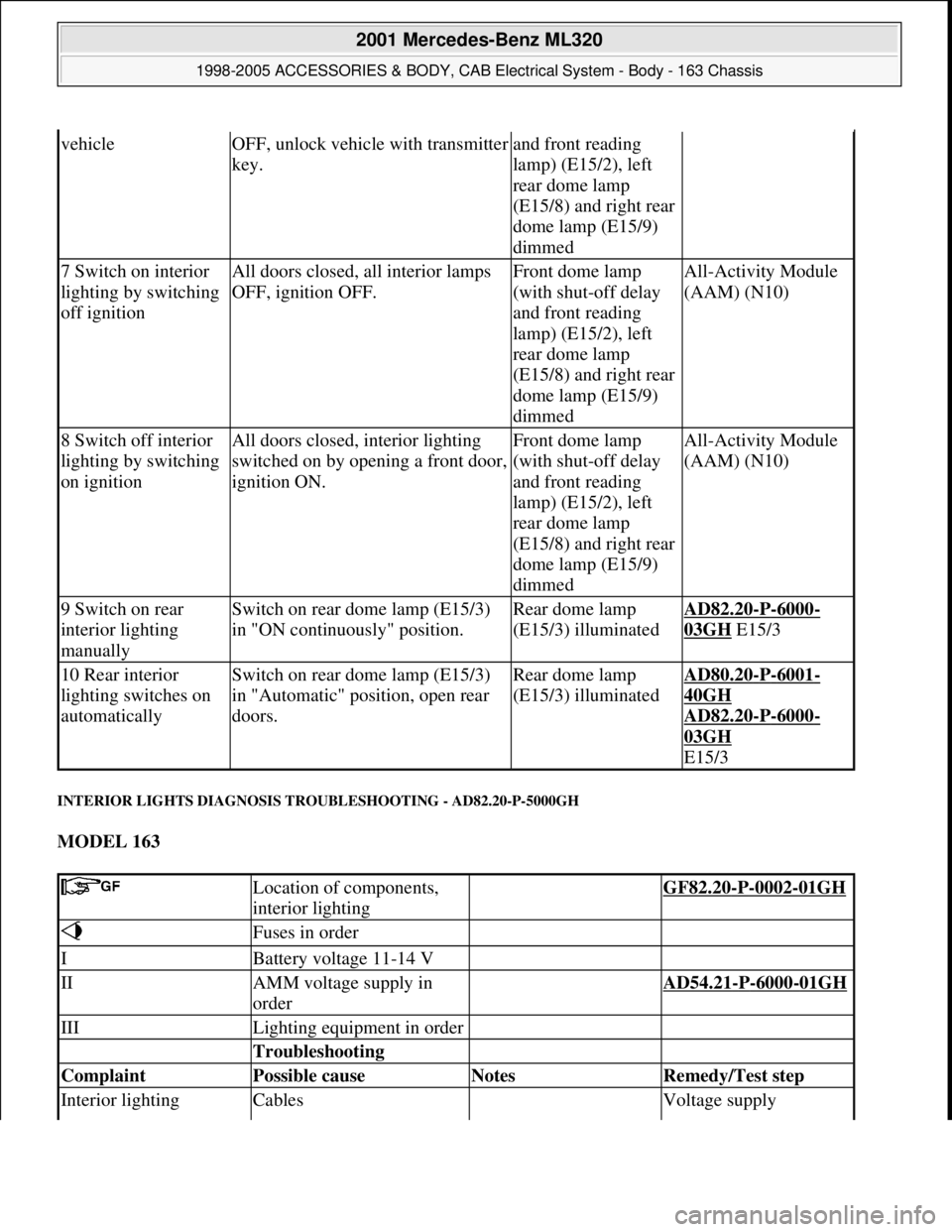
INTERIOR LIGHTS DIAGNOSIS TROUBLESHOOTING - AD82.20-P-5000GH
MODEL 163
vehicleOFF, unlock vehicle with transmitter
key.and front reading
lamp) (E15/2), left
rear dome lamp
(E15/8) and right rear
dome lamp (E15/9)
dimmed
7 Switch on interior
lighting by switching
off ignitionAll doors closed, all interior lamps
OFF, ignition OFF.Front dome lamp
(with shut-off delay
and front reading
lamp) (E15/2), left
rear dome lamp
(E15/8) and right rear
dome lamp (E15/9)
dimmedAll-Activity Module
(AAM) (N10)
8 Switch off interior
lighting by switching
on ignitionAll doors closed, interior lighting
switched on by opening a front door,
ignition ON.Front dome lamp
(with shut-off delay
and front reading
lamp) (E15/2), left
rear dome lamp
(E15/8) and right rear
dome lamp (E15/9)
dimmedAll-Activity Module
(AAM) (N10)
9 Switch on rear
interior lighting
manuallySwitch on rear dome lamp (E15/3)
in "ON continuously" position.Rear dome lamp
(E15/3) illuminatedAD82.20-P-6000-
03GH E15/3
10 Rear interior
lighting switches on
automaticallySwitch on rear dome lamp (E15/3)
in "Automatic" position, open rear
doors.Rear dome lamp
(E15/3) illuminatedAD80.20-P-6001-
40GH
AD82.20
-P-6000-
03GH
E15/3
Location of components,
interior lighting GF82.20-P-0002-01GH
Fuses in order
IBattery voltage 11-14 V
IIAMM voltage supply in
order AD54.21-P-6000-01GH
IIILighting equipment in order
Troubleshooting
Complaint Possible cause Notes Remedy/Test step
Interior lighting Cables Voltage supply
2001 Mercedes-Benz ML320
1998-2005 ACCESSORIES & BODY, CAB Electrical System - Body - 163 Chassis
me
Saturday, October 02, 2010 3:30:07 PMPage 189 © 2006 Mitchell Repair Information Company, LLC.
Page 1685 of 4133
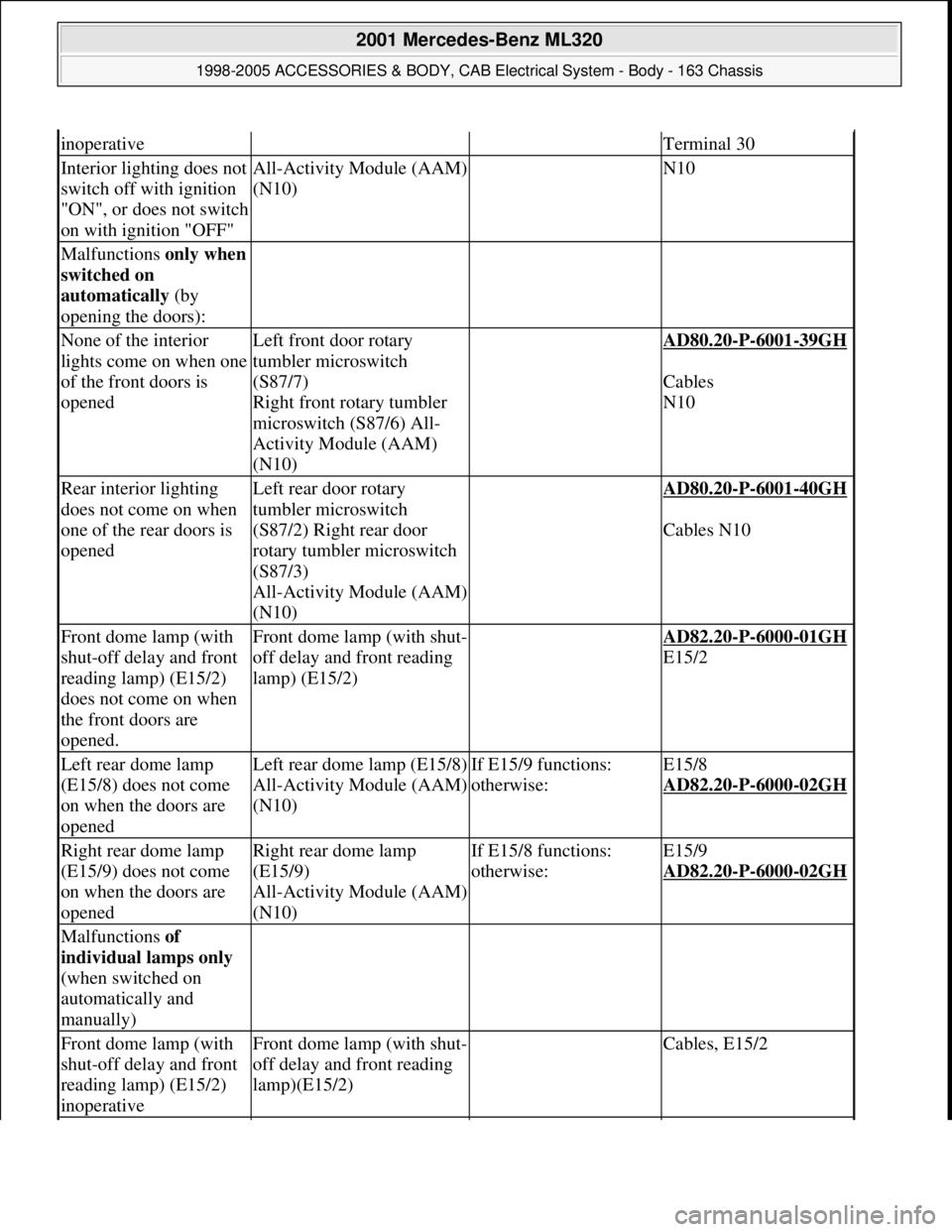
inoperativeTerminal 30
Interior lighting does not
switch off with ignition
"ON", or does not switch
on with ignition "OFF"All-Activity Module (AAM)
(N10) N10
Malfunctions only when
switched on
automatically (by
opening the doors):
None of the interior
lights come on when one
of the front doors is
openedLeft front door rotary
tumbler microswitch
(S87/7)
Right front rotary tumbler
microswitch (S87/6) All-
Activity Module (AAM)
(N10) AD80.20-P-6001-39GH
Cables
N10
Rear interior lighting
does not come on when
one of the rear doors is
openedLeft rear door rotary
tumbler microswitch
(S87/2) Right rear door
rotary tumbler microswitch
(S87/3)
All-Activity Module (AAM)
(N10) AD80.20-P-6001-40GH
Cables N10
Front dome lamp (with
shut-off delay and front
reading lamp) (E15/2)
does not come on when
the front doors are
opened.Front dome lamp (with shut-
off delay and front reading
lamp) (E15/2) AD82.20-P-6000-01GH
E15/2
Left rear dome lamp
(E15/8) does not come
on when the doors are
openedLeft rear dome lamp (E15/8)
All-Activity Module (AAM)
(N10)If E15/9 functions:
otherwise:E15/8
AD82.20
-P-6000-02GH
Right rear dome lamp
(E15/9) does not come
on when the doors are
openedRight rear dome lamp
(E15/9)
All-Activity Module (AAM)
(N10)If E15/8 functions:
otherwise:E15/9
AD82.20
-P-6000-02GH
Malfunctions of
individual lamps only
(when switched on
automatically and
manually)
Front dome lamp (with
shut-off delay and front
reading lamp) (E15/2)
inoperativeFront dome lamp (with shut-
off delay and front reading
lamp)(E15/2) Cables, E15/2
2001 Mercedes-Benz ML320
1998-2005 ACCESSORIES & BODY, CAB Electrical System - Body - 163 Chassis
me
Saturday, October 02, 2010 3:30:07 PMPage 190 © 2006 Mitchell Repair Information Company, LLC.
Page 1688 of 4133
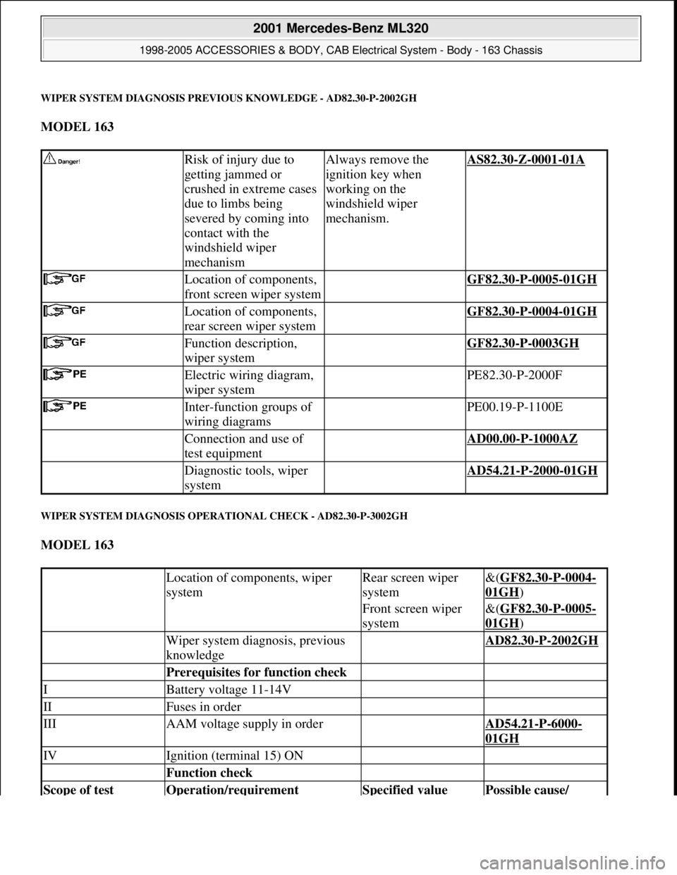
WIPER SYSTEM DIAGNOSIS PREVIOUS KNOWLEDGE - AD82.30-P-2002GH
MODEL 163
WIPER SYSTEM DIAGNOSIS OPERATIONAL CHECK - AD82.30-P-3002GH
MODEL 163
Risk of injury due to
getting jammed or
crushed in extreme cases
due to limbs being
severed by coming into
contact with the
windshield wiper
mechanismAlways remove the
ignition key when
working on the
windshield wiper
mechanism.AS82.30-Z-0001-01A
Location of components,
front screen wiper system GF82.30-P-0005-01GH
Location of components,
rear screen wiper system GF82.30-P-0004-01GH
Function description,
wiper system GF82.30-P-0003GH
Electric wiring diagram,
wiper system PE82.30-P-2000F
Inter-function groups of
wiring diagrams PE00.19-P-1100E
Connection and use of
test equipment AD00.00-P-1000AZ
Diagnostic tools, wiper
system AD54.21-P-2000-01GH
Location of components, wiper
systemRear screen wiper
system&(GF82.30-P-0004-
01GH)
Front screen wiper
system&(GF82.30-P-0005-
01GH)
Wiper system diagnosis, previous
knowledge AD82.30-P-2002GH
Prerequisites for function check
IBattery voltage 11-14V
IIFuses in order
IIIAAM voltage supply in order AD54.21-P-6000-
01GH
IVIgnition (terminal 15) ON
Function check
Scope of test Operation/requirement Specified value Possible cause/
2001 Mercedes-Benz ML320
1998-2005 ACCESSORIES & BODY, CAB Electrical System - Body - 163 Chassis
me
Saturday, October 02, 2010 3:30:07 PMPage 193 © 2006 Mitchell Repair Information Company, LLC.
Page 1695 of 4133
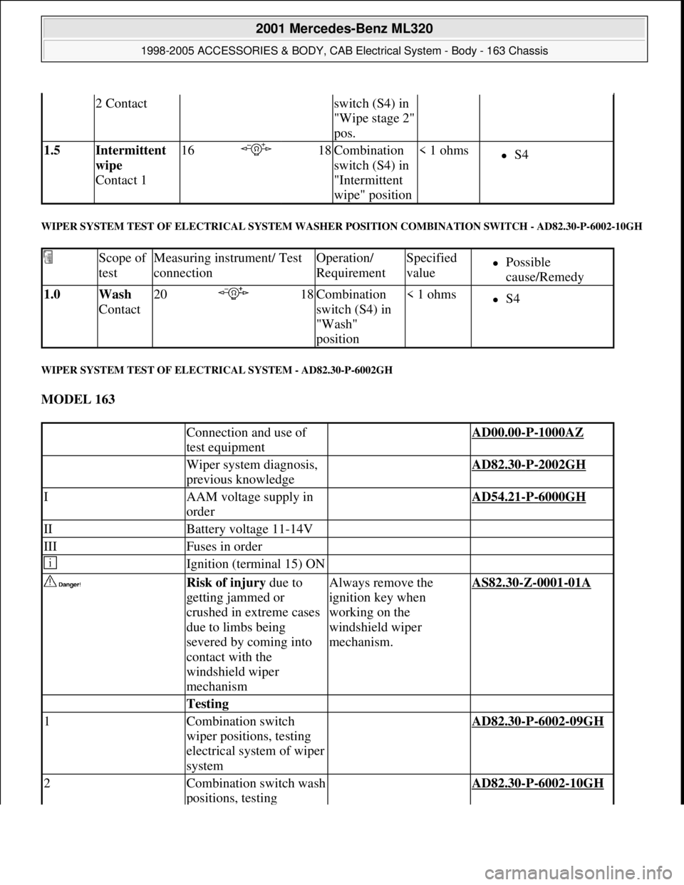
WIPER SYSTEM TEST OF ELECTRICAL SYSTEM WASHER POSITION COMBINATION SWITCH - AD82.30-P-6002-10GH
WIPER SYSTEM TEST OF ELECTRICAL SYSTEM - AD82.30-P-6002GH
MODEL 163
2 Contactswitch (S4) in
"Wipe stage 2"
pos.
1.5 Intermittent
wipe
Contact 116 18Combination
switch (S4) in
"Intermittent
wipe" position< 1 ohmsS4
Scope of
testMeasuring instrument/ Test
connectionOperation/
RequirementSpecified
valuePossible
cause/Remedy
1.0 Wash
Contact20 18Combination
switch (S4) in
"Wash"
position< 1 ohmsS4
Connection and use of
test equipment AD00.00-P-1000AZ
Wiper system diagnosis,
previous knowledge AD82.30-P-2002GH
IAAM voltage supply in
order AD54.21-P-6000GH
IIBattery voltage 11-14V
IIIFuses in order
Ignition (terminal 15) ON
Risk of injury due to
getting jammed or
crushed in extreme cases
due to limbs being
severed by coming into
contact with the
windshield wiper
mechanismAlways remove the
ignition key when
working on the
windshield wiper
mechanism.AS82.30-Z-0001-01A
Testing
1Combination switch
wiper positions, testing
electrical system of wiper
system AD82.30-P-6002-09GH
2Combination switch wash
positions, testing AD82.30-P-6002-10GH
2001 Mercedes-Benz ML320
1998-2005 ACCESSORIES & BODY, CAB Electrical System - Body - 163 Chassis
me
Saturday, October 02, 2010 3:30:07 PMPage 200 © 2006 Mitchell Repair Information Company, LLC.
Page 1704 of 4133
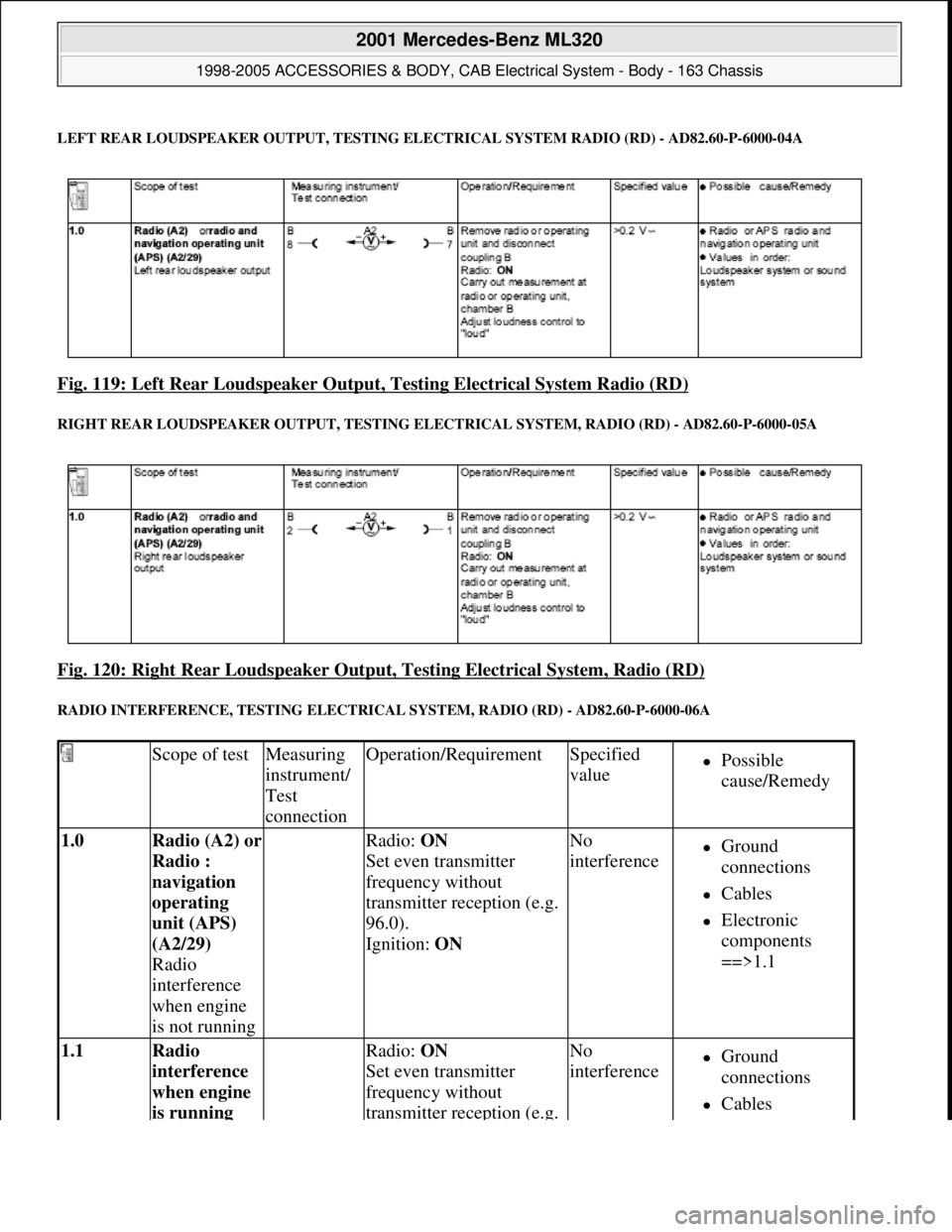
LEFT REAR LOUDSPEAKE R OUTPUT, TESTING ELEC TRICAL SYSTEM RADIO (RD) - AD82.60-P-6000-04A
Fig. 119: Left Rear Loudspeaker Output, Testing Electrical System Radio (RD)
RIGHT REAR LOUDSPEAKER OUTPUT, TESTING ELECTRICAL SYS TEM, RADIO (RD) - AD82.60-P-6000-05A
Fig. 120: Right Rear Loudspeaker Output , Testing Electrical System, Radio (RD)
RADIO INTERFERENCE, TESTING ELECTRICAL SYSTEM, RADIO (RD) - AD82.60-P-6000-06A
Scope of testMeasuring
instrument/
Test
connectionOperation/RequirementSpecified
valuePossible
cause/Remedy
1.0 Radio (A2) or
Radio :
navigation
operating
unit (APS)
(A2/29)
Radio
interference
when engine
is not running Radio: ON
Set even transmitter
frequency without
transmitter reception (e.g.
96.0).
Ignition: ON No
interferenceGround
connections
Cables
Electronic
components
==>1.1
1.1 Radio
interference
when engine
is running Radio: ON
Set even transmitter
frequency without
transmitter reception (e.g. No
interferenceGround
connections
Cables
2001 Mercedes-Benz ML320
1998-2005 ACCESSORIES & BODY, CAB Electr ical System - Body - 163 Chassis
me
Saturday, October 02, 2010 3:30:07 PMPage 209 © 2006 Mitchell Repair Information Company, LLC.
Page 1705 of 4133
RADIO RECEPTION, TESTING ELECTRICAL SYSTEM, RADIO (RD) - AD82.60-P-6000-07A
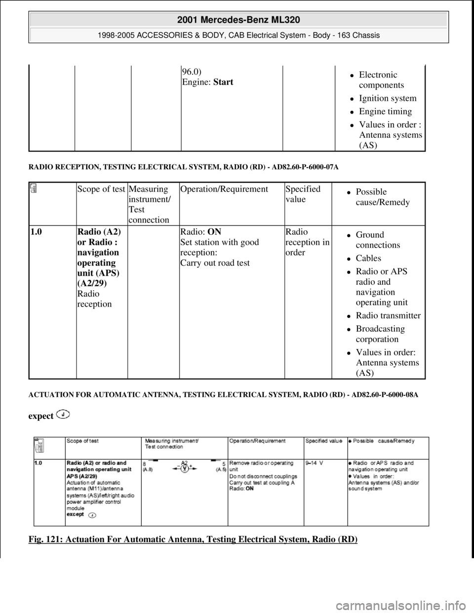
ACTUATION FOR AUTO MATIC ANTENNA, TESTING E LECTRICAL SYSTEM, RADIO (RD) - AD82.60-P-6000-08A
expect
Fig. 121: Actuation For Automatic Antenn a, Testing Electrical System, Radio (RD)
96.0)
Engine: Start Electronic
components
Ignition system
Engine timing
Values in order :
Antenna systems
(AS)
Scope of testMeasuring
instrument/
Test
connectionOperation/RequirementSpecified
valuePossible
cause/Remedy
1.0 Radio (A2)
or Radio :
navigation
operating
unit (APS)
(A2/29)
Radio
reception Radio: ON
Set station with good
reception:
Carry out road testRadio
reception in
orderGround
connections
Cables
Radio or APS
radio and
navigation
operating unit
Radio transmitter
Broadcasting
corporation
Values in order:
Antenna systems
(AS)
2001 Mercedes-Benz ML320
1998-2005 ACCESSORIES & BODY, CAB Electr ical System - Body - 163 Chassis
me
Saturday, October 02, 2010 3:30:07 PMPage 210 © 2006 Mitchell Repair Information Company, LLC.
Page 1711 of 4133
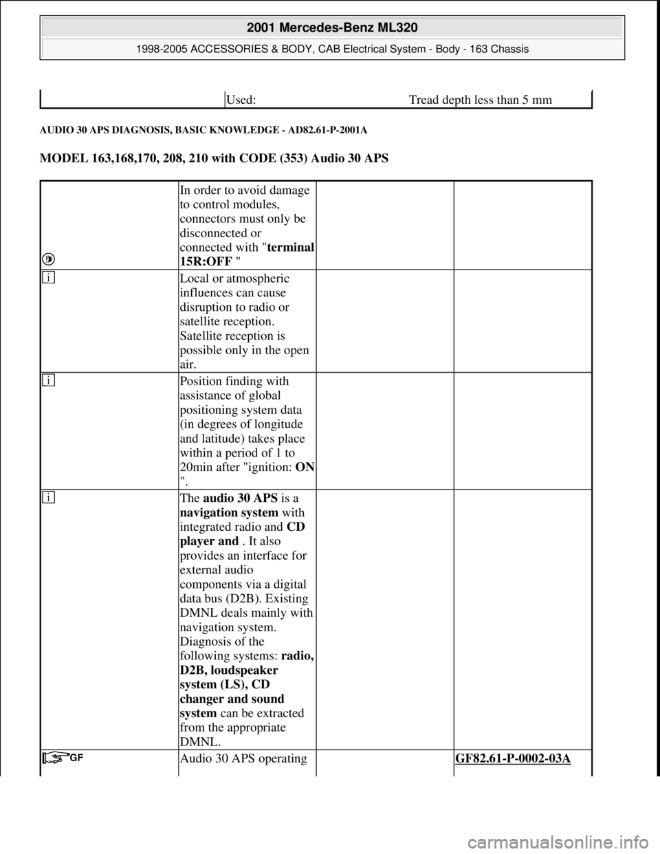
AUDIO 30 APS DIAGNOSIS, BASIC KNOWLEDGE - AD82.61-P-2001A
MODEL 163,168,170, 208, 210 with CODE (353) Audio 30 APS
Used:Tread depth less than 5 mm
In order to avoid damage
to control modules,
connectors must only be
disconnected or
connected with "terminal
15R:OFF "
Local or atmospheric
influences can cause
disruption to radio or
satellite reception.
Satellite reception is
possible only in the open
air.
Position finding with
assistance of global
positioning system data
(in degrees of longitude
and latitude) takes place
within a period of 1 to
20min after "ignition: ON
".
The audio 30 APS is a
navigation system with
integrated radio and CD
player and . It also
provides an interface for
external audio
components via a digital
data bus (D2B). Existing
DMNL deals mainly with
navigation system.
Diagnosis of the
following systems: radio,
D2B, loudspeaker
system (LS), CD
changer and sound
system can be extracted
from the appropriate
DMNL.
Audio 30 APS operating GF82.61-P-0002-03A
2001 Mercedes-Benz ML320
1998-2005 ACCESSORIES & BODY, CAB Electrical System - Body - 163 Chassis
me
Saturday, October 02, 2010 3:30:08 PMPage 216 © 2006 Mitchell Repair Information Company, LLC.