Page 1057 of 4133
253 Practical hints
What to do if …
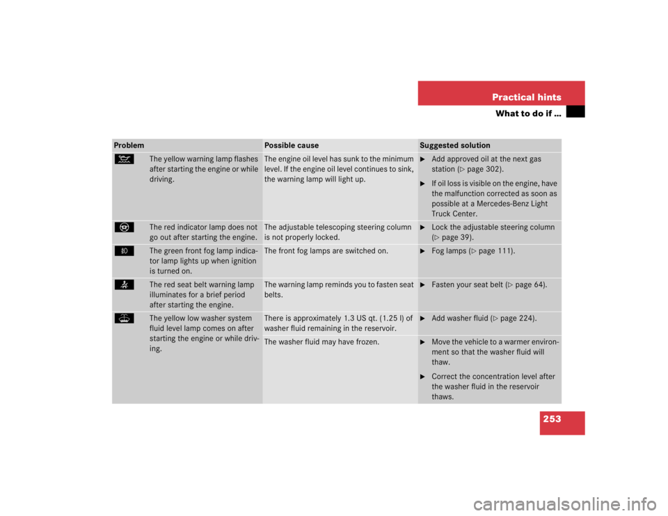
Problem
Possible cause
Suggested solution
:
The yellow warning lamp flashes
after starting the engine or while
driving.
The engine oil level has sunk to the minimum
level. If the engine oil level continues to sink,
the warning lamp will light up.
�
Add approved oil at the next gas
station (
�page 302).
�
If oil loss is visible on the engine, have
the malfunction corrected as soon as
possible at a Mercedes-Benz Light
Truck Center.
_
The red indicator lamp does not
go out after starting the engine.
The adjustable telescoping steering column
is not properly locked.
�
Lock the adjustable steering column
(�page 39).
‡
The green front fog lamp indica-
tor lamp lights up when ignition
is turned on.
The front fog lamps are switched on.
�
Fog lamps (
�page 111).
<
The red seat belt warning lamp
illuminates for a brief period
after starting the engine.
The warning lamp reminds you to fasten seat
belts.
�
Fasten your seat belt (
�page 64).
W
The yellow low washer system
fluid level lamp comes on after
starting the engine or while driv-
ing.
There is approximately 1.3 US qt. (1.25 l) of
washer fluid remaining in the reservoir.
�
Add washer fluid (
�page 224).
The washer fluid may have frozen.
�
Move the vehicle to a warmer environ-
ment so that the washer fluid will
thaw.
�
Correct the concentration level after
the washer fluid in the reservoir
thaws.
Page 1121 of 4133

317 Index
A
ABS 25, 76, 311
ABS control 76
LOW RANGE mode 77
Malfunction indicator lamp 242
Warning lamp 242
Accelerator position, automatic
transmission 123
Accident
In case of 52
Activating
Air circulation mode 139
Air recirculation mode 139
Anti-theft alarm system 83
Automatic climate control 135
ESP 82
Exterior headlamps 48
Hazard warning flasher 112
Headlamps 48
High beams 110
Ignition 33Immobilizer 54, 83
Rear passenger compartment ventila-
tion and climate control 141
Rear window defroster 133
Rear window wiper 51
Residual heat 140
Seat heater* 98
Tow-away alarm 85
Warning indicators (Parktronic*) 155
Windshield wipers 50
Activating automatic central locking 93
Adding
Coolant 223
Engine oil 221
Additional turn signals 266
Adjustable steering column
Indicator lamp 253
Adjusting 34
Backrest tilt 36, 38
Exterior rear view mirror 40
Head restraint height 36, 38Head restraint tilt 37, 39
Headlamp aim 272
Instrument cluster illumination 116
Manual seat 35
Mirrors 40
Power seats* 37
Seat cushion tilt 38
Seat fore and aft 35
Seat fore and aft adjustment 37
Seat height 36, 38
Seats 34
Steering wheel 39
Adjusting air distribution
Automatic climate control 137
Adjusting air volume
Automatic climate control 137
Air conditioner (cooling)
Turning on 139
Air conditioning
Cooling 139
Page 1131 of 4133

327 Index
I
Identification labels 292
Certification label 292
Vehicle identification number
(VIN) 292
Ignition 33
Immobilizer 83
Activating 54, 83
Deactivating 83
Indicator lamp
Adjustable steering column 253
Brake pad wear 254
Coolant 249
Front fog lamps 253
Low engine oil level 253
Indicators, additional
Speedometer display 256
Infant and child restraint systems 68
Installing 71
LATCH child seat mounts 72Information
About service and warranty 10
Button for Tele Aid* 177
Inside rear view mirror
Antiglare 126
Installing
Infant and child restraint systems 71
Wiper blades 273
Instrument cluster 24, 116, 313
Cleaning 238
Coolant temperature gauge 117
Display in the speedometer 117
Illumination 116
Lamps in 252
Outside temperature indicator 118
Instruments and controls see Cockpit 22
Integrated remote control
Erasing memory 185
Operating 185
Interior lighting 112Activating automatic control 113
Deactivating automatic control 113
Manual operation 113
Reading lamps 114
Interior storage spaces 164
Armrest 165
Cup holder 167
Glove box 164
Storage compartment in front of
armrest 165
Storage compartment under front pas-
senger seat* 164
Intermittent wiping 130
J
Jack 258
Jump starting 281
Page 1151 of 4133
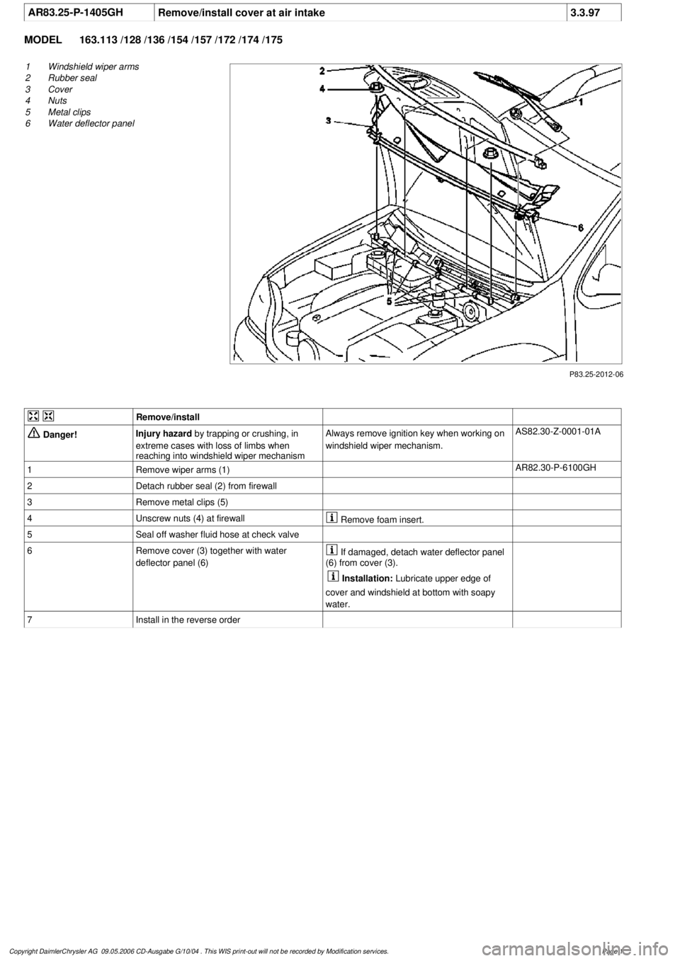
AR83.25-P-1405GH
Remove/install cover at air intake
3.3.97
MODEL
163.113 /128 /136 /154 /157 /172 /174 /175
P83.25-2012-06
1
Windshield wiper arms
2
Rubber seal
3
Cover
4
Nuts
5
Metal clips
6
Water deflector panel
Remove/install
Danger!
Injury hazard
by trapping or crushing, in
extreme cases with loss of limbs when
reaching into windshield wiper mechanism
Always remove ignition key when working on
windshield wiper mechanism.
AS82.30-Z-0001-01A
1
Remove wiper arms (1)
AR82.30-P-6100GH
2
Detach rubber seal (2) from firewall
3
Remove metal clips (5)
4
Unscrew nuts (4) at firewall
Remove foam insert.
5
Seal off washer fluid hose at check valve
6
Remove cover (3) together with water
deflector panel (6)
If damaged, detach water deflector panel
(6) from cover (3).
Installation:
Lubricate upper edge of
cover and windshield at bottom with soapy
water.
7
Install in the reverse order
Copyright DaimlerChrysler AG 09.05.2006 CD-Ausgabe G/10/04 . This WIS print-out will not be recorde
d by Modification services.
Page 1
Page 1162 of 4133
and skin caused
by contact with
fuel
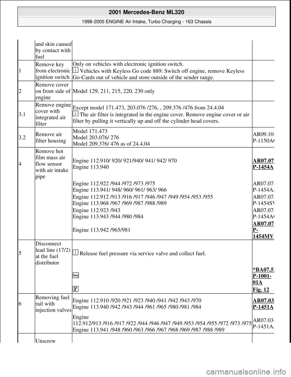
1
Remove key
from electronic
ignition switchOnly on vehicles with electronic ignition switch.
Vehicles with Keyless Go code 889: Switch off engine, remove Keyless
Go-Cards out of vehicle and store outside of the sender range.
2
Remove cover
on front side of
engine
Model 129, 211, 215, 220, 230 only
3.1
Remove engine
cover with
integrated air
filterExcept model 171.473, 203.076 /276, , 209.376 /476 from 24.4.04
The air filter is integrated in the engine cover. Remove engine cover or air
filter by pulling it vertically up and off the cylinder head covers.
3.2Remove air
filter housingModel 171.473
Model 203.076/ 276
Model 209.376/ 476 as of 24.4.04AR09.10-
P-1150AC
4
Remove hot
film mass air
flow sensor
with air intake
pipe
Engine 112.910/ 920/ 921/940/ 941/ 942/ 970
Engine 113.940AR07.07-
P-1454A
Engine 112.922 /944 /972 /973 /975
Engine 113.941/ 948/ 960/ 961/ 963/ 966AR07.07-
P-1454AA
Engine 112.912 /913 /916 /917 /946 /947 /949 /954 /953 /955
Engine 113.968 /967 /969 /987 /988 /989AR07.07-
P-1454SV
Engine 112.923 /943
Engine 113.943 /944 /980 /984AR07.07-
P-1454AG
Engine 113.942 /965/981
AR07.07-
P-
1454MV
5
Disconnect
lead line (17/2)
at the fuel
distributor
Release fuel pressure via service valve and collect fuel.
*BA07.52
P-1001-
01A
Fig. 12
6
Removing fuel
rail with
injection valvesEngine 112.910 /920 /921 /923 /940 /941 /942 /943 /970
Engine 113.940 /942 /943 /944 /961 /965 /980 /981 /984AR07.03-
P-1451A
Engine
112.912/913 /916 /917 /922 /944 /946 /947 /949 /953 /954 /955 /972 /973 /975
Engine 113.941 /948 /960 /963 /966 /967 /968 /969 /987 /988 /989AR07.03-
P-1451AA
Unscrew
2001 Mercedes-Benz ML320
1998-2005 ENGINE Air Intake, Turbo Charging - 163 Chassis
me
Saturday, October 02, 2010 3:16:57 PMPage 11 © 2006 Mitchell Repair Information Company, LLC.
Page 1167 of 4133
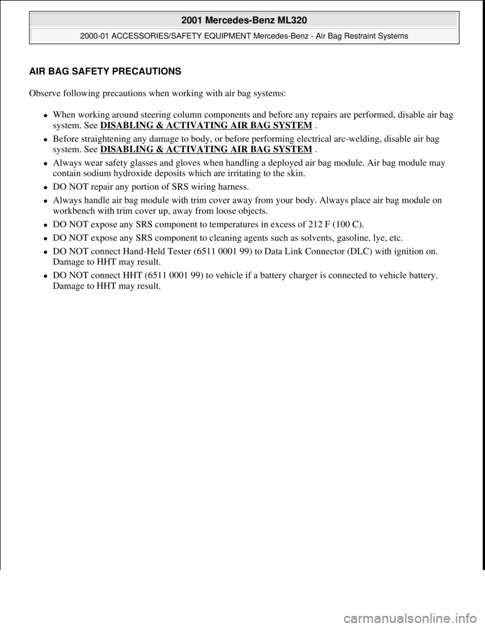
AIR BAG SAFETY PRECAUTIONS
Observe following precautions when working with air bag systems:
When working around steering column components and before any repairs are performed, disable air bag
system. See DISABLING & ACTIVATING AIR BAG SYSTEM
.
Before straightening any damage to body, or before performing electrical arc-welding, disable air bag
system. See DISABLING & ACTIVATING AIR BAG SYSTEM
.
Always wear safety glasses and gloves when handling a deployed air bag module. Air bag module may
contain sodium hydroxide deposits which are irritating to the skin.
DO NOT repair any portion of SRS wiring harness.
Always handle air bag module with trim cover away from your body. Always place air bag module on
workbench with trim cover up, away from loose objects.
DO NOT expose any SRS component to temperatures in excess of 212 F (100 C).
DO NOT expose any SRS component to cleaning agents such as solvents, gasoline, lye, etc.
DO NOT connect Hand-Held Tester (6511 0001 99) to Data Link Connector (DLC) with ignition on.
Damage to HHT may result.
DO NOT connect HHT (6511 0001 99) to vehicle if a battery charger is connected to vehicle battery.
Dama
ge to HHT may result.
2001 Mercedes-Benz ML320
2000-01 ACCESSORIES/SAFETY EQUIPMENT Mercedes-Benz - Air Bag Restraint Systems
2001 Mercedes-Benz ML320
2000-01 ACCESSORIES/SAFETY EQUIPMENT Mercedes-Benz - Air Bag Restraint Systems
me
Saturday, October 02, 2010 3:43:48 PMPage 1 © 2006 Mitchell Repair Information Company, LLC.
me
Saturday, October 02, 2010 3:43:51 PMPage 1 © 2006 Mitchell Repair Information Company, LLC.
Page 1192 of 4133
Kick-Down, Function
See KICK
-DOWN FUNCTION (UP TO 5/31/02).
Hydropneumatic Transmission Control, Function
See HYDROPNEUMATIC TRANSMISSION CONTROL, FUNCTION
.
Shift-Lock, Function
See SHIFT
-LOCK FUNCTION.
Function Of Locking Of Selector Lever Position "P"
See FUNCTION OF LOCKING OF SELECTOR LEVER POSITION "P"
.
Ignition Lock Locking, Function
See IGNITION LOCK INTERLOCK
.
Function Of Shift Lock Override
See FUNCTION OF SHIFT LOCK OVERRIDE
.
Survey Of System Components, Automatic Transmission, Location/Task/Design/Function
See SURVEY OF SYSTEM COMPONENTS, AUTOMATIC TRANSMISSION,
LOCATION/TASK/DESIGN/FUNCTION.
Shift From 1 To 2, Function
2001 Mercedes-Benz ML320
1998-03 AUTOMATIC TRANSMISSIONS Complete Transmissions - ML 320 - 722.662
me
Saturday, October 02, 2010 3:15:25 PMPage 23 © 2006 Mitchell Repair Information Company, LLC.
Page 1205 of 4133
If the parking lock is engaged, the ignition key has been removed and the service brake is not activated, the
locking pawl (39) blocks the detent plate (38). See Fig. 19
. The park pawl cannot be released. The park pawl
can only be released by turning the ignition key to position "1" and pressing the brake pedal. Starting from
ignition key position "1" the locking cam (61) in the steering lock releases the control cable (53). When the
brake pedal is depressed, the lock lever (55) and roller (58) are twisted down, the return spring at the brake
pedal (57) is tensionsed and the release lever (56) is released.
The force of the pressure spring (64) is now applied via the cables (53, 54) against the lesser force of the
pressure spring (62) and pulls the locking valve (60) in front of the contour of the locking cam (61). The locking
pawl (39) is simultaneously turned via the link rod and lifts up off the detent plate (38).
The parking lock can now be released.
The design of the parking lock interlock is the same as for the steering lock interlock and it functions with
reciprocal action to the steering lock interlock.
Steering Lock Interlock, Function
2001 Mercedes-Benz ML320
1998-03 AUTOMATIC TRANSMISSIONS Complete Transmissions - ML 320 - 722.662
me
Saturday, October 02, 2010 3:15:26 PMPage 36 © 2006 Mitchell Repair Information Company, LLC.