Page 950 of 4133
146 Controls in detailPower windowsSynchronizing power windows
The power window must be resynchroni-
zed each time�
after the battery has been discon-
nected.
�
if the power windows cannot be fully
opened (Express-open) or closed (Ex-
press-close).
Synchronizing the power windows
�
Switch on ignition.
�
Press the power window switches at
the symbolj until the side win-
dows are closed.
Hold the switches for approximately
one second.
The power window are synchronized.
Rear quarter windows*
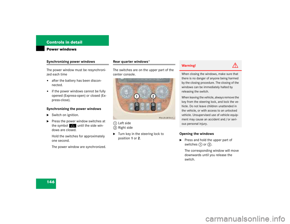
The switches are on the upper part of the
center console.
1Left side
2Right side�
Turn key in the steering lock to
position1 or2.Opening the windows
�
Press and hold the upper part of
switches1 or2.
The corresponding window will move
downwards until you release the
switch.Warning!
G
When closing the windows, make sure that
there is no danger of anyone being harmed
by the closing procedure. The closing of the
windows can be immediately halted by
releasing the switch.
When leaving the vehicle, always remove the
key from the steering lock, and lock the ve-
hicle. Do not leave children unattended in
the vehicle, or with access to an unlocked
vehicle. Unsupervised use of vehicle equip-
ment may cause an accident and / or seri-
ous personal injury.
Page 953 of 4133
149 Controls in detail
Sliding / pop-up roof*
�
Turn the key in the steering lock to
position1 or2 (
�page 33).
Opening and closing the
sliding / pop-up roof
�
To open, close, raise or lower the
sliding / pop-up roof, move the switch
in the required direction1to4.
Release the switch when the roof has
reached the desired position.
Raising the roof
�
Press and hold the switch in
direction1.
The roof is raised at rear.
Lowering the roof
�
Pull and hold the switch in direction3.
The sliding / pop-up roof is lowered and
closed.Opening the sliding / pop-up roof auto-
matically
�
Briefly press switch in direction2.
The sliding / pop up roof will not open
completely.
�
Press switch again to open the
sliding / pop-up roof completely.
Stopping the roof
�
Briefly press the switch in any direc-
tion.
The movement of the roof will stop.
Synchronizing the sliding / pop-up roof
The power sliding / pop-up roof must be re-
synchronized each time after:�
the battery has been disconnected
�
the sliding / pop-up roof has been
closed manually
�
the sliding / pop-up roof does not open
smoothly
�
a malfunction
Synchronizing
�
Remove the fuse from the fuse box
(�page 287).
�
Replace the fuse in the fuse box.
�
Switch on ignition.
�
Press and hold the switch in
direction1 until the sliding / pop-up
roof is fully raised at the rear.
Hold the switch for approximately one
second.
The sliding / pop-up roof is synchro-
nized.
Page 957 of 4133

153 Controls in detail
Driving systems
Parktronic system* (Parking assist)
The Parktronic system assists the driver
during parking maneuvers. It visually and
audibly indicates the distance between the
vehicle and an obstacle.
With the ignition on, the Parktronic system
engages automatically at speeds up to ap-
proximately 10 mph (15 km / h) and deac-
tivates during higher speeds.Parktronic system monitors your vehicle’s
environment by means of six sensors in
the front bumper and four sensors in the
rear bumper.
1Sensors located in front bumperWarning!
G
Parktronic is a supplemental system. It is
not intended to nor does it replace the need
for extreme care. The responsibility during
parking and other critical maneuvers rests
always with the driver.
Make sure that no persons or animals are lo-
cated in the area in which your are maneu-
vering. They could otherwise be injured.
Special attention must be paid to objects
with smooth surfaces or low silhouettes
(e.g. trailer couplings, painted posts, or
street curbs). Such objects may not be de-
tected by the system and can damage the
vehicle.
The operational function of the Parktronic
system can be affected by dirty sensors, es-
pecially at times of snow and ice. For notes
on cleaning the Parktronic system sensors
(�page 237).
Interference caused by other ultrasonic sig-
nals (e.g. working jackhammers or the air
brakes of trucks) can cause the system to
send erratic indications, and should be tak-
en into consideration.
Page 959 of 4133
155 Controls in detail
Driving systems
Warning indicators
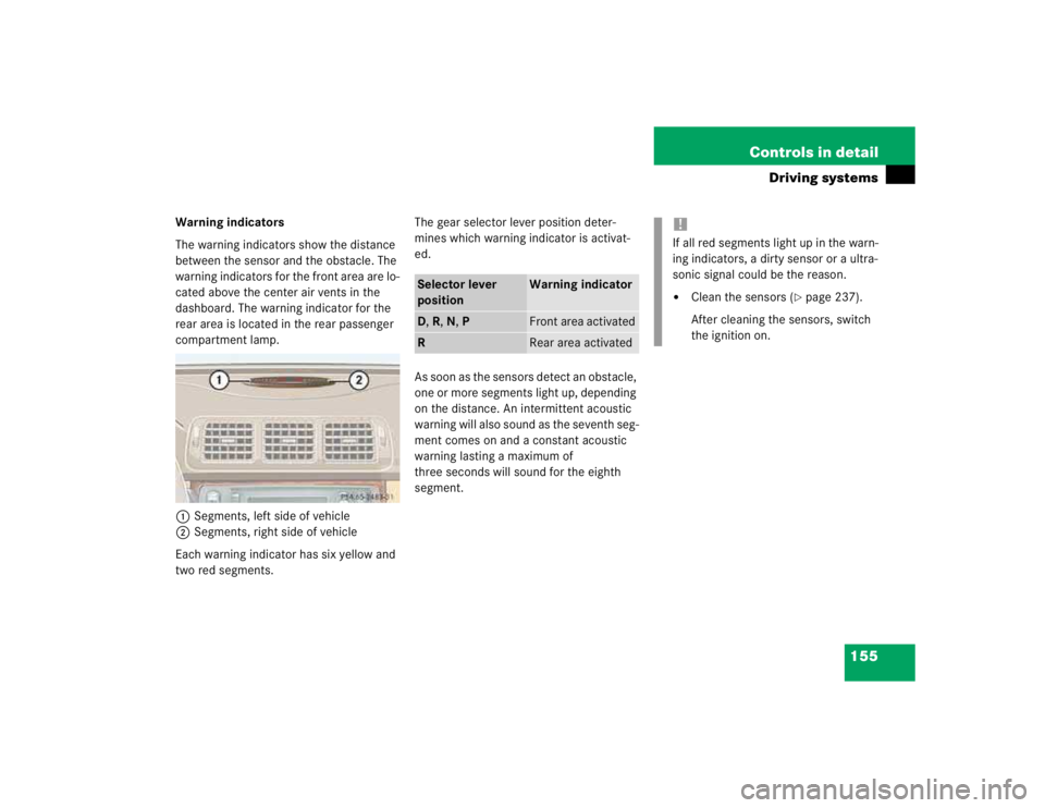
The warning indicators show the distance
between the sensor and the obstacle. The
warning indicators for the front area are lo-
cated above the center air vents in the
dashboard. The warning indicator for the
rear area is located in the rear passenger
compartment lamp.
1Segments, left side of vehicle
2Segments, right side of vehicle
Each warning indicator has six yellow and
two red segments.The gear selector lever position deter-
mines which warning indicator is activat-
ed.
As soon as the sensors detect an obstacle,
one or more segments light up, depending
on the distance. An intermittent acoustic
warning will also sound as the seventh seg-
ment comes on and a constant acoustic
warning lasting a maximum of
three seconds will sound for the eighth
segment.
Selector lever
position
Warning indicator
D, R, N, P
Front area activated
R
Rear area activated
!If all red segments light up in the warn-
ing indicators, a dirty sensor or a ultra-
sonic signal could be the reason.�
Clean the sensors (
�page 237).
After cleaning the sensors, switch
the ignition on.
Page 960 of 4133
156 Controls in detailDriving systemsSwitching Parktronic system on / off
You can switch Parktronic system off
manually.
The switch is located on the lower part of
the center console.
1Parktronic off
2Indicator lamp
3Parktronic onSwitching Parktronic off
�
Press switch on the upper part1.
Indicator lamp2 comes on.
Switching Parktronic on
�
Press switch on the upper part3.
The indicator lamp2 goes out.!If the Parktronic system is malfunction-
ing, all red segments of the warning in-
dicators light up and an additional
warning sounds.
Contact your Mercedes-Benz Light
Truck Center as soon as possible.
iIf you switch the ignition on, the
Parktronic system will be automatically
switched on.
The rear Parktronic sensors will not au-
tomatically disengage when towing a
trailer. Therefore switch the Parktronic
system off.
Page 973 of 4133
169 Controls in detail
Useful features
Cigarette lighter�
Switch on the ignition.
�
Push in cigarette lighter2
(�page 168).
The cigarette lighter will pop out auto-
matically when hot.
Ashtray and cigarette lighter in the rear
center console
1Ashtray
2Cigarette lighter
3Cover plate
Opening the ashtray
�
Briefly touch cover plate3.
The ashtray opens automatically.
Removing ashtray insert
�
Grip the insert on the sides and pull it
out upwards.Reinstalling ashtray insert
�
Install ashtray insert.
�
Close the ashtray.
Cigarette lighter
�
Switch on the ignition.
�
Push in cigarette lighter2.
The cigarette lighter will pop out auto-
matically when hot.
!Close the ashtray in the rear center
console before folding the rear seat
bench.
Page 974 of 4133
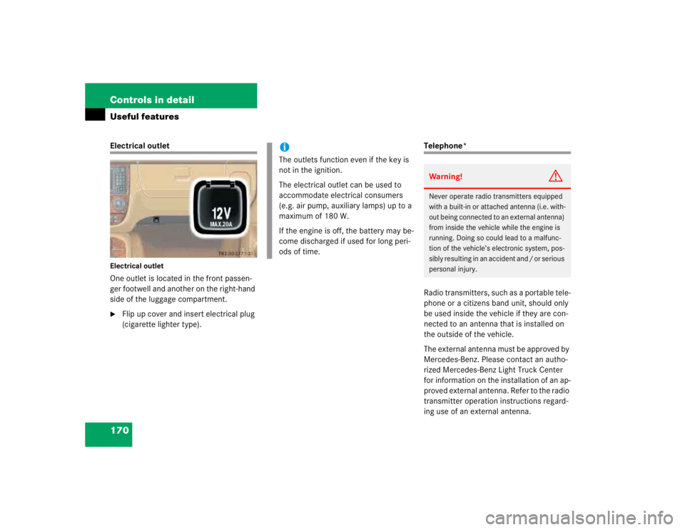
170 Controls in detailUseful featuresElectrical outletElectrical outletOne outlet is located in the front passen-
ger footwell and another on the right-hand
side of the luggage compartment.�
Flip up cover and insert electrical plug
(cigarette lighter type).
Telephone*
Radio transmitters, such as a portable tele-
phone or a citizens band unit, should only
be used inside the vehicle if they are con-
nected to an antenna that is installed on
the outside of the vehicle.
The external antenna must be approved by
Mercedes-Benz. Please contact an autho-
rized Mercedes-Benz Light Truck Center
for information on the installation of an ap-
proved external antenna. Refer to the radio
transmitter operation instructions regard-
ing use of an external antenna.
iThe outlets function even if the key is
not in the ignition.
The electrical outlet can be used to
accommodate electrical consumers
(e.g. air pump, auxiliary lamps) up to a
maximum of 180 W.
If the engine is off, the battery may be-
come discharged if used for long peri-
ods of time.
Warning!
G
Never operate radio transmitters equipped
with a built-in or attached antenna (i.e. with-
out being connected to an external antenna)
from inside the vehicle while the engine is
running. Doing so could lead to a malfunc-
tion of the vehicle’s electronic system, pos-
sibly resulting in an accident and / or serious
personal injury.
Page 986 of 4133
182 Controls in detailUseful features
Programming or reprogramming the in-
tegrated remote control
Step 1:�
Switch on ignition.
Step 2:
�
If you have previously programmed an
integrated signal transmitter button
and wish to retain its programming,
proceed to step 3. Otherwise, press
and hold the two outer signal transmit-
ter buttons3 and5 and release
them only when the indicator light be-
gins to flash after approximately 20
seconds (do not hold the button for
longer than 30 seconds). This proce-
dure erases any previous settings for
all three channels and initializes the
memory. If you later wish to program a
second and / or third hand-held trans-
mitter to the remaining two signal
transmitter buttons, do not repeat this
step and begin directly with step 3.Step 3:
�
Hold the end of the hand-held remote
control transmitter1 of the device
you wish to train approximately 2 to
5 in (5 to12 cm) away from the surface
of the integrated remote control locat-
ed on the interior rear view mirror,
keeping the indicator lamp6 in view.
Step 4:
�
Using both hands, simultaneously
press the hand-held transmitter
button2 and the desired integrated
signal transmitter button (3, 4
or5). Do not release the buttons until
completing step 5.
The indicator lamp6 on the integrat-
ed remote control will flash, first slowly
and then rapidly.
iFor operation in the USA only:
This device complies with Part 15 of
the FCC Rules. Operation is subject to
the following two conditions:
(1) This device may not cause harmful
interference, and
(2) this device must accept any inter-
ference received, including interfer-
ence that may cause undesired
operation.
Any unauthorized modification to this
device could void the user’s authority
to operate the equipment.