Page 1207 of 4133
Operation
The steering lock interlock prevents the ignition key being removed when the parking lock is not engaged.
The locking pawl (39) is positioned on the exterior contour of the detent plate (38) if the parking lock is not
engaged and if the brake pedal is not depressed. See Fig. 20
.
The cables (53, 54) hold the locking valve (60) in its position in front of the locking cam (61) against the force
of the pressure spring. Therefore, the ignition key cannot be turned to the "0" position.
In selector lever position "P" and with the brake pedal in the rest position, the force of the return spring (57) can
pull the locking pawl (39) under the stop at the detent plate (38) and the pressure spring (62) simultaneously
pulls the locking valve (60) away from the locking cam (61).
The ignition key can now be turned to the "0" position and removed from the ignition.
The design of the parking lock interlock is the same as for the steering lock interlock and it functions with
reciprocal action to the steering lock interlock.
Parking Lock, Location/Task/Design/Function
See PARKING LOCK, LOCATION/TASK/DESIGN/FUNCTION
.
Parking Lock, Location/Task/Design/Function
2001 Mercedes-Benz ML320
1998-03 AUTOMATIC TRANSMISSIONS Complete Transmissions - ML 320 - 722.662
me
Saturday, October 02, 2010 3:15:26 PMPage 38 © 2006 Mitchell Repair Information Company, LLC.
Page 1405 of 4133
See MODULATING PRESSURE, FUNCTION
.
Shift Valve Pressure, Function
See SHIFT VALVE PRESSURE, FUNCTION
.
Lubricating Pressure, Function
See LUBRICATING PRESSURE, FUNCTION
.
Regulating Valve Pressure, Function
See REGULATING VALVE PRESSURE, FUNCTION
.
Limp-Home Mode, Function
Operation
In order to ensure a safe driving state and to prevent damage to the automatic transmission, the ECT control
module (N15/3) switches to limp-home mode in the event of critical faults. A fault code assigned to the fault is
stored in memory.
All solenoid and regulating valves are thus de-energized.
Effect
The gear last engaged remains engaged.
The modulating pressure and shift pressure rise to the maximum levels.
The torque converter lockup clutch is switched off.
In order to preserve the operability of the vehicle to some extent, the hydraulic control can be used to engage
2nd gear or reverse:
Stop Vehicle
Switch Off Engine
Move Selector Lever To "P"
Wait At Least 10 Seconds
Start Engine
Move Selector Lever To "D": 2Nd Gear
Move Selector Lever To "R"
The limp-home function remains active until the fault is rectified or the stored fault code is erased. Sporadic
faults can be reset via ignition OFF/ON.
2001 Mercedes-Benz ML320
1998-03 AUTOMATIC TRANSMISSIONS Complete Transmissions - ML 320 - 722.662
me
Saturday, October 02, 2010 3:15:29 PMPage 236 © 2006 Mitchell Repair Information Company, LLC.
Page 1457 of 4133
When the kick-down switch (S16/6) is operated via the accelerator pedal a signal is passed on to the ETC
control module (N15/3). Based on this information the ETC control module (N15/3) actuates the solenoid
valves so that the upshifts and downshifts take place at higher engine speed.
Shift-Lock Function
Operation
The term shift lock combines the functions which, in addition to the parking brake, offer an additional safeguard
for the vehicle to prevent it moving off unintentionally.
These include the functions of locking the selector lever position "P" and locking the ignition lock as well as the
parking lock in the transmission.
The shift lock function only allows shifting out of selector lever position "P" if the transmitter key (A8/1) has
been turned into the position "Ignition: ON" and the brake pedal is depressed.
In order to ensure that after parking the vehicle the selector lever is shifted into selector lever position "P", the
transmitter key (A8/1) can only be turned towards "0" in this position and removed from the EZS control
module (N73) (ignition lock locking, function).
The vehicle is secured mechanically by blocking the park pawl gear.
In the event of mechanical or electrical/electronic faults it is possible to unlock selector lever position "P"
manually (shift lock override function).
Function Of Locking Of Selector Lever Position "P"
See FUNCTION OF LOCKING OF SELECTOR LEVER POSITION "P"
.
Ignition Lock Locking, Function
See IGNITION LOCK INTERLOCK
.
Function Of Shift Lock Override
See FUNCTION OF SHIFT LOCK OVERRIDE
.
Function Of Locking Of Selector Lever Position "P" (With Touch Shift)
Operation
2001 Mercedes-Benz ML320
1998-03 AUTOMATIC TRANSMISSIONS Complete Transmissions - ML 320 - 722.662
me
Saturday, October 02, 2010 3:15:30 PMPage 288 © 2006 Mitchell Repair Information Company, LLC.
Page 1459 of 4133
ignition key position Ignition "ON" when the brake pedal is depressed and therefore when the brake lamp
switch (S9/1) is actuated and when selector lever position "P" is recognized.
The R/P locking magnet (89) releases the selector lever thus allowing the selector lever to be moved away from
position "P".
Parking Lock, Location/Task/Design/Function - See PARK PAWL,
LOCATION/TASK/DESIGN/FUNCTION.
Ignition Lock Interlock
Operation
2001 Mercedes-Benz ML320
1998-03 AUTOMATIC TRANSMISSIONS Complete Transmissions - ML 320 - 722.662
me
Saturday, October 02, 2010 3:15:30 PMPage 290 © 2006 Mitchell Repair Information Company, LLC.
Page 1460 of 4133
Fig. 163: Ignition Lock Interlock
2001 Mercedes-Benz ML320
1998-03 AUTOMATIC TRANSMI SSIONS Complete Transmissions - ML 320 - 722.662
me
Saturday, October 02, 2010 3:15:30 PMPage 291 © 2006 Mitchell Repair Information Company, LLC.
Page 1461 of 4133
Courtesy of MERCEDES-BENZ OF NORTH AMERICA.
The mechanism of the ignition lock interlock connects the selector lever of the floor shift with the ETC control
module (N73). See Fig. 163
. It prevents the transmitter key (A8/1) from being withdrawn when the selector
lever is not at position "P".
When the parking lock is not engaged (selector lever position "D", "R", "N"), the locking valve (60) locks the
locking cam (61). The compression spring (62) only pulls the locking valve (60) away from the locking cam
(61) in selector lever position "P". The transmitter key (A8/1) can now be turned to position "0" and removed
from the ignition.
Parking Lock, Location/Task/Design/Function
See PARK PAWL, LOCATION/TASK/DESIGN/FUNCTION
.
Function Of Shift lock Override
Transmission with touch shift 722.6 in MODEL 163
Operation
2001 Mercedes-Benz ML320
1998-03 AUTOMATIC TRANSMISSIONS Complete Transmissions - ML 320 - 722.662
me
Saturday, October 02, 2010 3:15:30 PMPage 292 © 2006 Mitchell Repair Information Company, LLC.
Page 1473 of 4133
See OIL LEVEL CONTROL, FUNCTION
.
Function of Torque Converter Lockup Clutch Control
See FUNCTION OF TORQUE CONVERTER LOCKUP CLUTCH CONTROL
.
Torque Converter Lockup Clutch Control Pressure, Function
See TORQUE CONVERTER LOCKUP CLUTCH CONTROL PRESSURE, FUNCTION
.
Function Of Locking Of Selector Lever Position "P"
See FUNCTION OF LOCKING OF SELECTOR LEVER POSITION "P"
.
Ignition Lock Locking, Function
See IGNITION LOCK INTERLOCK
.
Function Of Shift Lock Override
See FUNCTION OF SHIFT LOCK OVERRIDE
.
Survey Of System Components, Automatic Transmission, Location/Task/Design/Function
See SURVEY OF SYSTEM COMPONENTS, AUTOMATIC TRANSMISSION,
LOCATION/TASK/DESIGN/FUNCTION.
2001 Mercedes-Benz ML320
1998-03 AUTOMATIC TRANSMISSIONS Complete Transmissions - ML 320 - 722.662
me
Saturday, October 02, 2010 3:15:30 PMPage 304 © 2006 Mitchell Repair Information Company, LLC.
Page 1489 of 4133
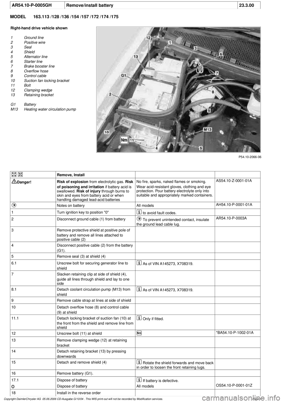
AR54.10-P-0005GH
Remove/install battery
23.3.00
MODEL
163.113 /128 /136 /154 /157 /172 /174 /175
P54.10-2066-06
Right-hand drive vehicle shown
1
Ground line
2
Positive wire
3
Seal
4
Shield
5
Alternator line
6
Starter line
7
Brake booster line
8
Overflow hose
9
Control cable
10
Suction fan locking bracket
11
Bolt
12
Clamping wedge
13
Retaining bracket
G1 Battery
M13
Heating water circulation pump
Remove, Install
Danger!
Risk of explosion
from electrolytic gas.
Risk
of poisoning and irritation
if battery acid is
swallowed.
Risk of injury
through burns to
skin and eyes from battery acid or when
handling damaged lead-acid batteries
No fire, sparks, naked flames or smoking.
Wear acid-resistant gloves, clothing and eye
protection. Pour battery electrolyte only into
suitable and appropriately marked containers.
AS54.10-Z-0001-01A
Notes on battery
All models
AH54.10-P-0001-01A
1
Turn ignition key to position "0"
to avoid fault codes.
2
Disconnect ground cable (1) from battery
To prevent unintended contact, insulate
the ground lead cable lug.
AR54.10-P-0003A
3
Remove protective shield at positive pole of
battery and remove all lines attached to
positive cable (2)
4
Disconnect positive cable (2) from the battery
(G1).
5
Remove seal (3) at shield (4)
6.1
Unscrew bolt for securing generator line to
shield
As of VIN A145273, X708319.
7
Slacken retaining clip at side of shield (4),
guide all lines through shield and lay to one
side
8.1
Detach coolant circulation pump (M13) from
shield
As of VIN A145273, X708319.
9
Remove cable strap at lines at side of shield
10
Detach overflow hose (8) and control cable
(9) at shield
11.1
Detach locking bracket of suction fan (10) at
the front from the shield and remove line from
shield
Only if fitted.
12
Unscrew bolt (11) at shield
*BA54.10-P-1002-01A
13
Remove clamping wedge (12) at retaining
bracket
14
Detach retaining bracket (13) by pressing
downwards
15
Detach and remove shield (4)
Rotate the shield forwards and move back
in order to loosen the front retaining lugs.
16
Remove battery (G1).
17.1
Dispose of battery
If battery is defective.
o
Dispose of battery
All models
OS54.10-P-0001-01Z
18
Install in the reverse order
Copyright DaimlerChrysler AG 05.06.2006 CD-Ausgabe G/10/04 . This WIS print-out will not be recorde
d by Modification services.
Page 1