1997 MERCEDES-BENZ ML430 ignition
[x] Cancel search: ignitionPage 378 of 4133
Disconnect passenger-side air bag module squib connector. Remove 4 passenger-side air bag module
mounting nuts.
2. To install, reverse removal proc edure. Ensure passenger-side air bag module squib connector audibly
clicks when connecting connector. Activate air bag system. Perform system operation check to ensure
system is functioning properly. See SYSTEM OPERATION CHECK
.
Removal & Installation (E Class)
1. Before proceeding, See AIR BAG SAFETY PRECAUTIONS . Disable air bag system. See
DISABLING & ACTIVATI NG AIR BAG SYSTEM
. Remove ignition key. Remove 2 central
mounting bolts for passenger-side air bag module. Li ft air bag module enough to unplug connector from
rear of module. Place module away fr om work area, with pad facing upward.
2. If necessary to replace passenger air bag instal lation frame, remove 4 frame mounting bolts. Remove
installation frame from vehicle.
3. To install air bag module or inst allation frame, reverse removal proc edure. Activate air bag system.
Perform system operation check to ensu re system is functioning properly. See SYSTEM OPERATION
CHECK .
Removal & Installation (S Class)
1. Before proceeding, See AIR BAG SAFETY PRECAUTIONS . Disable air bag system. See
DISABLING & ACTIVATI NG AIR BAG SYSTEM
. Remove ignition key. Open glove box door.
Remove 4 clips securing glove bo x. Remove glove box compartment. When removing compartment,
disconnect glove box light. Remove glove box door lock striker.
2. Disconnect passenger-side air bag module squib c onnector. Remove 4 passenger-side air bag module
mounting nuts. Remove passenger- side air bag module through glove box opening. Place module away
from work area with pad facing up.
3. To install, reverse removal proc edure. Ensure module squib connector audibly clicks when connecting
connector. Activate air bag system. Perform system operation check to ensure system is functioning
properly. See SYSTEM OPERATION CHECK
.
Removal & Installation (SL Class)
1. Before proceeding, See AIR BAG SAFETY PRECAUTIONS . Disable air bag system. See
DISABLING & ACTIVATI NG AIR BAG SYSTEM
. Remove ignition key. Remove cover below
instrument panel. Remove one bolt in installation slot of center air outlet, and one bolt below right air
outlet.
2. Remove air bag panel (3 Phillips screws and 2 hex bol ts). Unplug connector at squib of passenger-side air
bag unit. Remove mounting bo lts. Pull off and take air bag out of panel opening.
3. To install air bag module, reverse removal procedur e. Activate air bag system. Perform system operation
check to ensure system is functioning properly. See SYSTEM OPERATION CHECK
.
Removal & Installation (CLK 320)
1. Before proceeding, See AIR BAG SAFETY PRECAUTIONS . Disable air bag system. See
DISABLING & ACTIVATI NG AIR BAG SYSTEM
. Remove ignition key. Remove instrument panel.
Disconnect passen
ger-side air bag module connector. Remove 4 screws and passenger-side air bag
2001 Mercedes-Benz ML320
2000-01 ACCESSORIES/SAFETY EQUIPMENT Merc edes-Benz - Air Bag Restraint Systems
me
Saturday, October 02, 2010 3:44:45 PMPage 14 © 2006 Mitchell Repair Information Company, LLC.
Page 379 of 4133
module.
2. To install air bag module, reverse removal procedur e. Activate air bag system. Perform system operation
check to ensure system is functioning properly. See SYSTEM OPERATION CHECK
.
Removal & Installation (SLK 320)
1. Before proceeding, See AIR BAG SAFETY PRECAUTIONS . Disable air bag system. See
DISABLING & ACTIVATI NG AIR BAG SYSTEM
. Remove ignition key. Remove top section of
instrument panel. Fold vapor barrier toward front to reveal 2 screws. Disconnect passenger-side air bag
module connector. Remove 4 screws and passenger-side air bag module.
2. To install air bag module, reverse removal procedur e. Activate air bag system. Perform system operation
check to ensure system is functioning properly. See SYSTEM OPERATION CHECK
.
DIAGNOSTICS
Before proceeding, see AIR BAG SAFETY PRECAUTIONS
. The SRS control module is capable of
diagnosing air bag system components and ETR components. If a fault is detected by the SRS control module
or system is malfunctioning, SRS warning light will do one or more of the following:
SRS warning light goes out after 2 minutes. System fault is noted, however occupant protection is not
affected. See RETRIEVING FAULT CODES
.
SRS warning light illuminates cont inuously. System is faulty which may result in a non deployment or
false deployment. See RETRIEVING FAULT CODES
.
SRS warning light blinks continuous ly. Control module has been replaced without setting control module
parameters.
RETRIEVING FAULT CODES
1. Check vehicle fuses. Replace any blown fuses as nece ssary. Ensure vehicle battery voltage is 11 volts or
more. Ensure SRS warning light functions. Turn i gnition off. Connect Hand-Held Tester (HHT) (965 589
00 01) to Data Link Connector (DLC).
2. DLC is located in right rear corner of engine comp artment. It may be necessary to use Adapter (965 589
00 40 or 965 589 00 50) to connect HHT to DLC. Afte r HHT displays module number and version, press
return key to start diagnosis. Us ing HHT, follow HHT prompts to re trieve SRS fault codes. For SRS
control modules beginning with number 000, fault c ode 1 is valid. For SRS control modules beginning
with number 001, fault code 2 is valid. See Fig. 6
.
3. HHT will display a 3 digit fault code, and may display additional graphic information. This additional
graphic information will help in diagnosis of fault code. See Fig. 5
. During diagnosis HHT will display 4
different graphic displays info rming technician if a test passes or fail s, or if seat belt buckle is latched or
NOTE: After component replacement, perf
orm a system operation check to ensure
proper system operation. S ee SYSTEM OPERATION CHECK
.
NOTE: Fault codes may only be retrieved us ing Hand-Held Tester (965 589 00 01) and
Adapter (965 589 00 40 or 965 589 00 50).
2001 Mercedes-Benz ML320
2000-01 ACCESSORIES/SAFETY EQUIPMENT Merc edes-Benz - Air Bag Restraint Systems
me
Saturday, October 02, 2010 3:44:45 PMPage 15 © 2006 Mitchell Repair Information Company, LLC.
Page 380 of 4133
not latched. See Fig. 5 .
4. These graphic displays are disp layed as applicable by HHT during testing. See FAULT CODES table.
During diagnosis, system values are continuously updated, so by moving components and connections
intermittent failures can be diagnosed. HHT will also display fault frequency and time span.
5. After retrieving fault codes using HHT, carefully observe testing instructions in this article. Some testing
is executed with HHT connected to DLC and some tests are executed with HHT removed from DLC.
Turn ignition off when removing or connecting HHT to DLC.
6. Contact Box (124 589 00 21) with Test Cable (124 589 35 63) is necessary to complete some test steps.
Resistance Substitution Unit (124 589 09 63) is necessa ry to substitute resistance values for testing
purposes.
2001 Mercedes-Benz ML320
2000-01 ACCESSORIES/SAFETY EQUIPMENT Merc edes-Benz - Air Bag Restraint Systems
me
Saturday, October 02, 2010 3:44:45 PMPage 16 © 2006 Mitchell Repair Information Company, LLC.
Page 384 of 4133
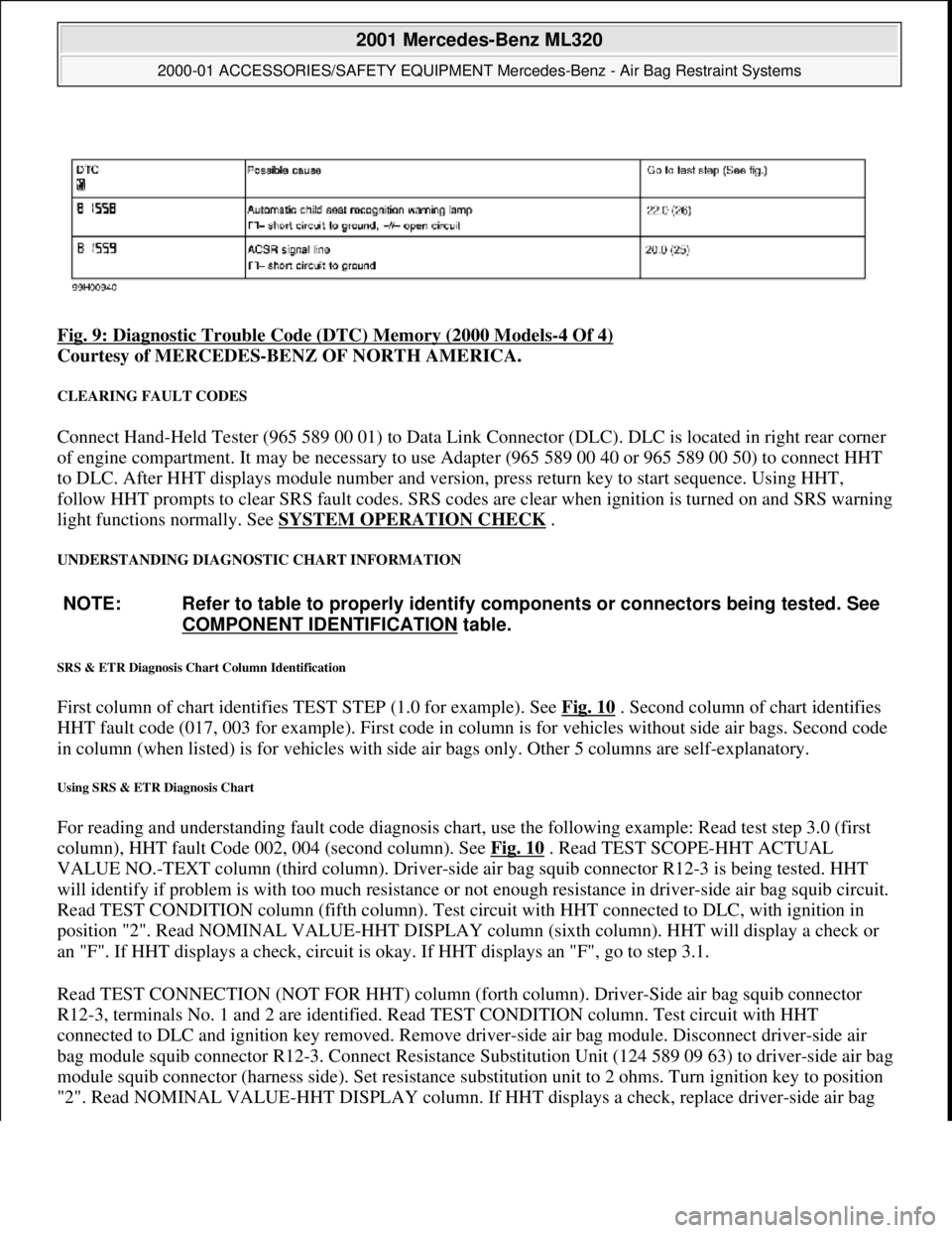
Fig. 9: Diagnostic Trouble Code (DTC) Memory (2000 Models-4 Of 4)
Courtesy of MERCEDES-BENZ OF NORTH AMERICA.
CLEARING FAULT CODES
Connect Hand-Held Tester (965 589 00 01) to Data Link Connector (DLC). DLC is located in right rear corner
of engine compartment. It may be necessary to use Adapter (965 589 00 40 or 965 589 00 50) to connect HHT
to DLC. After HHT displa ys module number and version, press return key to start sequence. Using HHT,
follow HHT prompts to clear SRS faul t codes. SRS codes are clear when ignition is turned on and SRS warning
light functions normally. See SYSTEM OPERATION CHECK
.
UNDERSTANDING DIAGNOSTIC CHART INFORMATION
SRS & ETR Diagnosis Chart Column Identification
First column of chart identifies TEST STEP (1.0 for example). See Fig. 10 . Second column of chart identifies
HHT fault code (017, 003 for example). First code in column is for ve hicles without side air bags. Second code
in column (when listed) is for ve hicles with side air bags only. Ot her 5 columns are self-explanatory.
Using SRS & ETR Diagnosis Chart
For reading and understanding fault code diagnosis chart, use the following example: Read test step 3.0 (first
column), HHT fault Code 002, 004 (second column). See Fig. 10
. Read TEST SCOPE-HHT ACTUAL
VALUE NO.-TEXT column (third column). Driver-side air bag squib connector R12-3 is being tested. HHT
will identify if problem is with too much resistance or not enough resistance in driver-side air bag squib circuit.
Read TEST CONDITION column (fifth column). Test ci rcuit with HHT connected to DLC, with ignition in
position "2". Read NOMINAL VALUE-HHT DISPLAY column (sixth column). HHT will display a check or
an "F". If HHT displays a check, circuit is okay. If HHT displays an "F", go to step 3.1.
Read TEST CONNECTION (NOT FOR HHT) column (fort h column). Driver-Side air bag squib connector
R12-3, terminals No. 1 and 2 are id entified. Read TEST CONDITION column. Test circuit with HHT
connected to DLC and igni tion key removed. Remove driver-side air bag module. Disconnect driver-side air
bag module squib connector R12-3. Conn ect Resistance Substitution Unit (124 589 09 63) to driver-side air bag
module squib connector (harness side). Set resistance substitution unit to 2 ohms. Turn ignition key to position
"2". Read NOMINAL VALUE-HHT DISPLAY column. If HHT displa
ys a check, replace driver-side air bag
NOTE: Refer to table to properly identify components or connectors being tested. See
COMPONENT IDENTIFICATION
table.
2001 Mercedes-Benz ML320
2000-01 ACCESSORIES/SAFETY EQUIPMENT Merc edes-Benz - Air Bag Restraint Systems
me
Saturday, October 02, 2010 3:44:46 PMPage 20 © 2006 Mitchell Repair Information Company, LLC.
Page 385 of 4133
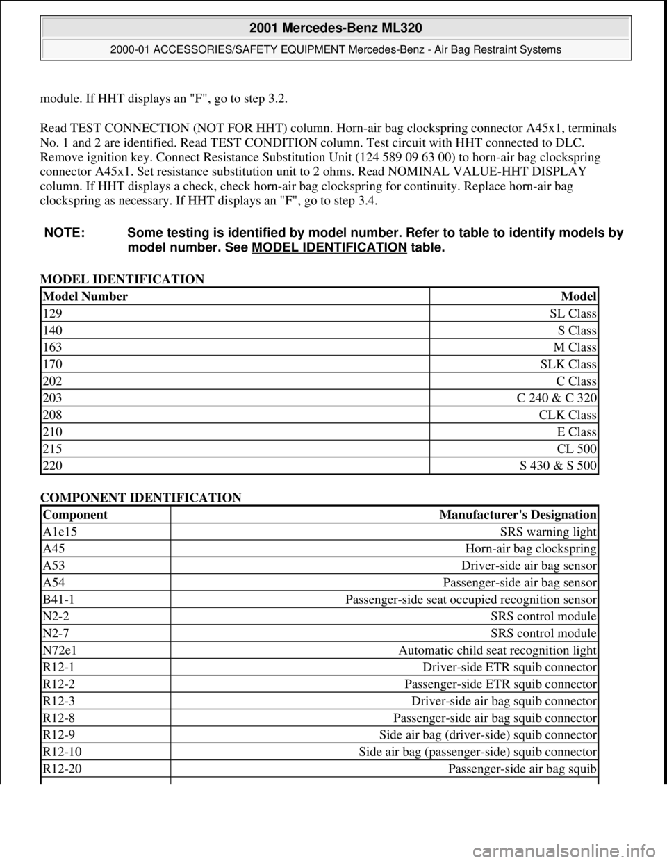
module. If HHT displays an "F", go to step 3.2.
Read TEST CONNECTION (NOT FOR HHT) column. Horn -air bag clockspring connector A45x1, terminals
No. 1 and 2 are identified. Read TEST CONDITION column. Test circuit with HHT connected to DLC.
Remove ignition key. Connect Resist ance Substitution Unit (124 589 09 63 00) to horn-air bag clockspring
connector A45x1. Set resistance s ubstitution unit to 2 ohms. Read NOMINAL VALUE-HHT DISPLAY
column. If HHT displays a check, check horn-air ba g clockspring for continuity. Replace horn-air bag
clockspring as necessary. If HHT displays an "F", go to step 3.4.
MODEL IDENTIFICATION
COMPONENT IDENTIFICATION
NOTE: Some testing is identified
by model number. Refer to table to identify models by
model number. See MO DEL IDENTIFICATION
table.
Model NumberModel
129SL Class
140S Class
163M Class
170SLK Class
202C Class
203C 240 & C 320
208CLK Class
210E Class
215CL 500
220S 430 & S 500
ComponentManufacturer's Designation
A1e15SRS warning light
A45Horn-air bag clockspring
A53Driver-side air bag sensor
A54Passenger-side air bag sensor
B41-1Passenger-side seat occupied recognition sensor
N2-2SRS control module
N2-7SRS control module
N72e1Automatic child seat recognition light
R12-1Driver-side ETR squib connector
R12-2Passenger-side ETR squib connector
R12-3Driver-side air bag squib connector
R12-8Passenger-side air bag squib connector
R12-9Side air bag (driver-side) squib connector
R12-10Side air bag (passenge r-side) squib connector
R12-20Passenger-side air bag squib
2001 Mercedes-Benz ML320
2000-01 ACCESSORIES/SAFETY EQUIPMENT Merc edes-Benz - Air Bag Restraint Systems
me
Saturday, October 02, 2010 3:44:46 PMPage 21 © 2006 Mitchell Repair Information Company, LLC.
Page 486 of 4133
19
Instruments and controls
Te ch n ica l
data
Instruments
and controls Operation Driving
Instrument
cluster display Practical hints Car care Index
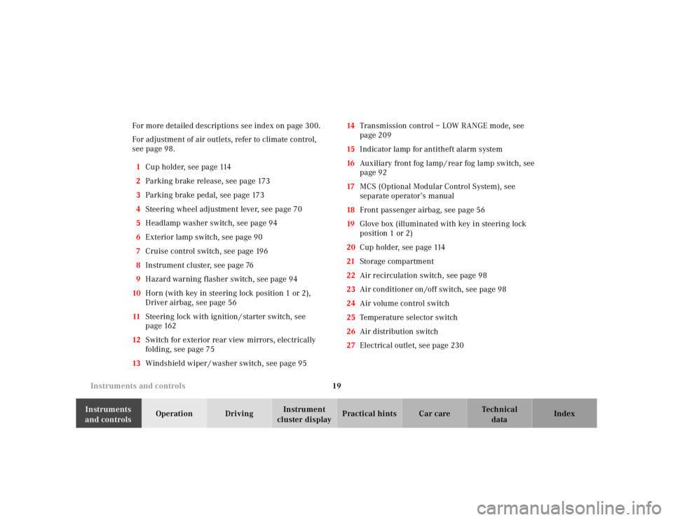
For more detailed descriptions see index on page 300.
For adjustment of air outlets, refer to climate control,
see page 98.
1 Cup holder, see page 114
2 Parking brake release, see page 173
3 Parking brake pedal, see page 173
4 Steering wheel adjustment lever, see page 70
5 Headlamp washer switch, see page 94
6 Exterior lamp switch, see page 90
7 Cruise control switch, see page 196
8 Instrument cluster, see page 76
9 Hazard warning flasher switch, see page 94
10 Horn (with key in steering lock position 1 or 2),
Driver airbag, see page 56
11 Steering lock with ignition / starter switch, see
page 162
12 Switch for exterior rear view mirrors, electrically
folding, see page 75
13 Windshield wiper / washer switch, see page 95 14
Transmission control – LOW RANGE mode, see
page 209
15 Indicator lamp for antitheft alarm system
16 Auxiliary front fog lamp / rear fog lamp switch, see
page 92
17 MCS (Optional Modular Control System), see
separate operator’s manual
18 Front passenger airbag, see page 56
19 Glove box (illuminated with key in steering lock
position 1 or 2)
20 Cup holder, see page 114
21 Storage compartment
22 Air recirculation switch, see page 98
23 Air conditioner on /off switch, see page 98
24 Air volume control switch
25 Temperature selector switch
26 Air distribution switch
27 Electrical outlet, see page 230
Page 525 of 4133
58
Restraint systems
Te ch n ica l
data
Instruments
and controls Operation
Driving Instrument
cluster display Practical hints Car care Index
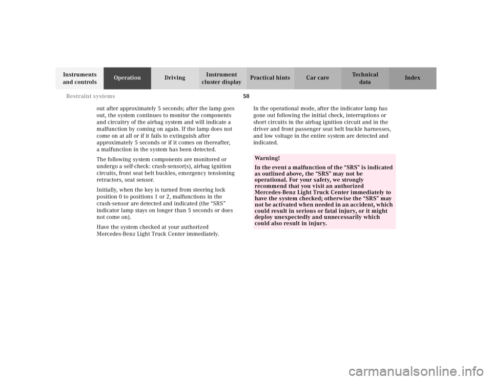
out after approximately 5 seconds; after the lamp goes
out, the system continues to monitor the components
and circuitry of the airbag system and will indicate a
malfunction by coming on again. If the lamp does not
come on at all or if it fails to extinguish after
approximately 5 seconds or if it comes on thereafter,
a malfunction in the system has been detected.
The following system components are monitored or
undergo a self-check: crash-sensor(s), airbag ignition
circuits, front seat belt buckles, emergency tensioning
retractors, seat sensor.
Initially, when the key is turned from steering lock
position 0 to positions 1 or 2, malfunctions in the
crash-sensor are detected and indicated (the “SRS”
indicator lamp stays on longer than 5 seconds or does
not come on).
Have the system checked at your authorized
Mercedes-Benz Light Truck Center immediately. In the operational mode, after the indicator lamp has
gone out following the initial check, interruptions or
short circuits in the airbag ignition circuit and in the
driver and front passenger seat belt buckle harnesses,
and low voltage in the entire system are detected and
indicated.
Wa r n i n g !
In the event a malfunction of the “SRS” is indicated
as outlined above, the “SRS” may not be
operational. For your safety, we strongly
recommend that you visit an authorized
Mercedes-Benz Light Truck Center immediately to
have the system checked; otherwise the “SRS” may
not be activated when needed in an accident, which
could result in serious or fatal injury, or it might
deploy unexpectedly and unnecessarily which
could also result in injury.
Page 699 of 4133
232
Engine compartment
Te ch n ica l
data
Instruments
and controls Operation Driving
Instrument
cluster display Practical hints
Car care Index
Wa r n i n g !
To help prevent personal injury, stay clear of
moving parts when the hood is open and the engine
is running. Be sure the hood is properly closed
before driving. When closing hood, use extreme
caution not to catch hands or fingers.The radiator fan may continue to run for
approximately 30 seconds or even restart after the
engine has been turned off. Stay clear from fan
blades.
The engine is equipped with a transistorized
ignition system. Because of the high voltage it is
dangerous to touch any components (ignition coils,
spark plug sockets, diagnostic socket) of the
ignition system
• with the engine running,
• while starting the engine,
• if ignition is “on” and the engine is turned manually.If you see flames, steam or smoke coming from the
engine compartment, or if the coolant temperature
gauge indicates that the engine is overheated, do
not open the hood. Move away from vehicle and do
not open the hood until the engine has cooled. If
necessary, call a fire department.