1997 MERCEDES-BENZ ML430 ignition
[x] Cancel search: ignitionPage 14 of 4133
check to ensure system is functioning properly. See SYSTEM OPERATION CHECK .
Removal & Installation (SLK 230)
1. Before proceeding, see SERVICE PRECAUTIONS . Disable air bag system. See DISABLING &
ACTIVATING AIR BAG SYSTEM . Remove ignition key. Remove top section of instrument panel.
Fold vapor barrier toward front to reveal 2 screws. Disconnect passenger-side air bag module connector.
Remove 4 screws and passenger-side air bag module.
2. To install air bag module, reverse removal procedure. Activate air bag system. Perform system operation
check to ensure system is functioning properly. See SYSTEM OPERATION CHECK
.
SYSTEM OPERATION CHECK
SRS warning light indicates air bag and Emergency Tensioning Retractor (ETR) system readiness. Turn
ignition on. SRS warning light will light, and then go out after approximately 4 seconds indicating system is
functioning properly. If SRS warning light does not light, lights up while driving or lights all the time, there is a
system fault. Repair malfunctioning system. See DIAGNOSIS & TESTING
.
SERVICE PRECAUTIONS
Observe following precautions when working with air bag systems:
When working around steering column components and before any repairs are performed, disable air bag
system. See DISABLING & ACTIVATING AIR BAG SYSTEM
.
Before straightening any damage to body, or before performing electrical arc-welding, disable air bag
system. See DISABLING & ACTIVATING AIR BAG SYSTEM
.
Always wear safety glasses and gloves when handling a deployed air bag module. Air bag module may
contain sodium hydroxide deposits which are irritating to the skin.
DO NOT repair any portion of SRS wiring harness.
Always handle air bag module with trim cover away from your body. Always place air bag module on
workbench with trim cover up, away from loose objects.
DO NOT expose any SRS component to temperatures in excess of 212°F (100°C).
DO NOT expose any SRS component to cleaning agents such as solvents, gasoline, lye, etc.
DO NOT connect Hand-Held Tester (6511 0001 99) to Data Link Connector (DLC) with ignition on.
Damage to HHT may result.
DO NOT connect HHT (6511 0001 99) to vehicle if a battery charger is connected to vehicle battery.
Damage to HHT may result.
DISABLING & ACTIVATING AIR BAG SYSTEM DISABLING SYSTEM
Before proceeding, follow air bag service precautions. See SERVICE PRECAUTIONS
. Turn ignition off.
Disconnect and shield negative battery cable. Remove passenger foot mat. Remove passenger footrest.
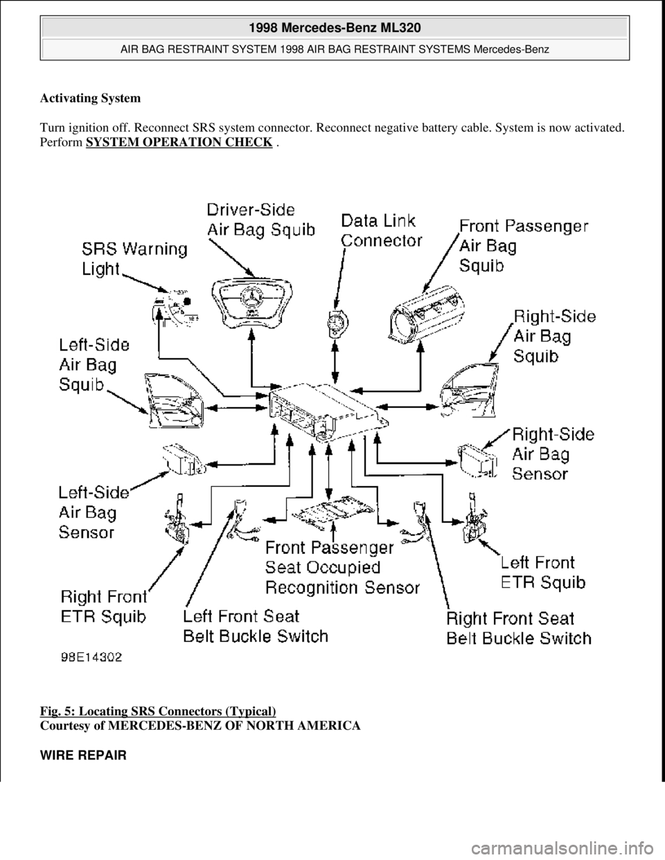
Disconnect SRS system connector (X29/9) located at passenger footwell area. See Fig. 5
. System is now
disabled.
1998 Mercedes-Benz ML320
AIR BAG RESTRAINT SYSTEM 1998 AIR BAG RESTRAINT SYSTEMS Mercedes-Benz
me
Saturday, October 02, 2010 3:33:14 PMPage 14 © 2006 Mitchell Repair Information Company, LLC.
Page 15 of 4133
Activating System
Turn ignition off. Reconnect SRS syst em connector. Reconnect negative batt ery cable. System is now activated.
Perform SYSTEM OPERATION CHECK
.
Fig. 5: Locating SRS Connectors (Typical)
Courtesy of MERCEDES-BENZ OF NORTH AMERICA
WIRE REPAIR
1998 Mercedes-Benz ML320
AIR BAG RESTRAINT SYSTEM 1998 AIR BAG RESTRAINT SYSTEMS Mercedes-Benz
me
Saturday, October 02, 2010 3:33:14 PMPage 15 © 2006 Mitchell Repair Information Company, LLC.
Page 16 of 4133
If any part of SRS wiring harness is damaged, DO NOT repair wiring harness, replace complete wiring harness.
TORQUE SPECIFICATIONS
TORQUE SPECIFICATIONS
(1)
DIAGNOSIS & TESTING
Before proceeding, see SERVICE PRECAUTIONS
. The control module is capable of diagnosing airbag
system components and ETR components. If a fault is detected by the control module or system is
malfunctioning, SRS warning light will do one or more of the following:
SRS warning light goes out after 2 minutes. System fault is noted, however occupant protection is not
affected. See RETRIEVING FAULT CODES
.
SRS warning light illuminates continuously. System is faulty which may result in a non deployment or
false deployment. See RETRIEVING FAULT CODES
.
SRS warning light blinks continuously. Control module has been replaced without setting control module
parameters.
RETRIEVING FAULT CODES
1. Check vehicle fuses. Replace any blown fuses as necessary. Ensure vehicle battery voltage is 11 volts or
more. Ensure SRS warning light functions. Turn ignition off. Connect Hand-Held Tester (HHT) (965 589
00 01) to Data Link Connector (DLC).
2. DLC is located in right rear corner of engine compartment. It may be necessary to use Adapter (965 589
00 40 or 965 589 00 50) to connect HHT to DLC. After HHT displays module number and version, press
return key to start diagnosis. Using HHT, follow HHT prompts to retrieve SRS fault codes.
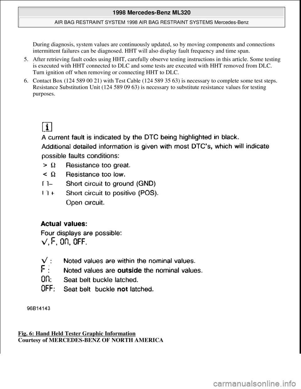
3. HHT will display a 3 digit fault code, and may display additional graphic information. This additional
graphic information will help in diagnosis of fault code. See Fig. 6
. During diagnosis HHT will display 4
different graphic displays informing technician if a test passes or fails, or if seat belt buckle is latched or
not latched. See Fig. 6
.
4. These
graphic displays are displayed as applicable by HHT during testing. See FAULT CODES table.
ApplicationFt. Lbs. (N.m)
Steering Wheel Hub Bolt52-66 (70-90)
INCH Lbs. (N.m)
Driver Air Bag Module Bolts (Torx)44-62 (5-7)
(1)Torque specifications are not available for clockspring assembly, control module or passenger-side
air bag module.
NOTE: After component replacement, perform a system operation check to ensure
proper system operation. See SYSTEM OPERATION CHECK
.
NOTE: Fault codes may only be retrieved using Hand-Held Tester (965 589 00 01) and
Adapter (965 589 00 40 or 965 589 00 50).
1998 Mercedes-Benz ML320
AIR BAG RESTRAINT SYSTEM 1998 AIR BAG RESTRAINT SYSTEMS Mercedes-Benz
me
Saturday, October 02, 2010 3:33:14 PMPage 16 © 2006 Mitchell Repair Information Company, LLC.
Page 17 of 4133
During diagnosis, system values are continuously updated, so by moving components and connections
intermittent failures can be diagnosed. HHT will also display fault frequency and time span.
5. After retrieving fault codes using HHT, carefully observe testing instructions in this article. Some testing
is executed with HHT connected to DLC and some tests are executed with HHT removed from DLC.
Turn ignition off when removing or connecting HHT to DLC.
6. Contact Box (124 589 00 21) with Test Cable (124 589 35 63) is necessary to complete some test steps.
Resistance Substitution Unit (124 589 09 63) is necessary to substitute resistance values for testing
purposes.
Fig. 6: Hand Held Tester Graphic Information
Courtesy of MERCEDES-BENZ OF NORTH AMERICA
1998 Mercedes-Benz ML320
AIR BAG RESTRAINT SYSTEM 1998 AIR BAG RESTRAINT SYSTEMS Mercedes-Benz
me
Saturday, October 02, 2010 3:33:14 PMPage 17 © 2006 Mitchell Repair Information Company, LLC.
Page 19 of 4133
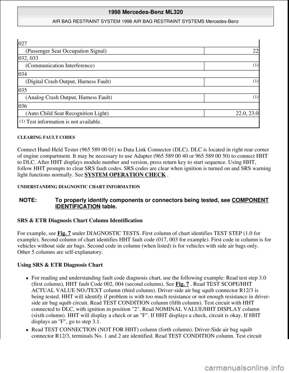
CLEARING FAULT CODES
Connect Hand-Held Tester (965 589 00 01) to Data Link Connector (DLC). DLC is located in right rear corner
of engine compartment. It may be necessary to use Adapter (965 589 00 40 or 965 589 00 50) to connect HHT
to DLC. After HHT displays module number and version, press return key to start sequence. Using HHT,
follow HHT prompts to clear SRS fault codes. SRS codes are clear when ignition is turned on and SRS warning
light functions normally. See SYSTEM OPERATION CHECK
.
UNDERSTANDING DIAGNOSTIC CHART INFORMATION
SRS & ETR Diagnosis Chart Column Identification
For example, see Fig. 7
under DIAGNOSTIC TESTS. First column of chart identifies TEST STEP (1.0 for
example). Second column of chart identifies HHT fault code (017, 003 for example). First code in column is for
vehicles without side air bags. Second code in column (when listed) is for vehicles with side air bags only.
Other 5 columns are self-explanatory.
Using SRS & ETR Diagnosis Chart
For reading and understanding fault code diagnosis chart, use the following example: Read test step 3.0
(first column), HHT fault Code 002, 004 (second column). See Fig. 7
. Read TEST SCOPE/HHT
ACTUAL VALUE NO./TEXT column (third column). Driver-side air bag squib connector R12/3 is
being tested. HHT will identify if problem is with too much resistance or not enough resistance in driver-
side air bag squib circuit. Read TEST CONDITION column (fifth column). Test circuit with HHT
connected to DLC, with ignition in position "2". Read NOMINAL VALUE/HHT DISPLAY column
(sixth column). HHT will display a check or an "F". If HHT displays a check, circuit is okay. If HHT
displays an "F", go to step 3.1.
Read TEST CONNECTION (NOT FOR HHT) column (forth column). Driver-Side air bag squib
connector R12/3, terminals No. 1 and 2 are identified. Read TEST CONDITION column. Test circuit
027
(Passenger Seat Occupation Signal)22
032, 033
(Communication Interference)(1)
034
(Digital Crash Output, Harness Fault)(1)
035
(Analog Crash Output, Harness Fault)(1)
036
(Auto Child Seat Recognition Light)22.0, 23.0
(1)Test information is not available.
NOTE: To properly identify components or connectors being tested, see COMPONENT
IDENTIFICATION table.
1998 Mercedes-Benz ML320
AIR BAG RESTRAINT SYSTEM 1998 AIR BAG RESTRAINT SYSTEMS Mercedes-Benz
me
Saturday, October 02, 2010 3:33:14 PMPage 19 © 2006 Mitchell Repair Information Company, LLC.
Page 20 of 4133
with HHT connected to DLC and ignition key removed. Remove driver-side air bag module. Disconnect
driver-side air bag module squib connector R12/3. Connect Resistance Substitution Unit (124 589 09 63)
to driver-side air bag module squib connector (harness side). Set resistance substitution unit to 2 ohms.
Turn ignition key to position "2". Read NOMINAL VALUE/HHT DISPLAY column. If HHT displays a
check, replace driver-side air bag module. If HHT displays an "F", go to step 3.2.
Read TEST CONNECTION (NOT FOR HHT) column. Horn/air bag clockspring connector A45x1,
terminals No. 1 and 2 are identified. Read TEST CONDITION column. Test circuit with HHT connected
to DLC. Remove ignition key. Connect Resistance Substitution Unit (124 589 09 63 00) to horn/air bag
clockspring connector A45x1. Set resistance substitution unit to 2 ohms. Read NOMINAL VALUE/HHT
DISPLAY column. If HHT displays a check, check horn/air bag clockspring for continuity. Replace
horn/air bag clockspring as necessary. If HHT displays an "F", go to step 3.4.
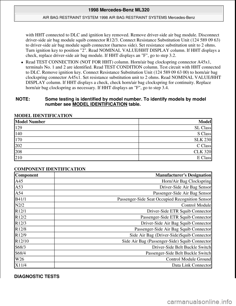
MODEL IDENTIFICATION
COMPONENT IDENTIFICATION
DIAGNOSTIC TESTS NOTE: Some testing is identified by model number. To identify models by model
number see MODEL IDENTIFICATION
table.
Model NumberModel
129SL Class
140S Class
170SLK 230
202C Class
208CLK 320
210E Class
ComponentManufacturer's Designation
A45Horn/Air Bag Clockspring
A53Driver-Side Air Bag Sensor
A54Passenger-Side Air Bag Sensor
B41/1Passenger-Side Seat Occupied Recognition Sensor
N2/2Control Module
R12/1Driver-Side ETR Squib Connector
R12/2Passenger-Side ETR Squib Connector
R12/3Driver-Side Air Bag Squib Connector
R12/8Passenger-Side Air Bag Squib Connector
R12/9Side Air Bag (Driver-Side)Squib Connector
R12/10Side Air Bag (Passenger-Side) Squib Connector
S68/3Driver-Side Belt Buckle Switch
S68/4Passenger-Side Belt Buckle Switch
W26Control Module Ground
X11/4Data Link Connector
1998 Mercedes-Benz ML320
AIR BAG RESTRAINT SYSTEM 1998 AIR BAG RESTRAINT SYSTEMS Mercedes-Benz
me
Saturday, October 02, 2010 3:33:14 PMPage 20 © 2006 Mitchell Repair Information Company, LLC.
Page 69 of 4133

19 Instruments and controls
Te ch n ica l
data Instruments
and controlsOperation DrivingInstrument
cluster displayPractical hints Car care Index For more detailed descriptions see index on page 300.
For adjustment of air outlets, refer to climate control,
see page 98.
1Cup holder, see page 114
2Parking brake release, see page 173
3Parking brake pedal, see page 173
4Steering wheel adjustment lever, see page 70
5Headlamp washer switch, see page 94
6Exterior lamp switch, see page 90
7Cruise control switch, see page 196
8Instrument cluster, see page 76
9Hazard warning flasher switch, see page 94
10Horn (with key in steering lock position 1 or 2),
Driver airbag, see page 56
11Steering lock with ignition / starter switch, see
page 162
12Switch for exterior rear view mirrors, electrically
folding, see page 75
13Windshield wiper / washer switch, see page 9514Transmission control – LOW RANGE mode, see
page 209
15Indicator lamp for antitheft alarm system
16Auxiliary front fog lamp / rear fog lamp switch, see
page 92
17MCS (Optional Modular Control System), see
separate operator’s manual
18Front passenger airbag, see page 56
19Glove box (illuminated with key in steering lock
position 1 or 2)
20Cup holder, see page 114
21Storage compartment
22Air recirculation switch, see page 98
23Air conditioner on /off switch, see page 98
24Air volume control switch
25Temperature selector switch
26Air distribution switch
27Electrical outlet, see page 230
Page 108 of 4133
58 Restraint systems
Te ch n ica l
data Instruments
and controlsOperationDrivingInstrument
cluster displayPractical hints Car care Index
out after approximately 5 seconds; after the lamp goes
out, the system continues to monitor the components
and circuitry of the airbag system and will indicate a
malfunction by coming on again. If the lamp does not
come on at all or if it fails to extinguish after
approximately 5 seconds or if it comes on thereafter,
a malfunction in the system has been detected.
The following system components are monitored or
undergo a self-check: crash-sensor(s), airbag ignition
circuits, front seat belt buckles, emergency tensioning
retractors, seat sensor.
Initially, when the key is turned from steering lock
position 0 to positions 1 or 2, malfunctions in the
crash-sensor are detected and indicated (the “SRS”
indicator lamp stays on longer than 5 seconds or does
not come on).
Have the system checked at your authorized
Mercedes-Benz Light Truck Center immediately.In the operational mode, after the indicator lamp has
gone out following the initial check, interruptions or
short circuits in the airbag ignition circuit and in the
driver and front passenger seat belt buckle harnesses,
and low voltage in the entire system are detected and
indicated.
Wa r n i n g !
In the event a malfunction of the “SRS” is indicated
as outlined above, the “SRS” may not be
operational. For your safety, we strongly
recommend that you visit an authorized
Mercedes-Benz Light Truck Center immediately to
have the system checked; otherwise the “SRS” may
not be activated when needed in an accident, which
could result in serious or fatal injury, or it might
deploy unexpectedly and unnecessarily which
could also result in injury.