1997 MERCEDES-BENZ ML430 ignition
[x] Cancel search: ignitionPage 2048 of 4133

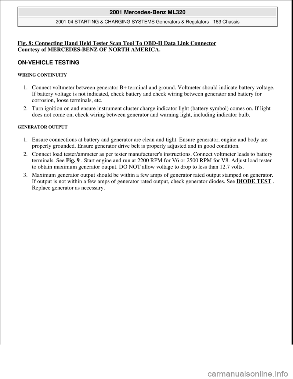
Fig. 8: Connecting Hand Held Tester Scan Tool To OBD-II Data Link Connector
Courtesy of MERCEDES-BENZ OF NORTH AMERICA.
ON-VEHICLE TESTING
WIRING CONTINUITY
1. Connect voltmeter between generator B+ terminal and ground. Voltmeter should indicate battery voltage.
If battery voltage is not indicated, check battery and check wiring between generator and battery for
corrosion, loose terminals, etc.
2. Turn ignition on and ensure instrument cluster charge indicator light (battery symbol) comes on. If light
does not come on, check wiring between generator and warning light, including indicator bulb.
GENERATOR OUTPUT
1. Ensure connections at battery and generator are clean and tight. Ensure generator, engine and body are
properly grounded. Ensure generator drive belt is properly adjusted and in good condition.
2. Connect load tester/ammeter as per tester manufacturer's instructions. Connect voltmeter leads to battery
terminals. See Fig. 9
. Start engine and run at 2200 RPM for V6 or 2500 RPM for V8. Adjust load tester
to obtain maximum generator output. DO NOT allow voltage to drop to less than 12.7 volts.
3. Maximum generator output should be within a few amps of generator rated output stamped on generator.
If output is not within a few amps of generator rated output, check generator diodes. See DIODE TEST
.
Replace
generator as necessary.
2001 Mercedes-Benz ML320
2001-04 STARTING & CHARGING SYSTEMS Generators & Regulators - 163 Chassis
me
Saturday, October 02, 2010 3:20:32 PMPage 14 © 2006 Mitchell Repair Information Company, LLC.
Page 2065 of 4133

SI54.50-P-0001A
Service Information: Compass in trip computer
22.10.00
MODELS
163.113 /154 /172 as of 1.9.00,
163.128 /157 /174 /175 with CODE (245) Trip computer
The compass is calibrated in the factory in order to compensate
for deviations caused by magnetic field intensity of the vehicle and
magnetic interference when operating the heated rear window.
Once the compass is calibrated, it never needs to be recalibrated
under normal operating conditions. If a strong deviation in magnetic
field intensity is detected, the compass automatically recalibrates
itself.
A calibration must be carried out if the compass is replaced.
Additionally, the user can fine tune the compass in order to adapt
it to the vehicle's surrounding area. By setting the respective
compass zone, the compass compensates for deviations in the
earth's magnetic field.
The calibration should take place at least 10 m from any source of
interference such as power lines, buildings and parked vehicles.
Zone setting
1
Press the MODE button on the trip computer
until the compass direction is displayed
2
Press the RESET button once
The current compass zone is displayed
3
Press the RESET button until the desired
compass zone is displayed
The maps for determining the correct
compass zone can be found in the owner's
manual. If the RESET button is not pressed
within 5 seconds, the point of the compass is
displayed again.
Compass calibration
4
Bring the compass to the compass zone
display mode
5
Press the MODE button once
Display shows
CAL-
on.
6
Press the RESET button for at least 2 seconds
The hyphen (
-
) in the display disappears.
The calibration mode is active and remains
active until the calibration process has
concluded. If the ignition is switched off and
on, calibration mode remains active, even if
CAL
no longer is displayed.
7
Drive two complete circles at a speed of
between 5 - 10 km/h
Heated rear window switched off.
8
Switch heated rear window on
9
Drive three full circles at a speed from 5 - 10
km/h.
Calibration process concluded.
Although the display can change from
CAL
to
the point of the compass before the
calibration drive has been concluded, the
calibration process is still active and must be
carried out exactly as described.
Copyright DaimlerChrysler AG 18.05.2006 CD-Ausgabe G/10/04 . This WIS print-out will not be recorde
d by Modification services.
Page 1
Page 2067 of 4133

GF72.29-P-2002GH
Convenience control, function
7.4.97
MODEL
163
The convenience control allows the driver to operate the electrical
seat adjustment, the power windows, the electric vent windows, the
electric outside rearview mirror as well as the electric sliding/pop-up
roof or the electric lamella sliding roof
when the ignition is switched
off.
To achieve this, the all-activity module (AAM) (N10) switches to the
corresponding loads via the convenience relay (F1k14)
circuit 30 .
As of 12.99 the vehicle is equipped with its own convenience relay for
seat adjustment (relay 1, F2k1). In addition the status of the
convenience control via CAN is transmitted to the extended activity
module (EAM, N10/1).
Conditions for control actuation
On all-activity module (AAM) (N10) configured for
I
up
to
11.99:
The convenience actuation becomes active as soon as
D
Circuit 15 ON is recognized
When circuit 15 is switched off, the convenience actuation is
deactivated after a door is opened
Otherwise
The convenience actuation is active in the following cases:
D
Circuit 15c ON
D
A front door is open
D
The remote control key is removed, however, the doors are not
yet opened
In both cases the convenience actuation remains active for 5 min.
Switch-on condition for circuit 15c
When the remote control key is inserted into the ignition lock, circuit
15c is switched on when the key is turned out of the zero position.
Circuit 15c switches off only after the remote control key is removed
from the ignition lock
Electric seat adjustment without memory,
function
GF91.29-P-0003GH
Electric seat adjustment with memory, function
as of 12.99
GF91.29-P-0002GH
Convenience control, function
for electrical seat adjustment as of 12.99
GF91.29-P-2013GK
Power windows, function
GF72.29-P-0003GH
Power tilting/sliding roof (SR), function
GF77.20-P-0001GH
Electrically adjustable outside rearview
mirrors, function
GF88.79-P-0005GH
Electric vent windows, function
GF67.39-P-1000GH
Extended activity module,
location/purpose/design
as of 12.99
GF54.21-P-4107GK
Copyright DaimlerChrysler AG 04.08.2006 CD-Ausgabe G/10/04 . This WIS print-out will not be recorde
d by Modification services.
Page 1
Page 2085 of 4133

AR01.30-P-5800MV
Remove/install cylinder head
22.7.98
ENGINE
112.942 in MODEL 163.154
ENGINE
112.970 in MODEL 163.157
ENGINE
113.942 in MODEL 163.172
ENGINE
113.981 in MODEL 163.174
ENGINE
113.965 in MODEL 163.175
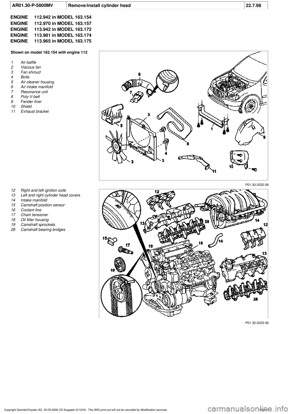
P01.30-2032-06
Shown on model 163.154 with engine 112
1
Air baffle
2
Viscous fan
3
Fan shroud
4
Bolts
5
Air cleaner housing
6
Air intake manifold
7
Resonance unit
8
Poly-V-belt
9
Fender liner
10
Shield
11
Exhaust bracket
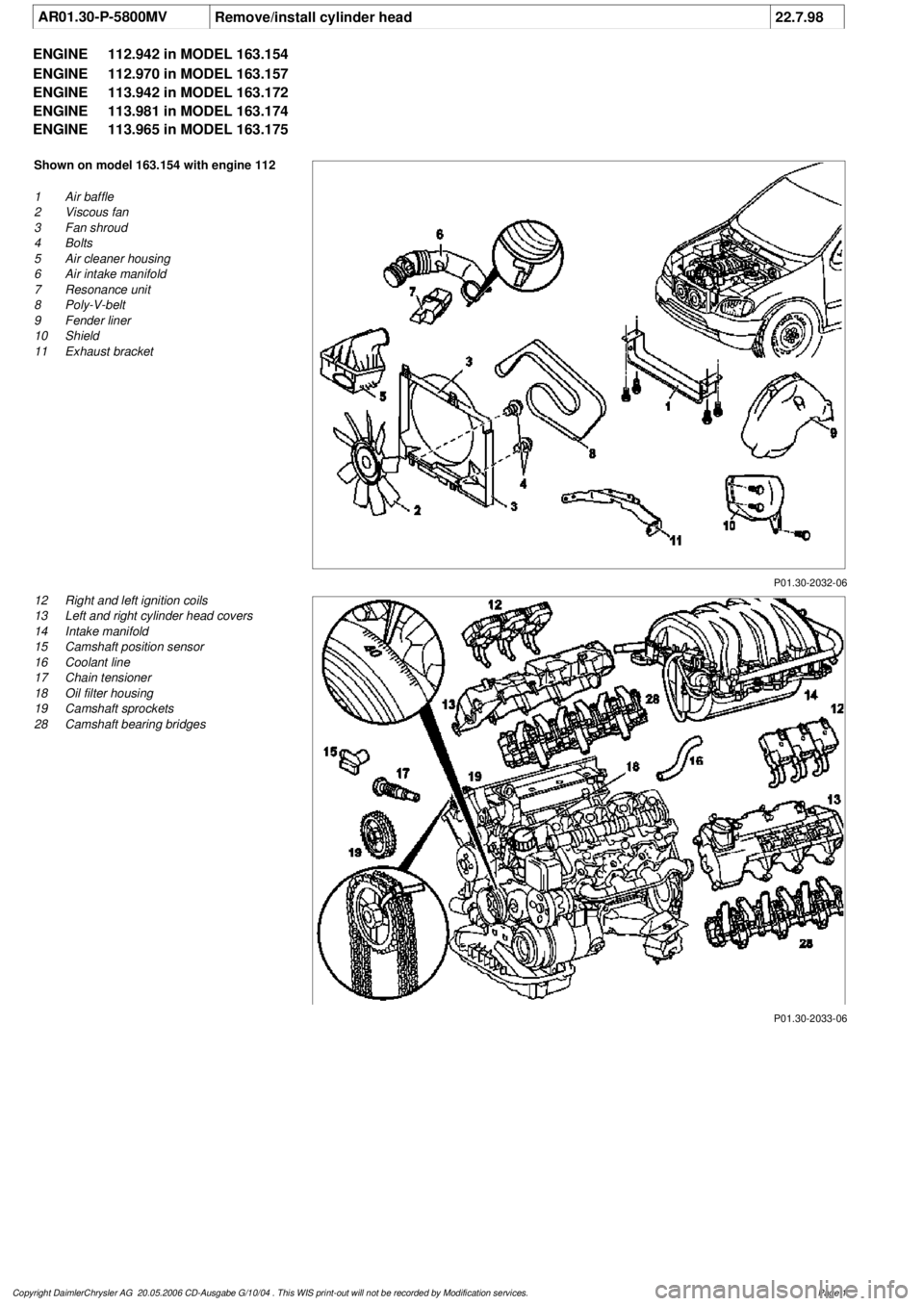
P01.30-2033-06
12
Right and left ignition coils
13
Left and right cylinder head covers
14
Intake manifold
15
Camshaft position sensor
16
Coolant line
17
Chain tensioner
18
Oil filter housing
19
Camshaft sprockets
28
Camshaft bearing bridges
Copyright DaimlerChrysler AG 20.05.2006 CD-Ausgabe G/10/04 . This WIS print-out will not be recorde
d by Modification services.
Page 1
Page 2087 of 4133

8
Attach guard plate for radiator/condenser
y
Guard plate for radiator/condenser
Engine 606 in model 124,
Engine 606.961 in model 140,
Engine 112, 113, 604, 605, 611.960 in model
202,
Engine 602.983, 612.966 in model 461,
Engine 628.962, 612.965, 606.964, 112.945,
113.962/ 982 in model 463,
Engine 111, 112, 611.962, 612.962 in model
203,
Engine 112, 113, 611.961, 612.961, 613.961
in model 210,
Engine 112 in model 170,
Engine 112 in model 220,
Engine 113 in model 211, 215, 220,
Engine 112 in model 208,
Engine 112, 113, 612.963, 628.963 in model
163,
Engine 112.923 /943, 113.961 in model 129,
Engine 137, 275 in model 215, 220,
Engine 613.960, 628.960 in model 220,
Engine 113.992 in model 230.474,
Engine 271 in model 209, 203,
Engine 285.950 in model 240.078 /178,
Engine 612.967 in model 209.316,
Engine 648 in model 220
Engine 112.951 in model 639.601/603/ 605/
701 /703 /705 /801 /803 /805
Engine 646.983 /984 in model 639.601/
603 /605 /701 /703 /705 /801 /803 /805
Engine 646.982 in model 639.601/ 603/ 605/
701 /703 /705
WF58.50-P-0110-01A
9
Remove air cleaner housing (5)
10
Remove air intake pipe (6) with resonance
tube (7)
Separate connector of hot film mass air
flow sensor (HFM) for this step and unbolt air
intake pipe at cylinder head cover
The air intake pipe is attached at the rear
at the intake manifold with a plastic plate.
Do not damage the plastic strap.
Engine 112.942/ 970
AR07.07-P-1454A
Engine 113.942/ 965/ 981
AR07.07-P-1454MV
Danger!
Risk of explosion
caused by fuel igniting,
risk of poisoning
caused by inhaling and
swallowing fuel as well as
risk of injury
to
eyes and skin caused by contact with fuel.
No fire, sparks, open flames or smoking.
Pour fuels only into suitable and appropriately
marked containers.
Wear protective clothing when handling fuel.
AS47.00-Z-0001-01A
11
Disconnect fuel line at fuel rail
Release fuel pressure at service valve!
Collect fuel!
Engine 112:
#
*BA07.52-P-1001-01A
Engine 113:
#
*BA07.52-P-1001-01A
Pressure hose
*119589046300
12
Remove right and left ignition coils (12)
AR15.12-P-2003A
13
Remove right and left cylinder head covers (13)
AR01.20-P-5014B
14
Remove the intake manifold (14)
Installation:
On vehicles with engine
damage, the intake manifold must be
examined for swarfs before assembling and
any swarfs present must be removed, in order
to avoid consequential damage.
AR09.20-P-1310A
The intake manifold system must not be
disassembled.
Remove intake manifold with fuel distributor
15.1
Remove camshaft position sensor (15)
Only necessary if the right cylinder head is
removed.
AR15.10-P-2000A
Copyright DaimlerChrysler AG 20.05.2006 CD-Ausgabe G/10/04 . This WIS print-out will not be recorde
d by Modification services.
Page 3
Page 2088 of 4133

16
Remove poly V-belt (8)
Installation:
Lock tensioning device with
a drift or pin (diameter 5 mm).
Model 163.154 /157 /172.
AR13.22-P-1202B
Model 163.174 /175.
AR13.22-P-1202BA
17
Detach the coolant line (16) at the cylinder
head on the left
6 mm socket hexagon
*WH58.30-Z-1001-06A
7 mm socket hexagon
*WH58.30-Z-1002-06A
18.1
Remove fender liner (9)
Only with engine 113.113.942 /965 / 981.
AR88.10-P-1300GH
19.1
Remove shield (10)
Only with engine 113.942 /965 /981.
20.1
Remove exhaust bracket (11)
Only with engine 113.942 /965 /981.
Support exhaust system.
21
Detach exhaust system at exhaust manifold
Installation:
On vehicles with engine
damage, the exhaust system must be
examined for swarfs before assembling and
any swarfs present must be removed, in order
to avoid consequential damage.
*BA14.10-P-1002-01B
22
Position crankshaft to 40° after ignition TDC
on cylinder 1
The engine must not be turned back;
otherwise the timing chain can get jammed.
AR05.10-P-6858V
Rotate engine at the crankshaft in running
direction until scribe mark 40° on pulley/
vibration damper corresponds with scribe
mark on timing case.
The grooves on the camshafts must be
pointing toward the inner V.
23
Lock camshafts with locating plates
Locating plate
*112589003200
Locating plate
*112589013200
24
Remove chain tensioner (17)
Model 163.154 /157 with engine 112.942/
970, model 163.172 with engine 113.942.
AR05.10-P-7800C
Model 163.174 /175 with engine 113.981/ 965.
AR05.10-P-7800CA
25.1
Remove oil filter housing (18) together with oil-
water heat exchanger
Engine 113.942.
AR18.20-P-3471B
Engine 112.942/970.
AR18.20-P-3471BA
26
Unscrew camshaft sprockets (19)
If camshaft sprockets are removed,
engine must no longer be cranked, otherwise
timing chain might jam.
Engine 113.942 /965 /981:
#
Tie timing chain tight on both camshaft
sprockets with tie straps.
Engine 112.942 /970:
#
Right-hand camshaft sprocket:
Tie timing chain tight on camshaft sprocket
with tie strap.
Left-hand camshaft sprocket:
Mark camshaft sprocket to timing chain and
remove camshaft sprocket.
It is not possible for the timing chain to
jump across at the crankshaft and balancing
shaft.
After installation:
#
Inspect basic position of camshafts.
AR05.10-P-6858V
If necessary after checking:
#
Set the basic position of camshafts
AR05.20-P-6020AU
Open-end wrench
*112589000100
Insertion tool
*112589010300
Torque wrench
*001589722100
*BA05.20-P-1001-01B
27
Remove camshaft bearing bridges (28)
Pay attention to slackening and tightening
pattern!
AR05.20-P-7103AU
28
Unscrew bolts, cylinder head
!
timing case
cover (20)
*BA01.40-P-1002-01C
Copyright DaimlerChrysler AG 20.05.2006 CD-Ausgabe G/10/04 . This WIS print-out will not be recorde
d by Modification services.
Page 4
Page 2093 of 4133

AR01.30-P-5800MV
Remove/install cylinder head
22.7.98
ENGINE
112.942 in MODEL 163.154
ENGINE
112.970 in MODEL 163.157
ENGINE
113.942 in MODEL 163.172
ENGINE
113.981 in MODEL 163.174
ENGINE
113.965 in MODEL 163.175
P01.30-2032-06
Shown on model 163.154 with engine 112
1
Air baffle
2
Viscous fan
3
Fan shroud
4
Bolts
5
Air cleaner housing
6
Air intake manifold
7
Resonance unit
8
Poly-V-belt
9
Fender liner
10
Shield
11
Exhaust bracket
P01.30-2033-06
12
Right and left ignition coils
13
Left and right cylinder head covers
14
Intake manifold
15
Camshaft position sensor
16
Coolant line
17
Chain tensioner
18
Oil filter housing
19
Camshaft sprockets
28
Camshaft bearing bridges
Copyright DaimlerChrysler AG 20.05.2006 CD-Ausgabe G/10/04 . This WIS print-out will not be recorde
d by Modification services.
Page 1
Page 2095 of 4133

8
Attach guard plate for radiator/condenser
y
Guard plate for radiator/condenser
Engine 606 in model 124,
Engine 606.961 in model 140,
Engine 112, 113, 604, 605, 611.960 in model
202,
Engine 602.983, 612.966 in model 461,
Engine 628.962, 612.965, 606.964, 112.945,
113.962/ 982 in model 463,
Engine 111, 112, 611.962, 612.962 in model
203,
Engine 112, 113, 611.961, 612.961, 613.961
in model 210,
Engine 112 in model 170,
Engine 112 in model 220,
Engine 113 in model 211, 215, 220,
Engine 112 in model 208,
Engine 112, 113, 612.963, 628.963 in model
163,
Engine 112.923 /943, 113.961 in model 129,
Engine 137, 275 in model 215, 220,
Engine 613.960, 628.960 in model 220,
Engine 113.992 in model 230.474,
Engine 271 in model 209, 203,
Engine 285.950 in model 240.078 /178,
Engine 612.967 in model 209.316,
Engine 648 in model 220
Engine 112.951 in model 639.601/603/ 605/
701 /703 /705 /801 /803 /805
Engine 646.983 /984 in model 639.601/
603 /605 /701 /703 /705 /801 /803 /805
Engine 646.982 in model 639.601/ 603/ 605/
701 /703 /705
WF58.50-P-0110-01A
9
Remove air cleaner housing (5)
10
Remove air intake pipe (6) with resonance
tube (7)
Separate connector of hot film mass air
flow sensor (HFM) for this step and unbolt air
intake pipe at cylinder head cover
The air intake pipe is attached at the rear
at the intake manifold with a plastic plate.
Do not damage the plastic strap.
Engine 112.942/ 970
AR07.07-P-1454A
Engine 113.942/ 965/ 981
AR07.07-P-1454MV
Danger!
Risk of explosion
caused by fuel igniting,
risk of poisoning
caused by inhaling and
swallowing fuel as well as
risk of injury
to
eyes and skin caused by contact with fuel.
No fire, sparks, open flames or smoking.
Pour fuels only into suitable and appropriately
marked containers.
Wear protective clothing when handling fuel.
AS47.00-Z-0001-01A
11
Disconnect fuel line at fuel rail
Release fuel pressure at service valve!
Collect fuel!
Engine 112:
#
*BA07.52-P-1001-01A
Engine 113:
#
*BA07.52-P-1001-01A
Pressure hose
*119589046300
12
Remove right and left ignition coils (12)
AR15.12-P-2003A
13
Remove right and left cylinder head covers (13)
AR01.20-P-5014B
14
Remove the intake manifold (14)
Installation:
On vehicles with engine
damage, the intake manifold must be
examined for swarfs before assembling and
any swarfs present must be removed, in order
to avoid consequential damage.
AR09.20-P-1310A
The intake manifold system must not be
disassembled.
Remove intake manifold with fuel distributor
15.1
Remove camshaft position sensor (15)
Only necessary if the right cylinder head is
removed.
AR15.10-P-2000A
Copyright DaimlerChrysler AG 20.05.2006 CD-Ausgabe G/10/04 . This WIS print-out will not be recorde
d by Modification services.
Page 3