1997 MERCEDES-BENZ ML430 ignition
[x] Cancel search: ignitionPage 2192 of 4133
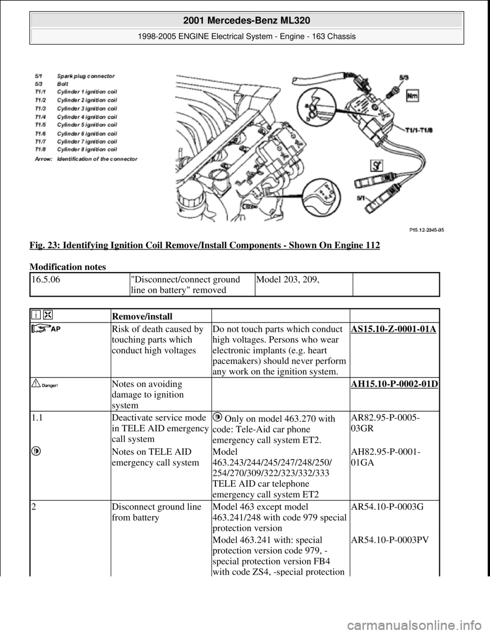
Fig. 23: Identifying Ignition Coil Remove/Install Components - Shown On Engine 112
Modification notes
16.5.06"Disconnect/connect ground
line on battery" removedModel 203, 209,
Remove/install
Risk of death caused by
touching parts which
conduct high voltagesDo not touch parts which conduct
high voltages. Persons who wear
electronic implants (e.g. heart
pacemakers) should never perform
any work on the ignition system.AS15.10-Z-0001-01A
Notes on avoiding
damage to ignition
system AH15.10-P-0002-01D
1.1Deactivate service mode
in TELE AID emergency
call system Only on model 463.270 with
code: Tele-Aid car phone
emergency call system ET2.AR82.95-P-0005-
03GR
Notes on TELE AID
emergency call systemModel
463.243/244/245/247/248/250/
254/270/309/322/323/332/333
TELE AID car telephone
emergency call system ET2AH82.95-P-0001-
01GA
2Disconnect ground line
from batteryModel 463 except model
463.241/248 with code 979 special
protection versionAR54.10-P-0003G
Model 463.241 with: special
protection version code 979, -
special protection version FB4
with code ZS4, -special protection AR54.10-P-0003PV
2001 Mercedes-Benz ML320
1998-2005 ENGINE Electrical System - Engine - 163 Chassis
me
Saturday, October 02, 2010 3:18:54 PMPage 38 © 2006 Mitchell Repair Information Company, LLC.
Page 2193 of 4133
version FB6 with code ZS6, -
special protection version FB7
with code ZS7, additional battery
100 Ah incl. cutoff relay code E26.
Model 463.248 with: special
protection version, code 979, -
special protection version FB6,
code ZS6, -special protection
version FB7, code ZS7, -additional
battery 100 Ah including cutoff
relay, code E26.AR54.10-P-0003PM
3.1Unclip cover on front
side of engineModel 211, 215, 220, 230.475/476
4.1Remove engine cover
with integrated air filterExcept model 170.466,
203.065/076/265/276, 209.376/476
from 24.4.04, 211.076/276,
215.374, 220.074/174, 230.474,
463.270/271
The air filter is integrated in the
engine cover. Remove the engine
cover or the air filter housing by
pulling it from the cylinder head
covers vertically in the upward
direction.
4.2Remove air filter housingModel 170.466, 203.065/265,
211.076/276, 215.374,
220.074/174, 230.474AR09.10-P-1150SVK
Model 203.076 /276, 209.376 /476
from 24.4.04, 171.473AR09.10-P-1150AC
Model 463.270/271AR09.10-P-1150GX
5Unscrew screw (5/3) *BA15.10-P-1001-
04A
6Detach spark plug
connector (5/1) from the
spark plugs Pry off spark plug connector
(5/1) using open-end wrench,
double over the cylinder head
cover of the spark plugs.
Installation: Observe the
identification of the connector
(arrow) on the cylinder head cover
and the ignition coil of cylinders 1
to 6 or 1 to 8 for the corresponding
spark plug connector (5/1).
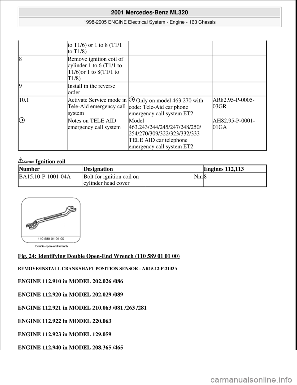
Double open-ended wrenchFig. 24
7Separate electrical
connector of ignition coil
of cylinder 1 to 6 (T1/1 Installation: Install new cable
ties.
2001 Mercedes-Benz ML320
1998-2005 ENGINE Electrical System - Engine - 163 Chassis
me
Saturday, October 02, 2010 3:18:54 PMPage 39 © 2006 Mitchell Repair Information Company, LLC.
Page 2194 of 4133
Ignition coil
Fig. 24: Identifying Double Open
-End Wrench (110 589 01 01 00)
REMOVE/INSTALL CRANKSHAFT POSITION SENSOR - AR15.12-P-2133A
ENGINE 112.910 in MODEL 202.026 /086
ENGINE 112.920 in MODEL 202.029 /089
ENGINE 112.921 in MODEL 210.063 /081 /263 /281
ENGINE 112.922 in MODEL 220.063
ENGINE 112.923 in MODEL 129.059
ENGINE 112.940 in MODEL 208.365 /465
to T1/6) or 1 to 8 (T1/1
to T1/8)
8Remove ignition coil of
cylinder 1 to 6 (T1/1 to
T1/6)or 1 to 8(T1/1 to
T1/8)
9Install in the reverse
order
10.1Activate Service mode in
Tele-Aid emergency call
system Only on model 463.270 with
code: Tele-Aid car phone
emergency call system ET2.AR82.95-P-0005-
03GR
Notes on TELE AID
emergency call systemModel
463.243/244/245/247/248/250/
254/270/309/322/323/332/333
TELE AID car telephone
emergency call system ET2AH82.95-P-0001-
01GA
NumberDesignationEngines 112,113
BA15.10-P-1001-04ABolt for ignition coil on
cylinder head coverNm8
2001 Mercedes-Benz ML320
1998-2005 ENGINE Electrical System - Engine - 163 Chassis
me
Saturday, October 02, 2010 3:18:54 PMPage 40 © 2006 Mitchell Repair Information Company, LLC.
Page 2203 of 4133
Parts ordering notes
REMOVE AND INSTALLING THE STARTER - AR15.30-P-7100GH
ENGINE 112.942 in MODEL 163.154
Removing and installing
1Remove air cleaner, install. Only on engine 119
2Expose wiring harness to
mass air flow sensor or
temperature sensor. Ignition switched
off
3Unplug socket from mass
air flow sensor or
temperature sensor.
4Plug in repair socket
together with cables at
mass air flow sensor or
temperature sensor and
insert into cable duct.
5Repair wiring harness
using end soldering sleeves
(Z). Turn together cable of
engine wiring harness and
cable repair socket of the
same color and insert into
end soldered sleeves (Z).
Use end soldered
sleeves (Z) only in cross
section area Ø 0.7 - Ø 4.0
mm
2
AR54.18-P-0100-02A
6Insert cables into the cable
duct.
7Connect HHT, read faults
and erase see Diagnosis Manual
Engine Volume 2 Index 0:
Connecting and using test
equipment
8Install in the reverse order
Part no.DesignationQuantity
140 540 00 36Repair kit socket (B2)1
1) Consisting of repair socket (B2)
and 5 cable connectorsacc. to condition
140 540 00 81Repair socket (B2)acc. to condition
202 540 01 81Repair socket (B11) 3-pinacc. to condition
126 540 30 81Repair socket (B11) 4-pinacc. to condition
001 546 99 41Cable connectoracc. to condition
006 989 84 85Fabric tapeacc. to condition
2001 Mercedes-Benz ML320
1998-2005 ENGINE Electrical System - Engine - 163 Chassis
me
Saturday, October 02, 2010 3:18:54 PMPage 49 © 2006 Mitchell Repair Information Company, LLC.
Page 2207 of 4133
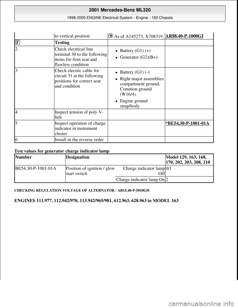
Test values for generator charge indicator lamp
CHECKING REGULATION VOLTAGE OF ALTERNATOR - AR15.40-P-5010GH
ENGINES 111.977, 112.942/970, 113.942/965/981, 612.963, 628.963 in MODEL 163
to vertical position As of A145273, X708319.AR88.40-P-1000GI
Testing
2Check electrical line
terminal 30 to the following
items for firm seat and
flawless conditionBattery (G1) (+)
Generator (G2)(B+)
3Check electric cable for
circuit 31 at the following
positions for correct seat
and conditionBattery (G1) (-)
Right major assemblies
compartment ground,
Common ground
(W16/4)
Engine ground
strap/body
4Inspect tension of poly V-
belt
5Inspect operation of charge
indicator in instrument
cluster *BE54.30-P-1001-01A
6Install in the reverse order
NumberDesignationModel 129, 163, 168,
170, 202, 203, 208, 210
BE54.30-P-1001-01APosition of ignition / glow
start switchCharge indicator lamp
Of
f
0/1
Charge indicator lamp On2
2001 Mercedes-Benz ML320
1998-2005 ENGINE Electrical System - Engine - 163 Chassis
me
Saturday, October 02, 2010 3:18:54 PMPage 53 © 2006 Mitchell Repair Information Company, LLC.
Page 2226 of 4133
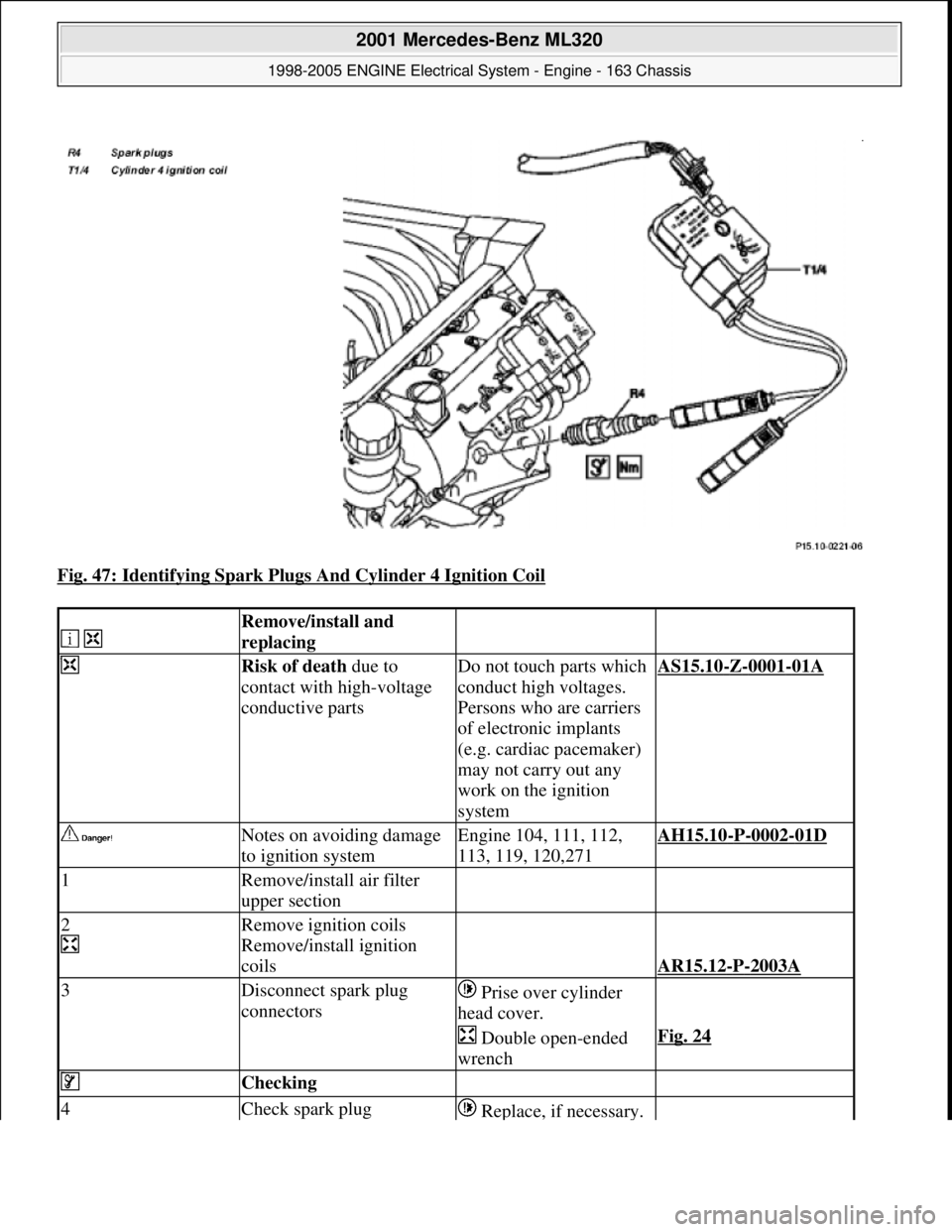
Fig. 47: Identifying Spark Plugs And Cylinder 4 Ignition Coil
Remove/install and
replacing
Risk of death due to
contact with high-voltage
conductive partsDo not touch parts which
conduct high voltages.
Persons who are carriers
of electronic implants
(e.g. cardiac pacemaker)
may not carry out any
work on the ignition
systemAS15.10-Z-0001-01A
Notes on avoiding damage
to ignition systemEngine 104, 111, 112,
113, 119, 120,271AH15.10-P-0002-01D
1Remove/install air filter
upper section
2
Remove ignition coils
Remove/install ignition
coils
AR15.12-P-2003A
3Disconnect spark plug
connectors Prise over cylinder
head cover.
Double open-ended
wrenchFig. 24
Checking
4Check spark plug Replace, if necessary.
2001 Mercedes-Benz ML320
1998-2005 ENGINE Electrical System - Engine - 163 Chassis
me
Saturday, October 02, 2010 3:18:55 PMPage 72 © 2006 Mitchell Repair Information Company, LLC.
Page 2227 of 4133
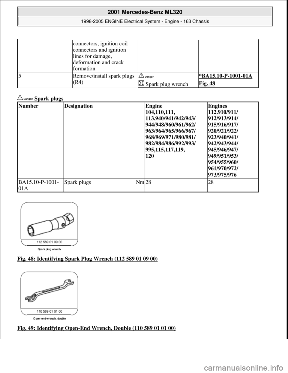
Spark plugs
Fig. 48: Identifying Spark Plug Wrench (112 589 01 09 00)
Fig. 49: Identifying Open
-End Wrench, Double (110 589 01 01 00)
connectors, ignition coil
connectors and ignition
lines for damage,
deformation and crack
formation
5Remove/install spark plugs
(R4) *BA15.10-P-1001-01A
Spark plug wrenchFig. 48
NumberDesignationEngine
104,110,111,
113.940/941/942/943/
944/948/960/961/962/
963/964/965/966/967/
968/969/971/980/981/
982/984/986/992/993/
995,115,117,119,
120Engines
112.910/911/
912/913/914/
915/916/917/
920/921/922/
923/940/941/
942/943/944/
945/946/947/
949/951/953/
954/955/960/
961/970/972/
973/975/976
BA15.10-P-1001-
01ASpark plugsNm2828
2001 Mercedes-Benz ML320
1998-2005 ENGINE Electrical System - Engine - 163 Chassis
me
Saturday, October 02, 2010 3:18:55 PMPage 73 © 2006 Mitchell Repair Information Company, LLC.
Page 2236 of 4133

GF00.20-P-2009A
Engine oil monitor function
24.10.96
MODEL
129 with ENGINE 112, 113
MODEL
163 with ENGINE 112, 113, 612
MODEL
168 with ENGINE 166, 668
MODEL
202 with ENGINE 112, 611
MODEL
208 up to 31.7.99 with ENGINE 112, 113
MODEL
210 up to 30.6.99 with ENGINE 112, 113, 611
General
The oil level is constantly monitored by the oil sensor, and the
appropriate data transmitted to the processor by the ASSYST.
Oil replenishments are detected automatically and result in a bonus,
which extends the service interval accordingly.
An excess oil level or insufficient oil level appears in the display
together with the oil can symbol.
Display of low oil level at maximum:
D
at driver request
Display of warnings: D
automatically, at the earliest 60 s after engine start and oil
temperature greater than 60°C:
D
if oil level too high: the oil can symbol appears together
with the readout "OIL LEVEL ABOVE MAX". In addition, a
brief warning signal sounds. (On models not fitted with
multifunction displaly, "HI" appears flashing.)
D
if oil level too low: the oil can symbol appears together with
the readout "OIL LEVEL BELOW MIN". In addition, a brief
warning signal sounds. (On models not fitted with multifunction
display, the oil level warning lamp (A1e12) comes on and the
readout "-2L" appears flashing.)
-----------------------------------------------------------------------------------------
D
if oil at minimum: the oil can symbol appears together with
the readout "OIL LEVEL MINIMUM". In addition, a brief
warning signal sounds. (On models not fitted with multifunction
display, the oil level warning lamp (A1e12) comes on.)
D
automatically 13 s after ignition ON:
D
if
no oil
is in engine: the oil can symbol appears together
with the readout "OIL LEVEL BELOW MIN". In addition, a
warning signal sounds. (On models not fitted with multifunction
display, the oil level warning lamp (A1e12) comes on and the
readout "-2L"appears flashing. In addition a brief warning
signal sounds.)
The missing oil quantity displayed no longer changes during the
display. In other words, any change in oil level cannot be observed
directly at the display. The new oil level is only displayed once the
conditions described below exist.
Display of oil quantity at driver request
The text "DISPLAY OIL LEVEL?" appears 10 s after the start switch
has been turned into position "2" (on models not fitted with
multifunction display, the oil can and the clock symbol are displayed).
If the reset button of the trip counter is pressed twice within one sec.
during this readout, for example, "add 1.0L oil" (or "-1.0L")
-----------------------------------------------------------------------------------------
appears in the display if oil level too low. The readout appears only
after the elapse of a waiting time after engine OFF. The waiting time
depends on the engine oil temperature.
It is
D
up to 20°C
30 minutes
D
from 60°C
1 minute
D
The waiting time is between these two limits at other engine oil
temperatures.
Possible readouts are (text in parenthesis relates to models not fitted
with multifunction display.):
D
"OIL LEVEL OKAY" ("o.k."),
D
1.0L, 1.5L, 2L,
D
"Overfilling" ("HI"),
D
"OBSERVE WAITING TIME" (clock symbol flashing and oil can
symbol),
D
"DISPLAY OIL LEVEL" (clock and oil can symbols.)
If there is a fault at the oil sensor (oil level/temperature/quality, B40)
the oil can symbol and the text "OIL LEVEL SENSOR FAULTY"
appears only 30 s after the fault has occurred.
(On models not fitted with multifunction display, the oil level warning
lamp (A1e12) comes on accordingly.)
For diagnosis, read also the injection system control module (N3)
with the HHT. (The instrument cluster (A1) receives the sensor data
through the CAN from the injection system control module (N3)).
-----------------------------------------------------------------------------------------
Oil change
The ASSYST has to be reset each time the oil is changed. Resetting
ASSYST also resets the remaining time and the remaining distance.
Resetting can be performed at the instrument cluster or using the
HHT.
The following data are stored when the system is reset:
D
current kilometer reading rounded off to 100,
D
total oil replenishments in the last interval,
D
remaining distance,
D
remaining time,
D
product of the quality factors,
D
the data of the last 5 resettings in 5 data sets
These data can only be read with the HHT!
If the specified quantity of oil is not replenished when the oil is
changed, the (internal) start distance is reduced.
Detecting oil replenishments
D
With the
HHT
it is possible to retrieve the last 10 oil
replenishments and the corresponding kilometer readings of
the current interval.
D
In the normal case, detection of an oil replenishment is
displayed by the remaining distance in the instrument cluster
being extended
-----------------------------------------------------------------------------------------
Copyright DaimlerChrysler AG 05.06.2006 CD-Ausgabe G/10/04 . This WIS print-out will not be recorde
d by Modification services.
Page 1