1997 MERCEDES-BENZ ML320 clock
[x] Cancel search: clockPage 2105 of 4133

GF54.30-P-2002A
Display instruments, location / task / function
24.10.96
MODEL
129, 140 as of 1.6.96,
163, 168, 170,
202 as of 1.8.96,
208 up to 31.7.99,
210 as of 1.6.96 up to 30.6.99
Display
Type of data transmission
D
Outside temperature indicator (A1p4)
D
Fuel level gauge (A1p2)
D
Engine oil pressure gauge (A1p3), only
model 129 and model 140
D
Low windshield washer fluid level
indicator lamp (A1e13), model 163 as of
01.09.01
Direct lines
GF54.30-P-3004A
D
Total mileage odometer (A1h4)
D
Electronic speedometer (A1p8)
D
Tachometer (A1p5)
D
Coolant temperature gauge (A1p1)
D
Active service system (ASSYST)
D
Gear indicator (A1p12), only model 168
CAN data lines
GF54.30-P-3005A
D
Electronic clock
Internal
GF54.30-P-3011A
Copyright DaimlerChrysler AG 04.06.2006 CD-Ausgabe G/10/04 . This WIS print-out will not be recorde
d by Modification services.
Page 1
Page 2106 of 4133

AD54.30-P-3000-03A
Display instruments/multi-function display
function check IC
Display
instruments
The display instruments must indicate according to operating
conditions.
Phototransistor (models 202, 208, 210)
Point a beam of light at the phototransistor with a pocket lamp, the
display illumination of the LCD displays (outside temperature, trip
odometer, total mileage recorder and electronic clock) must get
brighter.
Instrument cluster with multi-function display
If there are malfunctions (e.g. brake linings worn, coolant level too
low, exterior lamp failure etc.) or system faults (anti-lock brake
system faulty, supplemental restraint system faulty) the warning
display with warning information is inserted in place of outside
temperature, odometer, total mileage recorder and electronic clock.
The warning information is displayed in yellow or red depending on
the fault and a warning tone also sounds.
Copyright DaimlerChrysler AG 05.06.2006 CD-Ausgabe G/10/04 . This WIS print-out will not be recorde
d by Modification services.
Page 1
Page 2228 of 4133
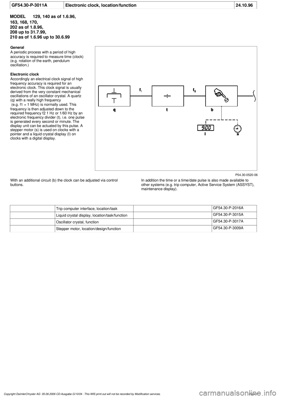
GF54.30-P-3011A
Electronic clock, location/function
24.10.96
MODEL
129, 140 as of 1.6.96,
163, 168, 170,
202 as of 1.8.96,
208 up to 31.7.99,
210 as of 1.6.96 up to 30.6.99
P54.30-0520-06
General
A periodic process with a period of high
accuracy is required to measure time (clock)
(e.g. rotation of the earth, pendulum
oscillation.)
Electronic clock
Accordingly an electrical clock signal of high
frequency accuracy is required for an
electronic clock. This clock signal is usually
derived from the very constant mechanical
oscillations of an oscillator crystal. A quartz
(q) with a really high frequency
(e.g. f
1
= 1 MHz) is normally used. This
frequency is then adjusted down to the
required frequency f
2
1 Hz or 1/60 Hz by an
electronic frequency divider (t), i.e. one pulse
is generated every second or minute. The
display unit can be actuated by this pulse. A
stepper motor (s) is used on clocks with a
pointer and a liquid crystal display (I) on
clocks with a digital display.
With an additional circuit (b) the clock can be adjusted via control
buttons.
In addition the time or a time/date pulse is also made available to
other systems (e.g. trip computer, Active Service System (ASSYST),
maintenance display).
Trip computer interface, location/task
GF54.30-P-2016A
Liquid crystal display, location/task/function
GF54.30-P-3015A
Oscillator crystal, function
GF54.30-P-3017A
Stepper motor, location/design/function
GF54.30-P-3009A
Copyright DaimlerChrysler AG 05.06.2006 CD-Ausgabe G/10/04 . This WIS print-out will not be recorde
d by Modification services.
Page 1
Page 2236 of 4133

GF00.20-P-2009A
Engine oil monitor function
24.10.96
MODEL
129 with ENGINE 112, 113
MODEL
163 with ENGINE 112, 113, 612
MODEL
168 with ENGINE 166, 668
MODEL
202 with ENGINE 112, 611
MODEL
208 up to 31.7.99 with ENGINE 112, 113
MODEL
210 up to 30.6.99 with ENGINE 112, 113, 611
General
The oil level is constantly monitored by the oil sensor, and the
appropriate data transmitted to the processor by the ASSYST.
Oil replenishments are detected automatically and result in a bonus,
which extends the service interval accordingly.
An excess oil level or insufficient oil level appears in the display
together with the oil can symbol.
Display of low oil level at maximum:
D
at driver request
Display of warnings: D
automatically, at the earliest 60 s after engine start and oil
temperature greater than 60°C:
D
if oil level too high: the oil can symbol appears together
with the readout "OIL LEVEL ABOVE MAX". In addition, a
brief warning signal sounds. (On models not fitted with
multifunction displaly, "HI" appears flashing.)
D
if oil level too low: the oil can symbol appears together with
the readout "OIL LEVEL BELOW MIN". In addition, a brief
warning signal sounds. (On models not fitted with multifunction
display, the oil level warning lamp (A1e12) comes on and the
readout "-2L" appears flashing.)
-----------------------------------------------------------------------------------------
D
if oil at minimum: the oil can symbol appears together with
the readout "OIL LEVEL MINIMUM". In addition, a brief
warning signal sounds. (On models not fitted with multifunction
display, the oil level warning lamp (A1e12) comes on.)
D
automatically 13 s after ignition ON:
D
if
no oil
is in engine: the oil can symbol appears together
with the readout "OIL LEVEL BELOW MIN". In addition, a
warning signal sounds. (On models not fitted with multifunction
display, the oil level warning lamp (A1e12) comes on and the
readout "-2L"appears flashing. In addition a brief warning
signal sounds.)
The missing oil quantity displayed no longer changes during the
display. In other words, any change in oil level cannot be observed
directly at the display. The new oil level is only displayed once the
conditions described below exist.
Display of oil quantity at driver request
The text "DISPLAY OIL LEVEL?" appears 10 s after the start switch
has been turned into position "2" (on models not fitted with
multifunction display, the oil can and the clock symbol are displayed).
If the reset button of the trip counter is pressed twice within one sec.
during this readout, for example, "add 1.0L oil" (or "-1.0L")
-----------------------------------------------------------------------------------------
appears in the display if oil level too low. The readout appears only
after the elapse of a waiting time after engine OFF. The waiting time
depends on the engine oil temperature.
It is
D
up to 20°C
30 minutes
D
from 60°C
1 minute
D
The waiting time is between these two limits at other engine oil
temperatures.
Possible readouts are (text in parenthesis relates to models not fitted
with multifunction display.):
D
"OIL LEVEL OKAY" ("o.k."),
D
1.0L, 1.5L, 2L,
D
"Overfilling" ("HI"),
D
"OBSERVE WAITING TIME" (clock symbol flashing and oil can
symbol),
D
"DISPLAY OIL LEVEL" (clock and oil can symbols.)
If there is a fault at the oil sensor (oil level/temperature/quality, B40)
the oil can symbol and the text "OIL LEVEL SENSOR FAULTY"
appears only 30 s after the fault has occurred.
(On models not fitted with multifunction display, the oil level warning
lamp (A1e12) comes on accordingly.)
For diagnosis, read also the injection system control module (N3)
with the HHT. (The instrument cluster (A1) receives the sensor data
through the CAN from the injection system control module (N3)).
-----------------------------------------------------------------------------------------
Oil change
The ASSYST has to be reset each time the oil is changed. Resetting
ASSYST also resets the remaining time and the remaining distance.
Resetting can be performed at the instrument cluster or using the
HHT.
The following data are stored when the system is reset:
D
current kilometer reading rounded off to 100,
D
total oil replenishments in the last interval,
D
remaining distance,
D
remaining time,
D
product of the quality factors,
D
the data of the last 5 resettings in 5 data sets
These data can only be read with the HHT!
If the specified quantity of oil is not replenished when the oil is
changed, the (internal) start distance is reduced.
Detecting oil replenishments
D
With the
HHT
it is possible to retrieve the last 10 oil
replenishments and the corresponding kilometer readings of
the current interval.
D
In the normal case, detection of an oil replenishment is
displayed by the remaining distance in the instrument cluster
being extended
-----------------------------------------------------------------------------------------
Copyright DaimlerChrysler AG 05.06.2006 CD-Ausgabe G/10/04 . This WIS print-out will not be recorde
d by Modification services.
Page 1
Page 2396 of 4133
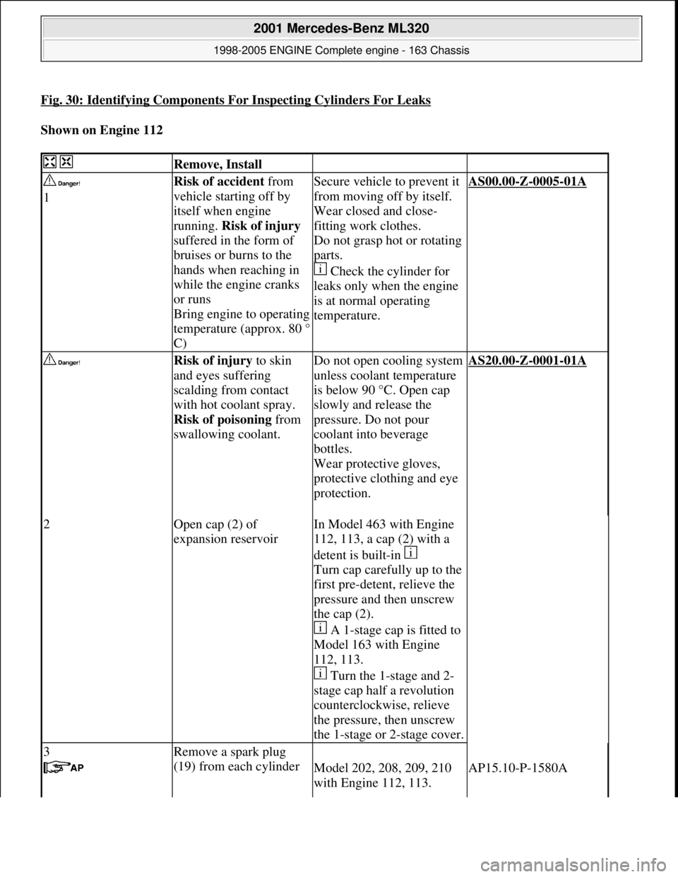
Fig. 30: Identifying Components For Inspecting Cylinders For Leaks
Shown on Engine 112
Remove, Install
1Risk of accident from
vehicle starting off by
itself when engine
running. Risk of injury
suffered in the form of
bruises or burns to the
hands when reaching in
while the engine cranks
or runs
Bring engine to operating
temperature (approx. 80 °
C)Secure vehicle to prevent it
from moving off by itself.
Wear closed and close-
fitting work clothes.
Do not grasp hot or rotating
parts.
Check the cylinder for
leaks only when the engine
is at normal operating
temperature.AS00.00-Z-0005-01A
Risk of injury to skin
and eyes suffering
scalding from contact
with hot coolant spray.
Risk of poisoning from
swallowing coolant.
Do not open cooling system
unless coolant temperature
is below 90 °C. Open cap
slowly and release the
pressure. Do not pour
coolant into beverage
bottles.
Wear protective gloves,
protective clothing and eye
protection.
AS20.00-Z-0001-01A
2Open cap (2) of
expansion reservoirIn Model 463 with Engine
112, 113, a cap (2) with a
detent is built-in
Turn cap carefully up to the
first pre-detent, relieve the
pressure and then unscrew
the cap (2).
A 1-stage cap is fitted to
Model 163 with Engine
112, 113.
Turn the 1-stage and 2-
stage cap half a revolution
counterclockwise, relieve
the pressure, then unscrew
the 1-stage or 2-stage cover.
3Remove a spark plug
(19) from each cylinder
Model 202, 208, 209, 210
with Engine 112, 113.AP15.10-P-1580A
2001 Mercedes-Benz ML320
1998-2005 ENGINE Complete engine - 163 Chassis
me
Saturday, October 02, 2010 3:17:56 PMPage 40 © 2006 Mitchell Repair Information Company, LLC.
Page 2440 of 4133
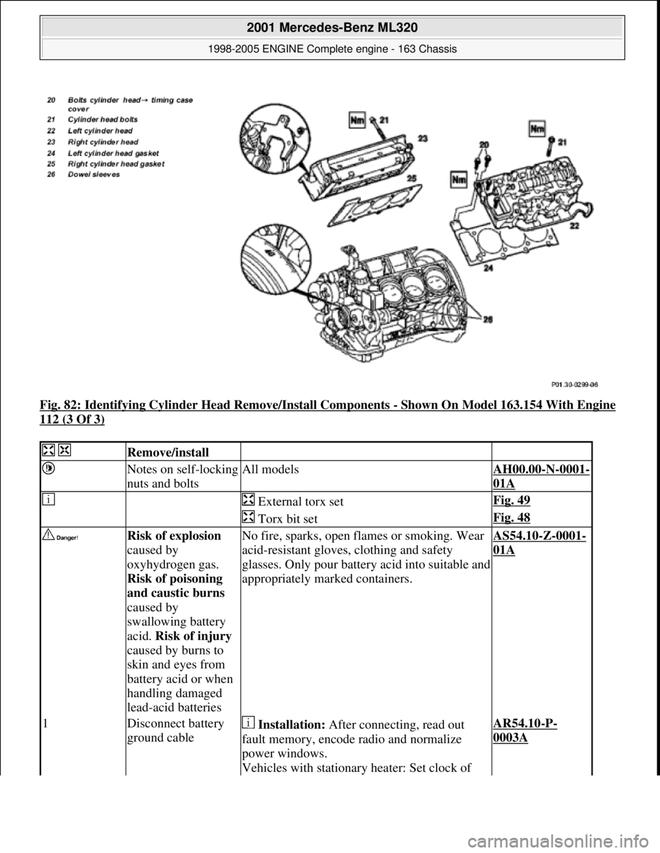
Fig. 82: Identifying Cylinder Head Remove/Install Components - Shown On Model 163.154 With Engine
112 (3 Of 3)
Remove/install
Notes on self-locking
nuts and boltsAll modelsAH00.00-N-0001-
01A
External torx setFig. 49
Torx bit setFig. 48
Risk of explosion
caused by
oxyhydrogen gas.
Risk of poisoning
and caustic burns
caused by
swallowing battery
acid. Risk of injury
caused by burns to
skin and eyes from
battery acid or when
handling damaged
lead-acid batteriesNo fire, sparks, open fl ames or smoking. Wear
acid-resistant gloves, clothing and safety
glasses. Only pour batter y acid into suitable and
appropriately marked containers.AS54.10-Z-0001-
01A
1Disconnect battery
ground cable Installation: After connecting, read out
fault memory, encode radio and normalize
power windows.
Vehicles with stationary heater: Set clock of AR54.10-P-
0003A
2001 Mercedes-Benz ML320
1998-2005 ENGINE Complete engine - 163 Chassis
me
Saturday, October 02, 2010 3:17:57 PMPage 84 © 2006 Mitchell Repair Information Company, LLC.
Page 2516 of 4133
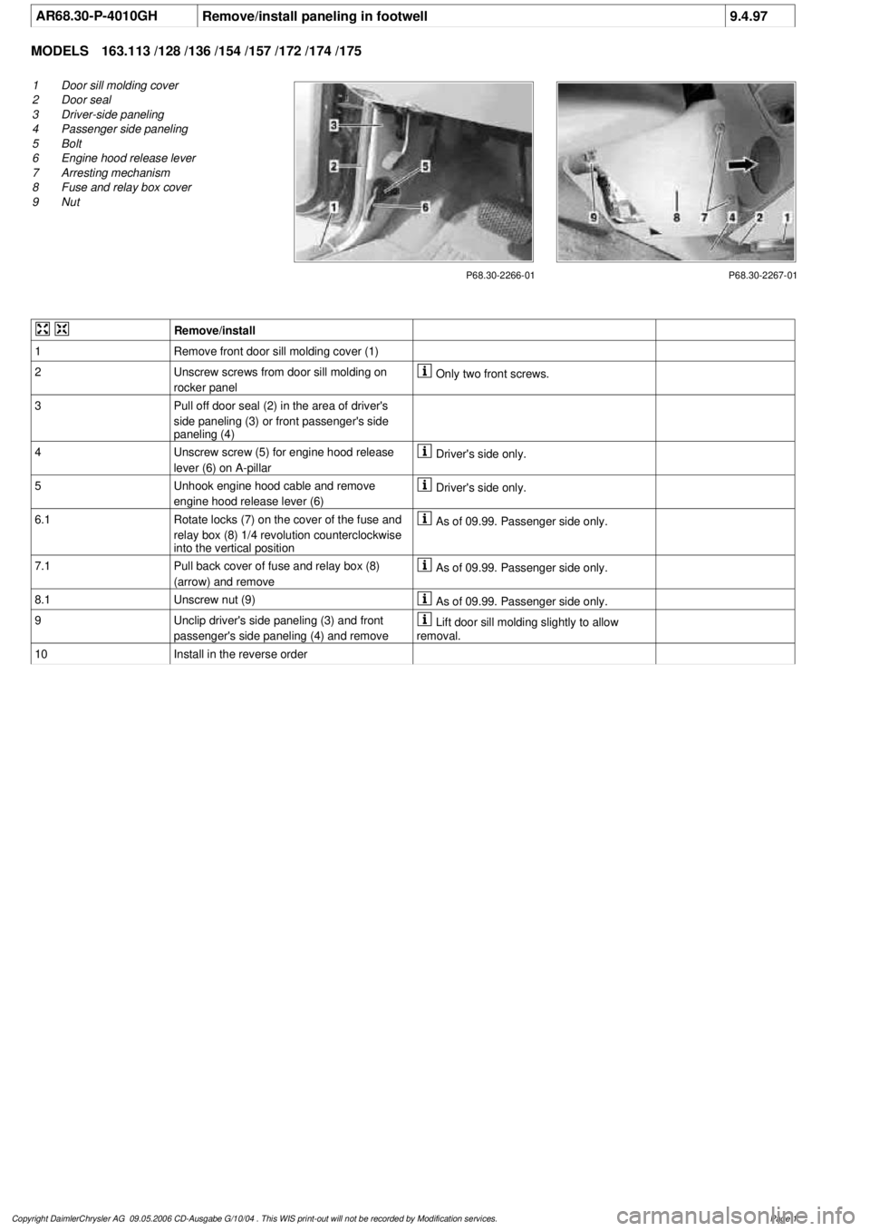
AR68.30-P-4010GHRemove/install paneling in footwell
9.4.97
MODELS
163.113 /128 /136 /154 /157 /172 /174 /175
P68.30-2266-01
1
Door sill molding cover
2
Door seal
3
Driver-side paneling
4
Passenger side paneling
5
Bolt
6
Engine hood release lever
7
Arresting mechanism
8
Fuse and relay box cover
9
Nut
P68.30-2267-01
Remove/install
1
Remove front door sill molding cover (1)
2
Unscrew screws from door sill molding on
rocker panel
Only two front screws.
3
Pull off door seal (2) in the area of driver's
side paneling (3) or front passenger's side
paneling (4)
4
Unscrew screw (5) for engine hood release
lever (6) on A-pillar
Driver's side only.
5
Unhook engine hood cable and remove
engine hood release lever (6)
Driver's side only.
6.1
Rotate locks (7) on the cover of the fuse and
relay box (8) 1/4 revolution counterclockwise
into the vertical position
As of 09.99. Passenger side only.
7.1
Pull back cover of fuse and relay box (8)
(arrow) and remove
As of 09.99. Passenger side only.
8.1
Unscrew nut (9)
As of 09.99. Passenger side only.
9
Unclip driver's side paneling (3) and front
passenger's side paneling (4) and remove
Lift door sill molding slightly to allow
removal.
10
Install in the reverse order
Copyright DaimlerChrysler AG 09.05.2006 CD-Ausgabe G/10/04 . This WIS print-out will not be recorde
d by Modification services.
Page 1
Page 2524 of 4133
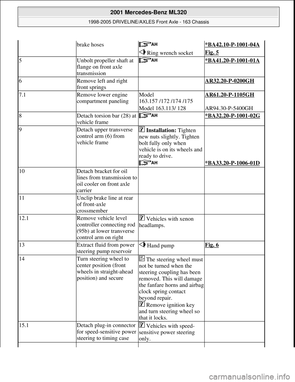
brake hoses *BA42.10-P-1001-04A
Ring wrench socketFig. 5
5Unbolt propeller shaft at
flange on front axle
transmission *BA41.20-P-1001-01A
6Remove left and right
front springs AR32.20-P-0200GH
7.1Remove lower engine
compartment panelingModel
163.157 /172 /174 /175AR61.20-P-1105GH
Model 163.113/ 128AR94.30-P-5400GH
8Detach torsion bar (28) at
vehicle frame *BA32.20-P-1001-02G
9Detach upper transverse
control arm (6) from
vehicle frame Installation: Tighten
new nuts slightly. Tighten
bolt fully only when
vehicle is on its wheels and
ready to drive.
*BA33.20-P-1006-01D
10Detach bracket for oil
lines from transmission to
oil cooler on front axle
carrier
11Unclip brake line at rear
of front-axle
crossmember
12.1Remove vehicle level
controller connecting rod
(95b) at lower transverse
control arm on right Vehicles with xenon
headlamps.
13Extract fluid from power
steering pump reservoir Hand pumpFig. 6
14Turn steering wheel to
center position (front
wheels in straight-ahead
position) and secureThe steering wheel must
not be turned when the
steering coupling has been
removed. This will damage
the fanfare horns and airbag
clock spring contact
beyond repair.
Remove ignition key
and turn steering wheel so
that it locks.
15.1Detach plug-in connector
for speed-sensitive power
steering to timing case Vehicles with speed-
sensitive power steering
only.
2001 Mercedes-Benz ML320
1998-2005 DRIVELINE/AXLES Front Axle - 163 Chassis
me
Saturday, October 02, 2010 3:38:21 PMPage 5 © 2006 Mitchell Repair Information Company, LLC.