Page 3404 of 4133

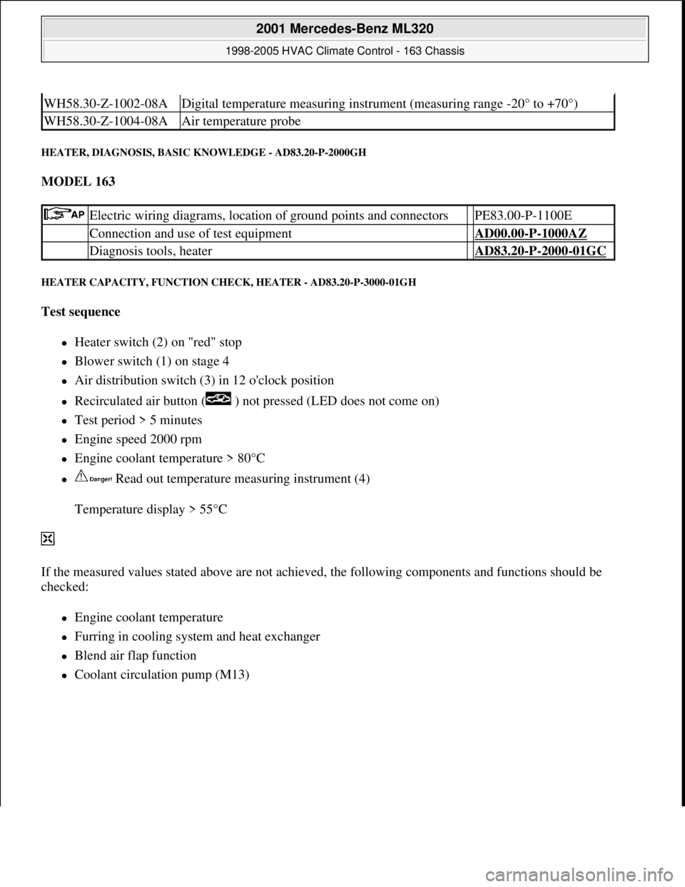
HEATER, DIAGNOSIS, BASIC KNOWLEDGE - AD83.20-P-2000GH
MODEL 163
HEATER CAPACITY, FUNCTION CHECK, HEATER - AD83.20-P-3000-01GH
Test sequence
Heater switch (2) on "red" stop
Blower switch (1) on stage 4
Air distribution switch (3) in 12 o'clock position
Recirculated air button ( ) not pressed (LED does not come on)
Test period > 5 minutes
Engine speed 2000 rpm
Engine coolant temperature > 80°C
Read out temperature measuring instrument (4)
Temperature display > 55°C
If the measured values stated above are not achieved, the following components and functions should be
checked:
Engine coolant temperature
Furring in cooling system and heat exchanger
Blend air flap function
Coolant circulation pump (M13)
WH58.30-Z-1002-08ADigital temperature measuring instrument (measuring range -20° to +70°)
WH58.30-Z-1004-08AAir temperature probe
Electric wiring diagrams, location of ground points and connectors PE83.00-P-1100E
Connection and use of test equipment AD00.00-P-1000AZ
Diagnosis tools, heater AD83.20-P-2000-01GC
2001 Mercedes-Benz ML320
1998-2005 HVAC Climate Control - 163 Chassis
me
Saturday, October 02, 2010 3:23:17 PMPage 160 © 2006 Mitchell Repair Information Company, LLC.
Page 3412 of 4133

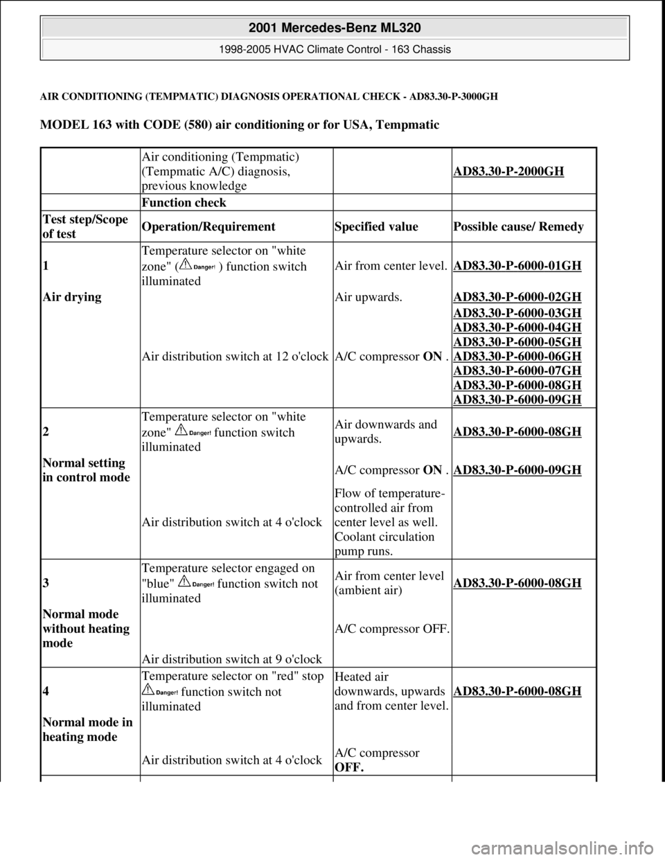
AIR CONDITIONING (TEMPMATIC) DIAGNOSIS OPERATIONAL CHECK - AD83.30-P-3000GH
MODEL 163 with CODE (580) air conditioning or for USA, Tempmatic
Air conditioning (Tempmatic)
(Tempmatic A/C) diagnosis,
previous knowledge
AD83.30-P-2000GH
Function check
Test step/Scope
of test Operation/Requirement Specified value Possible cause/ Remedy
1
Temperature selector on "white
zone" ( ) function switch
illuminated
Air from center level.AD83.30-P-6000-01GH
Air drying Air upwards.AD83.30-P-6000-02GH
Air distribution switch at 12 o'clockA/C compressor ON .
AD83.30-P-6000-03GH
AD83.30
-P-6000-04GH
AD83.30
-P-6000-05GH
AD83.30
-P-6000-06GH
AD83.30
-P-6000-07GH
AD83.30
-P-6000-08GH
AD83.30
-P-6000-09GH
2
Temperature selector on "white
zone" function switch
illuminatedAir downwards and
upwards.AD83.30-P-6000-08GH
Normal setting
in control mode A/C compressor ON .AD83.30-P-6000-09GH
Air distribution switch at 4 o'clock
Flow of temperature-
controlled air from
center level as well.
Coolant circulation
pump runs.
3
Temperature selector engaged on
"blue" function switch not
illuminatedAir from center level
(ambient air)AD83.30-P-6000-08GH
Normal mode
without heating
mode
A/C compressor OFF.
Air distribution switch at 9 o'clock
4
Temperature selector on "red" stop
function switch not
illuminatedHeated air
downwards, upwards
and from center level.
AD83.30-P-6000-08GH
Normal mode in
heating mode
Air distribution switch at 4 o'clockA/C compressor
OFF.
2001 Mercedes-Benz ML320
1998-2005 HVAC Climate Control - 163 Chassis
me
Saturday, October 02, 2010 3:23:17 PMPage 168 © 2006 Mitchell Repair Information Company, LLC.
Page 3461 of 4133
Fig. 174: Identifying Air Conditioning Control Module Components
REMOVE AND INSTALL EVAPORATOR TEMPERATURE SENSOR - AR83.30-P-8085GH
MODEL 163 with CODE (580) Air conditioning or Tempmatic for USA
Fig. 175: Identifying Evaporator Temperature Sensor Components
Removal, installation
1Disconnect ground cable of battery AR54.10-P-0003A
2Remove switch unit for heater/ ventilation (1) AR83.20-P-
1835GH
3Unscrew bolt (4) for air conditioning control module (N19) at
evaporator housing (3)
4Disconnect connector (5) at air conditioning control module (N19)
5Detach air conditioning control module (N19) from evaporator
housing (3)
6Install in the reverse order
7Encode radio AR82.60-P-7502-
01GH
8Read out diagnostic trouble code memory, erase and set clock
2001 Mercedes-Benz ML320
1998-2005 HVAC Climate Control - 163 Chassis
me
Saturday, October 02, 2010 3:23:19 PMPage 217 © 2006 Mitchell Repair Information Company, LLC.
Page 3466 of 4133

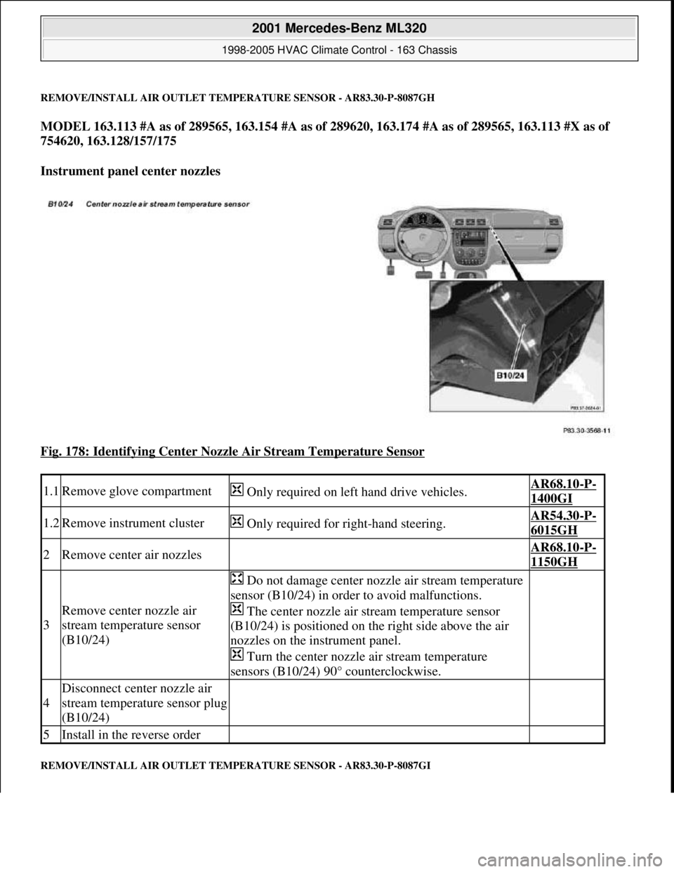
REMOVE/INSTALL AIR OUTLET TEMPERATURE SENSOR - AR83.30-P-8087GH
MODEL 163.113 #A as of 289565, 163.154 #A as of 289620, 163.174 #A as of 289565, 163.113 #X as of
754620, 163.128/157/175
Instrument panel center nozzles
Fig. 178: Identifying Center Nozzle Air Stream Temperature Sensor
REMOVE/INSTALL AIR OUTLET TEMPERATURE SENSOR - AR83.30-P-8087GI
1.1Remove glove compartment Only required on left hand drive vehicles.AR68.10-P-
1400GI
1.2Remove instrument cluster Only required for right-hand steering.AR54.30-P-
6015GH
2Remove center air nozzles AR68.10-P-
1150GH
3
Remove center nozzle air
stream temperature sensor
(B10/24)
Do not damage center nozzle air stream temperature
sensor (B10/24) in order to avoid malfunctions.
The center nozzle air stream temperature sensor
(B10/24) is positioned on the right side above the air
nozzles on the instrument panel.
Turn the center nozzle air stream temperature
sensors (B10/24) 90° counterclockwise.
4
Disconnect center nozzle air
stream temperature sensor plug
(B10/24)
5Install in the reverse order
2001 Mercedes-Benz ML320
1998-2005 HVAC Climate Control - 163 Chassis
me
Saturday, October 02, 2010 3:23:19 PMPage 222 © 2006 Mitchell Repair Information Company, LLC.
Page 3467 of 4133
MODEL 163.113 /154 /174 #A as of 289565, 163.113 #X as of 754620, 163.128/157/175
Driver's side footwell
Fig. 179: Identifying Front Footwell Air Stream Temperature Sensor
REMOVE/INSTALL AIR OUTLET TEMPERATURE SENSOR - AR83.30-P-8087GJ
MODEL 163.113 /154 /174 #A as of 289565, 163.113 #X as of 754620, 163.128/157/175
Blower motor in rear
Remove/install
1Remove cover below instrument
panel AR68.10-P-
1500GH
2
Disconnect plug from front footwell
air stream temperature sensor
(B10/25)
3Remove front footwell air stream
temperature sensor(B10/25)
Do not damage front footwell air
stream temperature sensor (B10/25).
Turn front footwell air stream
temperature sensor (B10/25) 90
counterclockwise.
4Install in the reverse order
2001 Mercedes-Benz ML320
1998-2005 HVAC Climate Control - 163 Chassis
me
Saturday, October 02, 2010 3:23:19 PMPage 223 © 2006 Mitchell Repair Information Company, LLC.
Page 3468 of 4133
Fig. 180: Identifying Rear Air Stream Temperature Sensor And Connector
REMOVE, INSTALL IN-CAR TEMPERATURE SENSOR FOR ASPIRATOR BLOWER (M9) - AR83.30-P-8100GH
MODELS 163.113/136/154/172/174 as of 1.9.99 up to 31.8.01
Remove/install
1Remove center console AR68.20-P-
2000GH
2Remove sound deadener
3
Disconnect plug (1) from rear
air stream temperature sensor
(B10/7) The rear air stream temperature sensor
(B10/7) is positioned in the left air nozzle on
the blower motor.
4Remove rear air stream
temperature sensor (B10/7)
Do not damage rear air stream temperature
sensor (B10/7).
Turn rear air stream temperature sensor
(B10/7) 90 counterclockwise.
5Install in the reverse order
2001 Mercedes-Benz ML320
1998-2005 HVAC Climate Control - 163 Chassis
me
Saturday, October 02, 2010 3:23:19 PMPage 224 © 2006 Mitchell Repair Information Company, LLC.
Page 3491 of 4133
AR54.30-P-6031GH
Removing and installing instrument cluster housing
21.1.97
MODEL
163
P54.30-0631-06
1
Cover
2
Instrument cluster housing
3
Symbol strip
Removing, installing
1
Remove instrument cluster
AR54.30-P-6015GH
2
Unclip retaining lugs (arrows)
Installation:
The retaining lugs must lock
fully in position.
3
Remove cover (1) from instrument cluster
housing (2)
The symbol strips (3) may fall out sideways.
Installation:
Pay attention to vehicle equipment when
replacing symbol strips.
Ensure the adjusting knobs for the odometer
and electronic clock are seated correctly.
4
Install in reverse order
Copyright DaimlerChrysler AG 09.05.2006 CD-Ausgabe G/10/04 . This WIS print-out will not be recorde
d by Modification services.
Page 1
Page 3503 of 4133

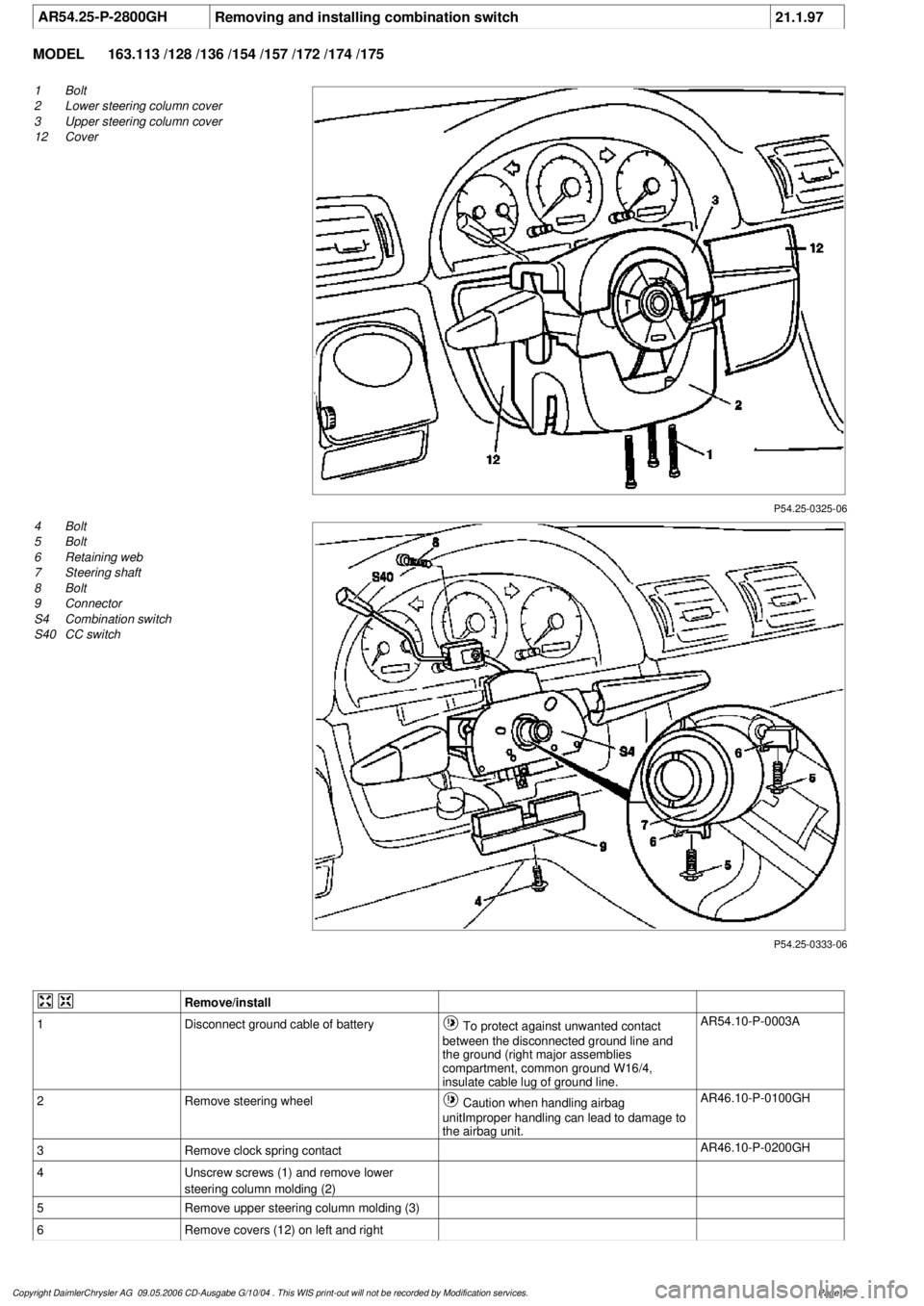
AR54.25-P-2800GH
Removing and installing combination switch
21.1.97
MODEL
163.113 /128 /136 /154 /157 /172 /174 /175
P54.25-0325-06
1
Bolt
2
Lower steering column cover
3
Upper steering column cover
12
Cover
P54.25-0333-06
4
Bolt
5
Bolt
6
Retaining web
7
Steering shaft
8
Bolt
9
Connector
S4
Combination switch
S40
CC switch
Remove/install
1
Disconnect ground cable of battery
To protect against unwanted contact
between the disconnected ground line and
the ground (right major assemblies
compartment, common ground W16/4,
insulate cable lug of ground line.
AR54.10-P-0003A
2
Remove steering wheel
Caution when handling airbag
unitImproper handling can lead to damage to
the airbag unit.
AR46.10-P-0100GH
3
Remove clock spring contact
AR46.10-P-0200GH
4
Unscrew screws (1) and remove lower
steering column molding (2)
5
Remove upper steering column molding (3)
6
Remove covers (12) on left and right
Copyright DaimlerChrysler AG 09.05.2006 CD-Ausgabe G/10/04 . This WIS print-out will not be recorde
d by Modification services.
Page 1