1997 MERCEDES-BENZ ML320 clock
[x] Cancel search: clockPage 3576 of 4133
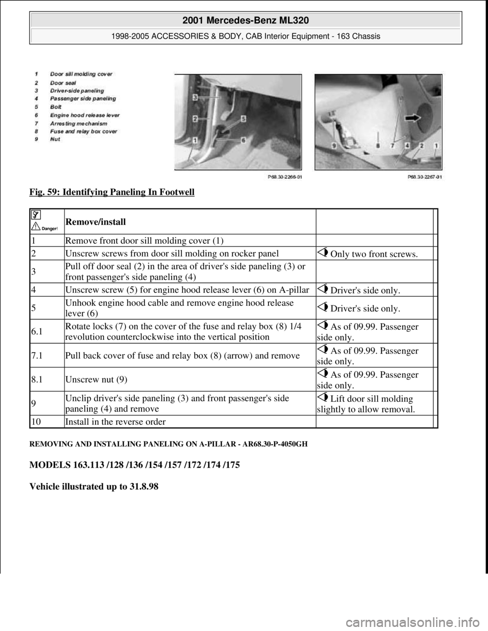
Fig. 59: Identifying Paneling In Footwell
REMOVING AND INSTALLING PANELING ON A-PILLAR - AR68.30-P-4050GH
MODELS 163.113 /128 /136 /154 /157 /172 /174 /175
Vehicle illustrated up to 31.8.98
Remove/install
1Remove front door sill molding cover (1)
2Unscrew screws from door sill molding on rocker panel Only two front screws.
3Pull off door seal (2) in the area of driver's side paneling (3) or
front passenger's side paneling (4)
4Unscrew screw (5) for engine hood release lever (6) on A-pillar Driver's side only.
5Unhook engine hood cable and remove engine hood release
lever (6) Driver's side only.
6.1Rotate locks (7) on the cover of the fuse and relay box (8) 1/4
revolution counterclockwise into the vertical position As of 09.99. Passenger
side only.
7.1Pull back cover of fuse and relay box (8) (arrow) and remove As of 09.99. Passenger
side only.
8.1Unscrew nut (9) As of 09.99. Passenger
side only.
9Unclip driver's side paneling (3) and front passenger's side
paneling (4) and remove Lift door sill molding
slightly to allow removal.
10Install in the reverse order
2001 Mercedes-Benz ML320
1998-2005 ACCESSORIES & BODY, CAB Interior Equipment - 163 Chassis
me
Saturday, October 02, 2010 3:35:22 PMPage 58 © 2006 Mitchell Repair Information Company, LLC.
Page 3588 of 4133
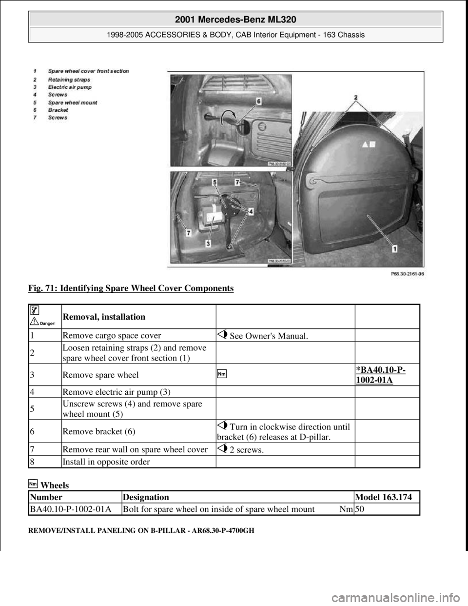
Fig. 71: Identifying Spare Wheel Cover Components
Wheels
REMOVE/INSTALL PANELING ON B-PILLAR - AR68.30-P-4700GH
Removal, installation
1Remove cargo space cover See Owner's Manual.
2Loosen retaining straps (2) and remove
spare wheel cover front section (1)
3Remove spare wheel *BA40.10-P-
1002-01A
4Remove electric air pump (3)
5Unscrew screws (4) and remove spare
wheel mount (5)
6Remove bracket (6) Turn in clockwise direction until
bracket (6) releases at D-pillar.
7Remove rear wall on spare wheel cover 2 screws.
8Install in opposite order
NumberDesignationModel 163.174
BA40.10-P-1002-01ABolt for spare wheel on inside of spare wheel mountNm50
2001 Mercedes-Benz ML320
1998-2005 ACCESSORIES & BODY, CAB Interior Equipment - 163 Chassis
me
Saturday, October 02, 2010 3:35:22 PMPage 70 © 2006 Mitchell Repair Information Company, LLC.
Page 3751 of 4133
GF54.30-P-3017A
Quartz, location/task/function
8.7.99
MODEL
129, 140 as of 1.6.96,
163, 168, 170,
202 as of 1.8.96,
208,
210 as of 1.6.96,
215, 220
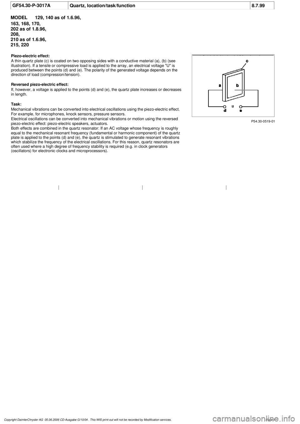
P54.30-0519-01
Piezo-electric effect:
A thin quartz plate (c) is coated on two opposing sides with a conductive material (a), (b) (see
illustration). If a tensile or compressive load is applied to the array, an electrical voltage "U" i
s
produced between the points (d) and (e). The polarity of the generated voltage depends on the
direction of load (compression/tension).
Reversed piezo-electric effect:
If, however, a voltage is applied to the points (d) and (e), the quartz plate increases or decreases
in length.
Task:
Mechanical vibrations can be converted into electrical oscillations using the piezo-electric effect.
For example, for microphones, knock sensors, pressure sensors.
Electrical oscillations can be converted into mechanical vibrations or motion using the reversed
piezo-electric effect: piezo-electric speakers, actuators.
Both effects are combined in the quartz resonator: If an AC voltage whose frequency is roughly
equal to the mechanical resonant frequency (fundamental or harmonic component) of the quartz
plate is applied to the points (d) and (e), the quartz is stimulated to generate resonant vibrations
which stabilize the frequency of the electrical oscillations. For this reason, quartz resonators are
often used where a high degree of frequency stability is required (e.g. in clock generators
(oscillators) for electronic clocks and microprocessors).
Copyright DaimlerChrysler AG 05.06.2006 CD-Ausgabe G/10/04 . This WIS print-out will not be recorde
d by Modification services.
Page 1
Page 3805 of 4133
AR91.12-P-1100GH
Remove and install cover on bottom of rear seat
22.2.00
MODELS
163.136 /154 /172 as of 1.9.99,
163.113 /128 /157 /174 /175
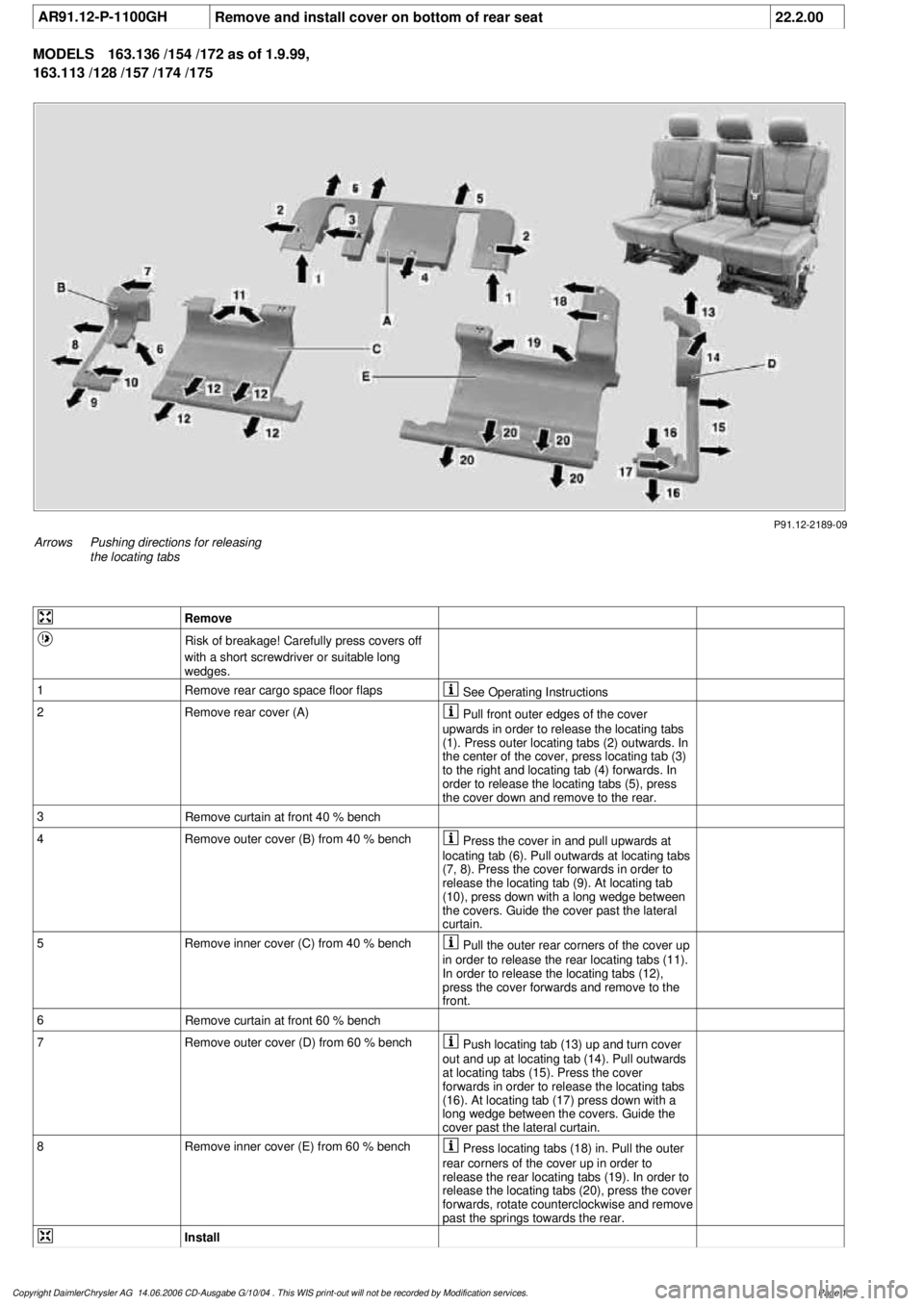
P91.12-2189-09
Arrows
Pushing directions for releasing
the locating tabs
Remove
Risk of breakage! Carefully press covers off
with a short screwdriver or suitable long
wedges.
1
Remove rear cargo space floor flaps
See Operating Instructions
2Remove rear cover (A)
Pull front outer edges of the cover
upwards in order to release the locating tabs
(1). Press outer locating tabs (2) outwards. In
the center of the cover, press locating tab (3)
to the right and locating tab (4) forwards. In
order to release the locating tabs (5), press
the cover down and remove to the rear.
3
Remove curtain at front 40 % bench
4
Remove outer cover (B) from 40 % bench
Press the cover in and pull upwards at
locating tab (6). Pull outwards at locating tabs
(7, 8). Press the cover forwards in order to
release the locating tab (9). At locating tab
(10), press down with a long wedge between
the covers. Guide the cover past the lateral
curtain.
5
Remove inner cover (C) from 40 % bench
Pull the outer rear corners of the cover up
in order to release the rear locating tabs (11).
In order to release the locating tabs (12),
press the cover forwards and remove to the
front.
6
Remove curtain at front 60 % bench
7
Remove outer cover (D) from 60 % bench
Push locating tab (13) up and turn cover
out and up at locating tab (14). Pull outwards
at locating tabs (15). Press the cover
forwards in order to release the locating tabs
(16). At locating tab (17) press down with a
long wedge between the covers. Guide the
cover past the lateral curtain.
8
Remove inner cover (E) from 60 % bench
Press locating tabs (18) in. Pull the outer
rear corners of the cover up in order to
release the rear locating tabs (19). In order to
release the locating tabs (20), press the cover
forwards, rotate counterclockwise and remove
past the springs towards the rear.
Install
Copyright DaimlerChrysler AG 14.06.2006 CD-Ausgabe G/10/04 . This WIS print-out will not be recorde
d by Modification services.
Page 1
Page 3806 of 4133

9
Install inner cover (E) at 60 % bench
Insert cover past the springs from the rear
and rotate into position in a clockwise
direction. Insert locating tabs (19). Press the
front cover down and reset so that locating
tabs (20) engage. Press rear cover down until
locating tabs (18) engage.
10
Install outer cover (D) at 60 % bench
Guide the cover past the lateral curtain.
Insert locating tab (17), push front cover down
and reset so that locating tabs (16) engage.
Press the outer edge of the cover down and
insert lateral locating tabs (15). Raise rear
cover on the inside, press down until locating
tab (14) and rear locating tab (13) engage.
11
Install curtain at front 60 % bench
12
Install inner cover (C) at 40 % bench
Insert cover from the front and insert
locating tabs (11). Press the front cover down
and reset so that locating tabs (12) engage.
13
Install outer cover (B) at 40 % bench
Guide the cover past the lateral curtain.
Insert locating tab (10), push front cover down
and reset so that locating tab (9) engages.
Press the outer edge of the cover down and
insert lateral locating tabs (8). Insert locating
tab (7), push cover down at locating tab (6)
and engage.
14
Install curtain at front 40 % bench
15
Install rear cover (A)
Insert cover from the rear and press down
and forwards so that locating tabs (5) engage.
Press front ends of the cover down, so that
locating tabs (2, 3, 4) engage. Insert locating
tabs (1) into covers (C, E).
Copyright DaimlerChrysler AG 14.06.2006 CD-Ausgabe G/10/04 . This WIS print-out will not be recorde
d by Modification services.
Page 2
Page 3811 of 4133
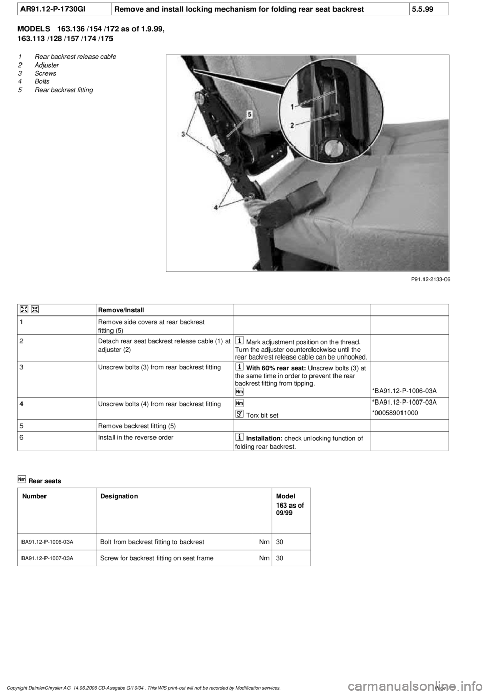
AR91.12-P-1730GI
Remove and install locking mechanism for folding rear seat backrest
5.5.99
MODELS
163.136 /154 /172 as of 1.9.99,
163.113 /128 /157 /174 /175
P91.12-2133-06
1
Rear backrest release cable
2
Adjuster
3
Screws
4
Bolts
5
Rear backrest fitting
Remove/Install
1
Remove side covers at rear backrest
fitting (5)
2
Detach rear seat backrest release cable (1) at
adjuster (2)
Mark adjustment position on the thread.
Turn the adjuster counterclockwise until the
rear backrest release cable can be unhooked.
3
Unscrew bolts (3) from rear backrest fitting
With 60% rear seat:
Unscrew bolts (3) at
the same time in order to prevent the rear
backrest fitting from tipping.
*BA91.12-P-1006-03A
4
Unscrew bolts (4) from rear backrest fitting
*BA91.12-P-1007-03A
Torx bit set
*000589011000
5
Remove backrest fitting (5)
6
Install in the reverse order
Installation:
check unlocking function of
folding rear backrest.
Rear seats
Number
Designation
Model
163 as of
09/99
BA91.12-P-1006-03A
Bolt from backrest fitting to backrest
Nm
30
BA91.12-P-1007-03A
Screw for backrest fitting on seat frame
Nm
30
Copyright DaimlerChrysler AG 14.06.2006 CD-Ausgabe G/10/04 . This WIS print-out will not be recorde
d by Modification services.
Page 1
Page 3838 of 4133
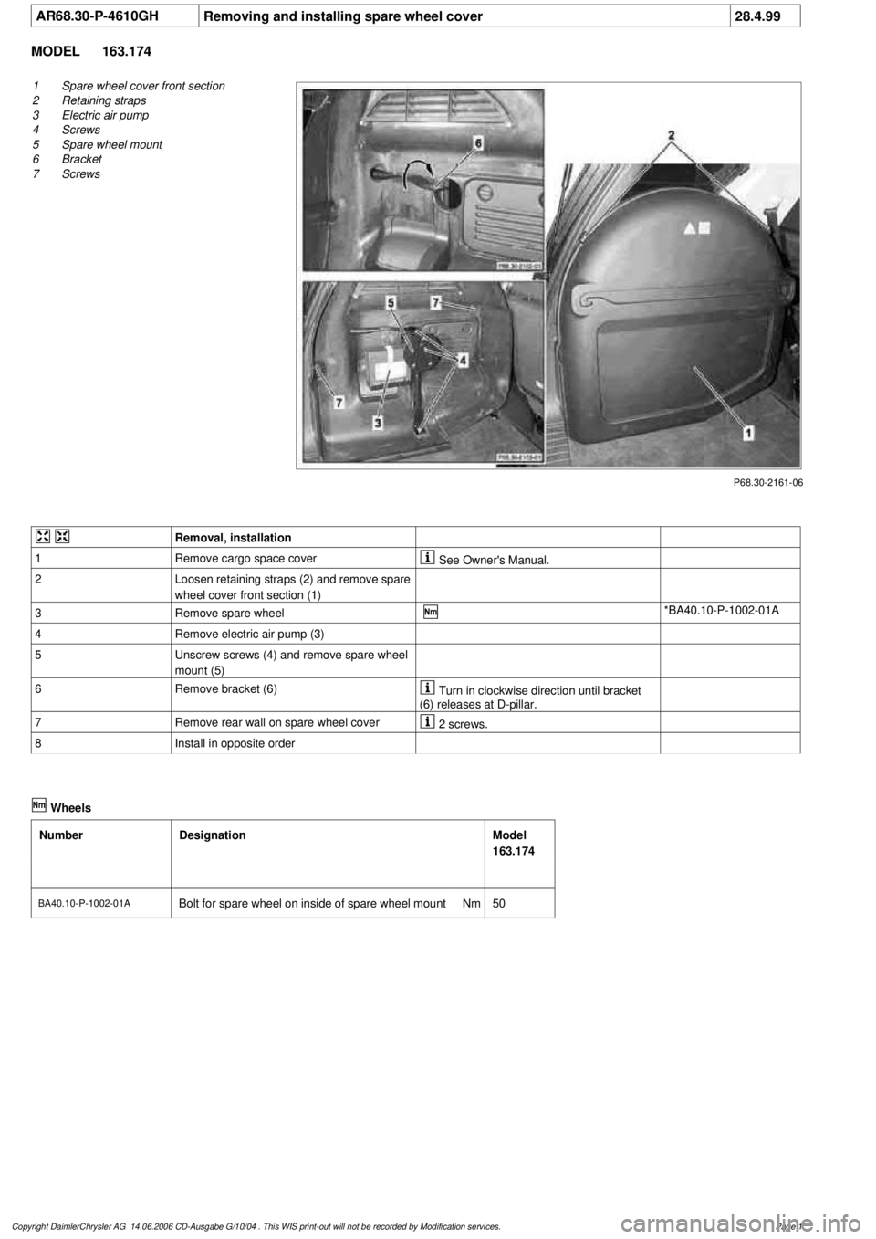
AR68.30-P-4610GH
Removing and installing spare wheel cover
28.4.99
MODEL
163.174
P68.30-2161-06
1
Spare wheel cover front section
2
Retaining straps
3
Electric air pump
4
Screws
5
Spare wheel mount
6
Bracket
7
Screws
Removal, installation
1
Remove cargo space cover
See Owner's Manual.
2
Loosen retaining straps (2) and remove spare
wheel cover front section (1)
3
Remove spare wheel
*BA40.10-P-1002-01A
4
Remove electric air pump (3)
5
Unscrew screws (4) and remove spare wheel
mount (5)
6
Remove bracket (6)
Turn in clockwise direction until bracket
(6) releases at D-pillar.
7
Remove rear wall on spare wheel cover
2 screws.
8
Install in opposite order
Wheels
Number
Designation
Model
163.174
BA40.10-P-1002-01A
Bolt for spare wheel on inside of spare wheel mount
Nm
50
Copyright DaimlerChrysler AG 14.06.2006 CD-Ausgabe G/10/04 . This WIS print-out will not be recorde
d by Modification services.
Page 1
Page 3839 of 4133
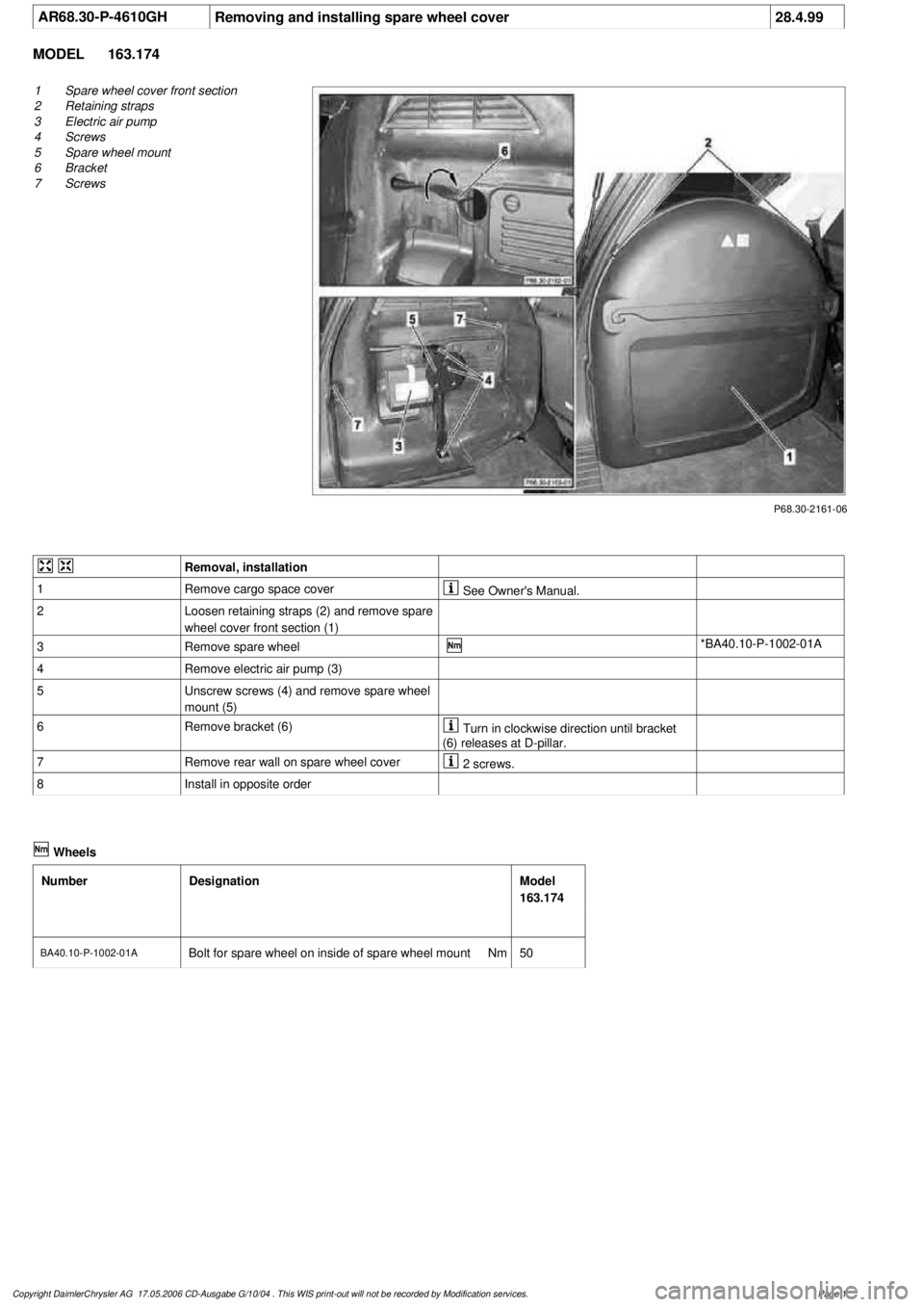
AR68.30-P-4610GH
Removing and installing spare wheel cover
28.4.99
MODEL
163.174
P68.30-2161-06
1
Spare wheel cover front section
2
Retaining straps
3
Electric air pump
4
Screws
5
Spare wheel mount
6
Bracket
7
Screws
Removal, installation
1
Remove cargo space cover
See Owner's Manual.
2
Loosen retaining straps (2) and remove spare
wheel cover front section (1)
3
Remove spare wheel
*BA40.10-P-1002-01A
4
Remove electric air pump (3)
5
Unscrew screws (4) and remove spare wheel
mount (5)
6
Remove bracket (6)
Turn in clockwise direction until bracket
(6) releases at D-pillar.
7
Remove rear wall on spare wheel cover
2 screws.
8
Install in opposite order
Wheels
Number
Designation
Model
163.174
BA40.10-P-1002-01A
Bolt for spare wheel on inside of spare wheel mount
Nm
50
Copyright DaimlerChrysler AG 17.05.2006 CD-Ausgabe G/10/04 . This WIS print-out will not be recorde
d by Modification services.
Page 1