1997 MERCEDES-BENZ ML320 clock
[x] Cancel search: clockPage 2840 of 4133
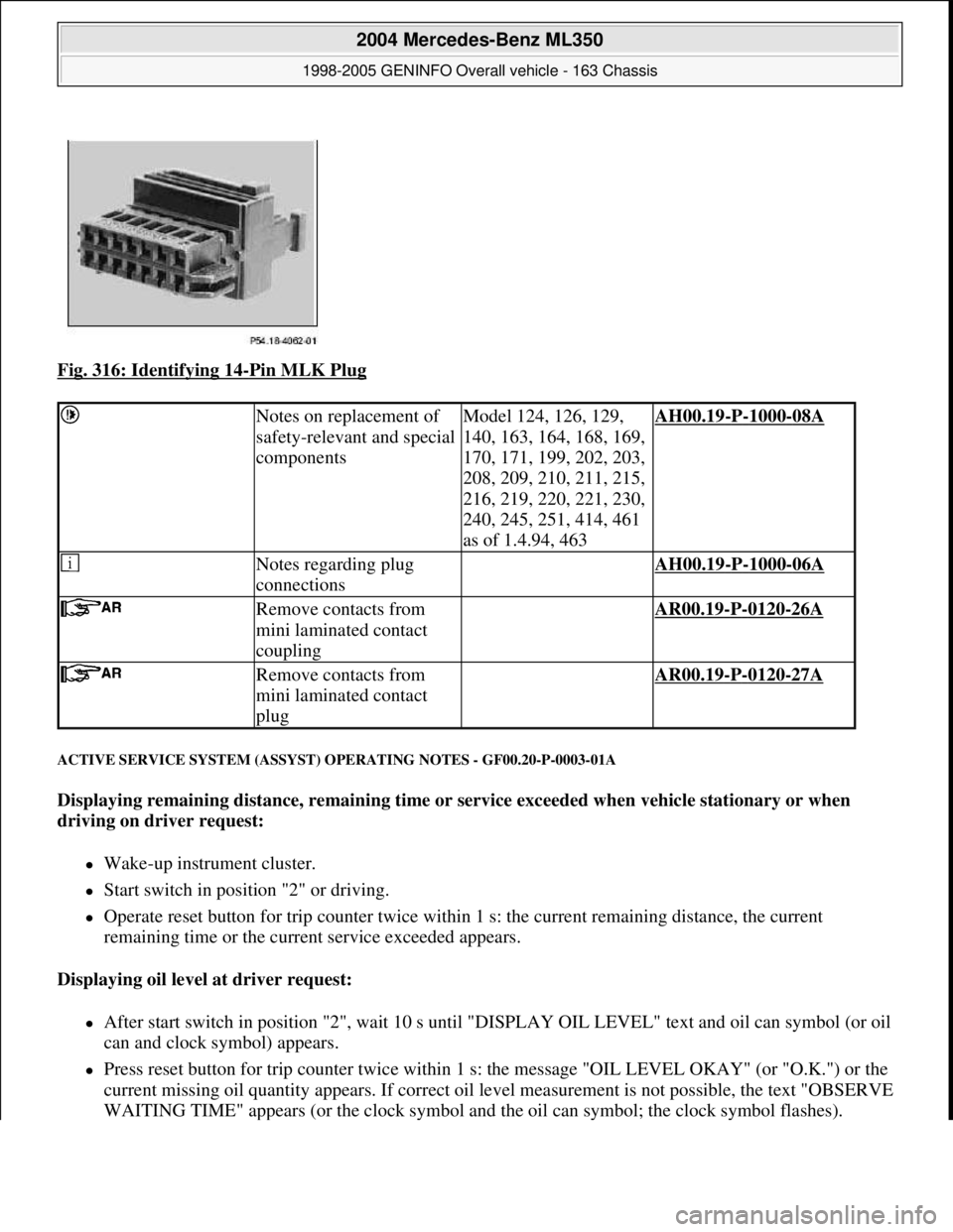
Fig. 316: Identifying 14-Pin MLK Plug
ACTIVE SERVICE SYSTEM (ASSYST) OPERATING NOTES - GF00.20-P-0003-01A
Displaying remaining distance, remaining time or service exceeded when vehicle stationary or when
driving on driver request:
Wake-up instrument cluster.
Start switch in position "2" or driving.
Operate reset button for trip counter twice within 1 s: the current remaining distance, the current
remaining time or the current service exceeded appears.
Displaying oil level at driver request:
After start switch in position "2", wait 10 s until "DISPLAY OIL LEVEL" text and oil can symbol (or oil
can and clock symbol) appears.
Press reset button for trip counter twice within 1 s: the message "OIL LEVEL OKAY" (or "O.K.") or the
current missing oil quantity appears. If correct oil level measurement is not possible, the text "OBSERVE
WAITING TIME" appears (or the clock s
ymbol and the oil can symbol; the clock symbol flashes).
Notes on replacement of
safety-relevant and special
componentsModel 124, 126, 129,
140, 163, 164, 168, 169,
170, 171, 199, 202, 203,
208, 209, 210, 211, 215,
216, 219, 220, 221, 230,
240, 245, 251, 414, 461
as of 1.4.94, 463AH00.19-P-1000-08A
Notes regarding plug
connections AH00.19-P-1000-06A
Remove contacts from
mini laminated contact
coupling AR00.19-P-0120-26A
Remove contacts from
mini laminated contact
plug AR00.19-P-0120-27A
2004 Mercedes-Benz ML350
1998-2005 GENINFO Overall vehicle - 163 Chassis
me
Saturday, October 02, 2010 3:47:47 PMPage 195 © 2006 Mitchell Repair Information Company, LLC.
Page 2843 of 4133
Engine version factor (gasoline/diesel)
National factor (The kilometer or mileage is coded in accordance with the national version.)
Distance travelled :
ASSYST is supplied with the 4 wheel speeds from the traction systems control module (N47) over the
CAN for calculating the distance travelled.
Time
ASSYST is supplied with the time information from the clock integrated in the instrument cluster.
ACTIVE SERVICE SYSTEM (ASSYST) SURVEY MODEL/ENGINE/SENSOR/INSTRUMENT CLUSTER - GF00.20-P-0003-
06A
The table below (status: March 1999) lists the various vehicle models with the different engines and the
different oil level sensors.
In addition, the table also indicates whether an instrument cluster with multifunction display is fitted.
ModelEngineOil level sensorMultifunction display
with engine
129112, 113
103, 104, 119, 120Oil sensor (oil
level/temperature/quality, B40)
Oil level indicator switch S43-
140-
104, 119, 120, 606Oil sensor (oil
level/temperature/quality, B40)
Oil level indicator switch S43-
163112, 113, 612
111Oil sensor (oil
level/temperature/quality, B40)
Oil level indicator switch S43-
168166, 668
-Oil sensor (oil
level/temperature/quality, B40)
Oil level indicator switch S43-
170112
111Oil sensor (oil
level/temperature/quality, B40)
Oil level indicator switch S43-
202112, 113, 611
104, 111, 601, 604,
605Oil sensor (oil
level/temperature/quality, B40)
Oil level indicator switch S43-
208112, 113
111Oil sensor (oil
level/temperature/quality, B40)
Oil level indicator switch S43Engine 112 only and
Gulf States: engine 111
210112, 113, 611
104, 111, 602, 605,
606Oil sensor (oil
level/temperature/quality, B40)Engines 112,113 Gulf
States, , : on all
engines fitted; others:
2004 Mercedes-Benz ML350
1998-2005 GENINFO Overall vehicle - 163 Chassis
me
Saturday, October 02, 2010 3:47:47 PMPage 198 © 2006 Mitchell Repair Information Company, LLC.
Page 2845 of 4133
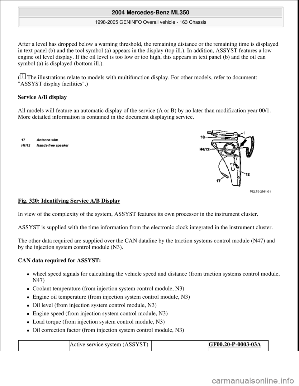
After a level has dropped below a warning threshold, the remaining distance or the remaining time is displayed
in text panel (b) and the tool symbol (a) appears in the display (top ill.). In addition, ASSYST features a low
engine oil level display. If the oil level is too low or too high, this appears in text panel (b) and the oil can
symbol (a) is displayed (bottom ill.).
( The illustrations relate to models with multifunction display. For other models, refer to document:
"ASSYST display facilities".)
Service A/B display
All models will feature an automatic display of the service (A or B) by no later than modification year 00/1.
More detailed information is contained in the document displaying service.
Fig. 320: Identifying Service A/B Display
In view of the complexity of the system, ASSYST features its own processor in the instrument cluster.
ASSYST is supplied with the time information from the electronic clock integrated in the instrument cluster.
The other data required are supplied over the CAN dataline by the traction systems control module (N47) and
by the injection system control module (N3).
CAN data required for ASSYST:
wheel speed signals for calculating the vehicle speed and distance (from traction systems control module,
N47)
Coolant temperature (from injection system control module, N3)
Engine oil temperature (from injection system control module, N3)
Oil level (from injection system control module, N3)
Engine speed (from injection system control module, N3)
Load torque (from injection system control module, N3)
Oil correction factor (from injection system control module, N3)
Active service system (ASSYST) GF00.20-P-0003-03A
2004 Mercedes-Benz ML350
1998-2005 GENINFO Overall vehicle - 163 Chassis
me
Saturday, October 02, 2010 3:47:47 PMPage 200 © 2006 Mitchell Repair Information Company, LLC.
Page 2853 of 4133
Warning threshold (in days)
With the HHT it is possible to set a warning threshold of between 5 and 30 days for the remaining time, with a
stepwidth of one day. The basic setting is 30 days.
Display of remaining time
The remaining time is always only displayed in those cases where the following condition is met:
Remaining time (in days) x 40 < remaining distance (in km), and the warning threshold is reached.
The remaining time is displayed in the following cases:
automatically, after 5 s start switch in position 2 or driving, if the warning threshold is reached:
The service symbol and the readout "SERVICE IN ... DAYS" appears for 10 seconds. (On vehicles not
fitted with multifunction display, the current remaining time, the service and the clock symbol appear.)
automatically, after 5 s start switch in position 2 or driving, if the remaining time is exceeded:
The service symbol and the readout "DAYS ... EXCEEDED" appears for 30 s (for 10 s up to mid-July
97). (On vehicles not fitted with multifunction display, the service and the clock symbol appear. The
"remaining time" is displayed with a negative sign (minus sign). The readout flashes in this case.)
After the display reaches the maximum readout of -730 days, the readout remains at this figure! The
readout is displayed with a resolution of 1 day.
As of approx. 06.97 a brief warning signal sounds in addition.
at driver request. The readout is then displayed, as above, for 10 s.
If a speed limit is set at the cruise control, this speed limit is displayed for a short moment before the
ASSYST display.
If certain measured values are not supplied to the ASSYST, e.g. because of failure of a sensor, it switches to
stored substitute values. An appropriate entry is then made in the fault memory of the particular control module.
If the power supply fails, the data are retained. The times without operating voltage (battery disconnected) are
not recorded, however! They can be retroactively included, however, with the HHT.
Active service system
(ASSYST) operating
informationEngine with oil sensor
(e.g. 112, 113, 611)GF00.20-P-0003-01A
Model 210 as of 01.03.97
with engines 111, 602,
604, 605, 606
Model 129, 140, 170, 202 GF00.20-P-0003-01B
2004 Mercedes-Benz ML350
1998-2005 GENINFO Overall vehicle - 163 Chassis
me
Saturday, October 02, 2010 3:47:47 PMPage 208 © 2006 Mitchell Repair Information Company, LLC.
Page 2855 of 4133
An excess oil level or insufficient oil level appears in the display together with the oil can symbol.
Display of low oil level at maximum:
at driver request
Display of warnings:
automatically, at the earliest 60s after engine start and oil temperature greater than 60°C:
if oil level too high: the oil can symbol appears together with the readout "OIL LEVEL ABOVE
MAX". In addition, a brief warning signal sounds. (On models not fitted with multifunction
display, "HI" appears flashing.)
if oil level too low: the oil can symbol appears together with the readout "OIL LEVEL BELOW
MIN". In addition, a brief warning signal sounds. (On models not fitted with multifunction display,
the oil level warning lamp (A1e12) comes on and the readout "-2L" appears flashing.)
if oil at minimum: the oil can symbol appears together with the readout "OIL LEVEL MINIMUM".
In addition, a brief warning signal sounds. (On models not fitted with multifunction display, the oil
level warning lamp (A1e12) comes on.)
automatically 13 s after ignition ON:
if no oil is in engine: the oil can symbol appears together with the readout "OIL LEVEL BELOW
MIN". In addition, a warning signal sounds. (On models not fitted with multifunction display, the
oil level warning lamp (A1e12) comes on and the readout "-2L" appears flashing. In addition a
brief warning signal sounds.)
The missing oil quantity displayed no longer changes during the display. In other words, any change in oil level
cannot be observed directly at the display. The new oil level is only displayed once the conditions described
below exist.
Display of oil quantity at driver request
The text "DISPLAY OIL LEVEL?" appears 10 s after the start switch has been turned into position "2" (on
models not fitted with multifunction display, the oil can and the clock symbol are displayed).
If the reset button of the trip counter is pressed twice within one sec. during this readout, for example, "add 1.0L
oil" (or "-1.0L")
appears in the display if oil level too low. The readout appears only after the elapse of a waiting time after
engine OFF. The waiting time depends on the engine oil temperature.
It is
up to 20°C 30 minutes
from 60°C 1 minute
The waiting time is between these two limits at other engine oil temperatures.
2004 Mercedes-Benz ML350
1998-2005 GENINFO Overall vehicle - 163 Chassis
me
Saturday, October 02, 2010 3:47:47 PMPage 210 © 2006 Mitchell Repair Information Company, LLC.
Page 2856 of 4133
Possible readouts are (text in parenthesis relates to models not fitted with multifunction display.):
"OIL LEVEL OKAY" ("o.k."),
1.0L, 1.5L, 2L,
"Overfilling" ("HI"),
"OBSERVE WAITING TIME" (clock symbol flashing and oil can symbol),
"DISPLAY OIL LEVEL" (clock and oil can symbols.)
If there is a fault at the oil sensor (oil level/temperature/quality, B40) the oil can symbol and the text "OIL
LEVEL SENSOR FAULTY" appears only 30 s after the fault has occurred.
(On models not fitted with multifunction display, the oil level warning lamp (A1e12) comes on accordingly.)
For diagnosis, read also the injection system control module (N3) with the HHT. (The instrument cluster (A1)
receives the sensor data through the CAN from the injection system control module (N3)).
Oil change
The ASSYST has to be reset each time the oil is changed. Resetting ASSYST also resets the remaining time and
the remaining distance. Resetting can be performed at the instrument cluster or using the HHT. The following
data are stored when the system is reset:
current kilometer reading rounded off to 100,
total oil replenishments in the last interval,
remaining distance,
remaining time,
product of the quality factors,
the data of the last 5 resettings in 5 data sets
These data can only be read with the HHT!
If the specified quantity of oil is not replenished when the oil is changed, the (internal) start distance is
reduced.
Detecting oil replenishments
With the HHT it is possible to retrieve the last 10 oil replenishments and the corresponding kilometer
readings of the current interval.
In the normal case, detection of an oil replenishment is displayed by the remaining distance in the
instrument cluster being extended
Oil replenishments are always only detected once the following conditions are met:
the replenished quantit
y is at least
2004 Mercedes-Benz ML350
1998-2005 GENINFO Overall vehicle - 163 Chassis
me
Saturday, October 02, 2010 3:47:47 PMPage 211 © 2006 Mitchell Repair Information Company, LLC.
Page 3039 of 4133
PERFORMING BASIC PROGRAMMING - AR00.19-P-0200GH
MODEL 163
Remove contacts from 2.5
solder contact coupling
round plug contact AR00.19-P-0120-17A
Remove contacts from
laminated contact system
plug AR00.19-P-0120-20A
Remove contacts from
laminated contact system
coupling AR00.19-P-0120-19A
Remove contacts from
Micro Timer 3 coupling AR00.19-P-0120-06A
Remove contacts from
Siemens ELO plug AR00.19-P-0120-24A
Remove contacts from
Siemens ELO coupling AR00.19-P-0120-23A
Remove contacts from
Multi-Contact-Point-
coupling AR00.19-P-0120-09A
Remove contacts from
mini laminated contact
coupling AR00.19-P-0120-26A
Remove contacts from
mini laminated contact
plug AR00.19-P-0120-27A
Remove contacts from
YAZAKI 1.5 system
coupling461 as of 1.4.94AR00.19-P-0120-28A
Adjusting
1Set time on instrument
cluster See Operating
Instructions
2Set clock of stationary
heater See Operating
Instructions
3Normalize side power
windows See Operating
Instructions
4Activate steering angle
sensor Electronic stability
program (ESP) Code
(472a) as of 1.9.98.
Refer also to operating
instructions.AR46.10-P-0300-01A
2004 Mercedes-Benz ML350
1998-2005 GENINFO Overall vehicle - 163 Chassis
me
Saturday, October 02, 2010 3:47:52 PMPage 394 © 2006 Mitchell Repair Information Company, LLC.
Page 3185 of 4133

AD54.30-P-2000-02GC
Notes on HHT previous knowledge diagnosis
IC
HHT :
The instrument cluster and active service system (ASSYST) sub-
function are checked with HHT, there being the choice of the
following functions for this:
1. Control module version
2. Fault memory
3. Actual values
4. Actuations
5. Control module adaptation
Additional information on test items 2, 3 and 5 can be called up using
the INPUT key
Control module adaptation
The following alternatives are available in the HHT under control
module adaptation:
1.)
Read out coding and transfer to new instrument cluster. IC and
ASSYST.
2.)
Read out/change codings e.g.:
Engine and national variants,
version of fuel tank,
special equipment etc.
3.)
Settings:
1
Clock
2
Put forward kilometer reading
3
Put back kilometer reading
4
Oil change
5
Reset oil change initiated inadvertently
6
Active Service System
7
Enter times with battery disconnected
8
Set minimum oil warning
Before replacing a defective instrument cluster, readout the existing
variant codings (driving data and instrument cluster data) and store in
the HHT on an interim basis. Read in the values stored on an interim
basis again after installing the new instrument cluster.
If it is not possible to read out the stored variant coding, all variant
codings must be input manually (menu-assistance in HHT).
When installing an instrument cluster on an experimental basis, do
not put forward the kilometer reading as it cannot be put back later.
Copyright DaimlerChrysler AG 05.06.2006 CD-Ausgabe G/10/04 . This WIS print-out will not be recorde
d by Modification services.
Page 1