1997 MERCEDES-BENZ ML320 clock
[x] Cancel search: clockPage 1580 of 4133
and is available worldwide . Presently there are 266 satellites on 6 different earth orbits. The GPSsatellites
permanently transmit time and position data. If data from a minimum of 3 satellites is received (with two-
dimensional location finding) it is possible to calculate the position of the receiver.
The GPS location finding is particularly important when driving outside of the digitized map area and
following vehicle transport (e.g. train, ferry or towing).
A repeated GPS location finding (following satellite reception interruption) can take several minutes (when
unit is initially started up to 20 min .).
GPS map matching function
The navigation processor calculates the location of the vehicle and the accuracy of positioning from the
satellite signals received and amplified by the GPS antenna (A2/49) . The current calculation is based
primarily on the measurement of the transmission times for the signals transmitted synchronously by the
various satellites. Here, an important prerequisite is that the satellite and receiver clocks are synchronized . For
this purpose, the receiver has an automatic time correction feature which again is possible with the aid of the
satellite signals. If the navigation processor determines that the basic location finding is less precise than the
GPS location finding, the currently calculated position is corrected with the aid of the GPS data .
Moreover, the vehicle route is determined from the location sequence calculated with GPS .
Approx. 50 new GPS location finding calculations are performed each minute.
Possible interference when receiving GPS signals
Since GPS operates in the GHz (microwave) range and the signals are weak, reception interferences can
occur from
atmospheric interferences, e.g. weather, water vapor, fog,
multiple path reception due to signal reflections, e.g. from building walls
Signal shadows, e.g. in built-up areas, tunnels, high buildings, trees
A free view of the sky is therefore necessary for GPS reception The location finding accuracy is approx. 100
m or better .
Basic location finding,
function GF82.61-P-3006GI
Map-supported location
finding, function GF82.61-P-3008GI
Guidance, function GF82.61-P-3012GI
Radio and navigation
module, location/purpose/
design/function GF82.61-P-4109GI
GPS roof antenna/telephone, GF82.70-P-4111A
2001 Mercedes-Benz ML320
1998-2005 ACCESSORIES & BODY, CAB Electrical System - Body - 163 Chassis
me
Saturday, October 02, 2010 3:30:05 PMPage 85 © 2006 Mitchell Repair Information Company, LLC.
Page 1596 of 4133
The display of the radios (A2) has 197 x 32 pixels. Texts are displayed in 3 lines.
After particular functions are called (e.g. navigation), the bottom line shows a variable inscription for the row of
buttons underneath (multifunction buttons). As a result the system can be operated very conveniently with a few
buttons, as the function which is activated when the button is operated, is shown in plain text (e.g. LANG,
ITEM, DYN, CLOCK etc.).
Audio signal output
The audio signals of the various sources (CD, voice output for navigation etc.) are processed by the radio (A2)
and amplified before output by the vehicle speakers.
On models 168, 170, 208 and 210 with the sound system (code 810) the audio signals are finally amplified
by the amplifier for the sound system (N40/3). For this, the audio source data (low-frequency signals) are
transmitted to the amplifier for the sound system (N40/3) via separate lines.
On models 163 and 209 the final amplification of the audio signal is performed by the sound amplifier
(A2/13). All the data are transmitted via the D2B.
Audio mute
An incoming phone call activates the audio mute function (a separate signal input exists on the radio (A2) for
this). When the audio mute function is activated, the current audio source (e.g. radio) is muted automatically.
Navigation processor, GPS control module and gyrosensor
The navigation processor is the central component of the navigation system.
It is integrated into the radio (A2) and from the incoming signals continuously calculates the location and once
the destination is entered calculates the route for navigation. The GPS receiver is integrated into the navigation
processor. It evaluates the satellite signals and calculates from them the vehicle position in degrees longitude
and latitude. Various GPS antennae are used to receive these signals depending on the vehicle model:
Model 163: telephone and GPS roof antenna (A2/49)
Models 168, 208.3, 210: GPS antenna (A2/49a2)
Models 170, 208.4: GPS rear antenna (A2/23a2)
Model 209: GPS antenna (A2/23)
Reception from at least 3 satellites is necessary for exact GPS position calculation. A free view of the sky is
required for this purpose.
The integrated gyrosensor continuously senses every change in direction of the vehicle. Evaluation of this data
is accomplished by the navigation processor.
Calibration of the gyrosensor is not required.
2001 Mercedes-Benz ML320
1998-2005 ACCESSORIES & BODY, CAB Electrical System - Body - 163 Chassis
me
Saturday, October 02, 2010 3:30:05 PMPage 101 © 2006 Mitchell Repair Information Company, LLC.
Page 1717 of 4133
Audio 30 APS operating
notes GF82.61-P-0002-03A
Audio 30 APS location of
componentsModel 163GF82.61-P-0002-01D
Model 168GF82.61-P-0002-01B
Model 170GF82.61-P-0002-01A
Models 208, 210GF82.61-P-0002-01C
Audio 30 APS diagnosis,
previous knowledge AD82.61-P-2001A
Battery voltage 11-14V
Troubleshooting
Complaint Cause Note Remedy
Radio and navigation
unit (A2/56) completely
inoperativeFuse in A2/56, Voltage
supply for A2/56, Defect at
navigation CD-ROM,
A2/56 AD82.61-P-6001-01A
No communication
possible between Hand-
Held Tester (HHT) and
Audio 30 APSK line, Radio and
navigation unit (A2/56) AD82.61-P-6001-02A
Navigation inoperative Navigation CD-ROM is not
loaded or is incorrectly
loaded or incorrect /
defective CD-ROM
Radio and navigation unit
(A2/56) Load navigation CD,
refer to:
GF82.61
-P-0002-03A
Destination finding
system messages are
given too early or too late
(e.g. "please turn right")Check wheel calibration
and variant coding AD82.61-P-2001-03A
The expected arrival
time is not correctTime on radio and
navigation unit (A2/56) is
incorrectly set Actuate "NAV"
pushbutton and activate
"CLOCK" menu, set
time
Navigation is defective
or impreciseCheck variant coding and
wheel calibration,
Reversing signal,
Wheel speed signal,
Models 163, 168, 208.3,
210:
Cellular telephone and GPS
roof antenna (A2/49),
Models 170, 208.4:
GPS rear antenna
(A2/23a2) Models 163, 168, 170
Models 208, 210Refer to:
AD82.61
-P-2001-03A
AD82.61
-P-6001-04A
AD82.61-P-6001-04B
AD82.61
-P-6001-03A
AD82.61-P-6001-05A
2001 Mercedes-Benz ML320
1998-2005 ACCESSORIES & BODY, CAB Electrical System - Body - 163 Chassis
me
Saturday, October 02, 2010 3:30:08 PMPage 222 © 2006 Mitchell Repair Information Company, LLC.
Page 1749 of 4133
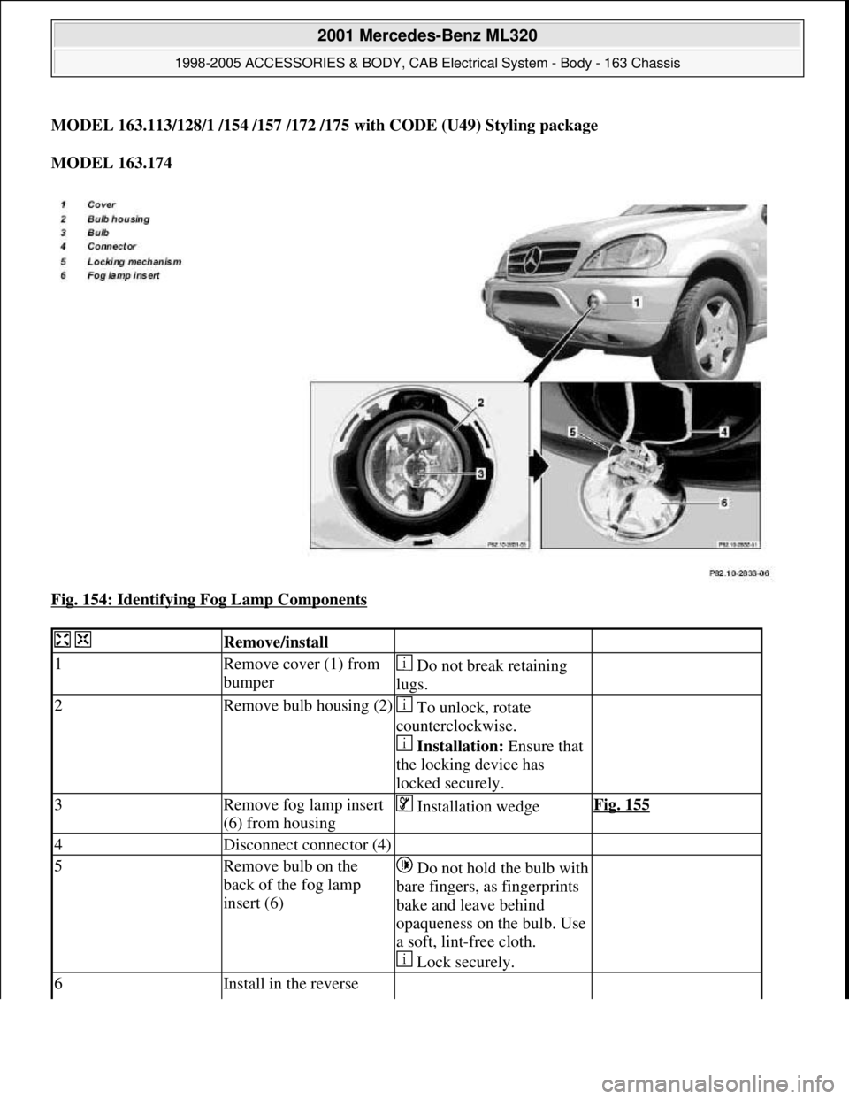
MODEL 163.113/128/1 /154 /157 /172 /175 with CODE (U49) Styling package
MODEL 163.174
Fig. 154: Identifying Fog Lamp Components
Remove/install
1Remove cover (1) from
bumper Do not break retaining
lugs.
2Remove bulb housing (2) To unlock, rotate
counterclockwise.
Installation: Ensure that
the locking device has
locked securely.
3Remove fog lamp insert
(6) from housing Installation wedgeFig. 155
4Disconnect connector (4)
5Remove bulb on the
back of the fog lamp
insert (6)Do not hold the bulb with
bare fingers, as fingerprints
bake and leave behind
opaqueness on the bulb. Use
a soft, lint-free cloth.
Lock securely.
6Install in the reverse
2001 Mercedes-Benz ML320
1998-2005 ACCESSORIES & BODY, CAB Electrical System - Body - 163 Chassis
me
Saturday, October 02, 2010 3:30:08 PMPage 254 © 2006 Mitchell Repair Information Company, LLC.
Page 1750 of 4133
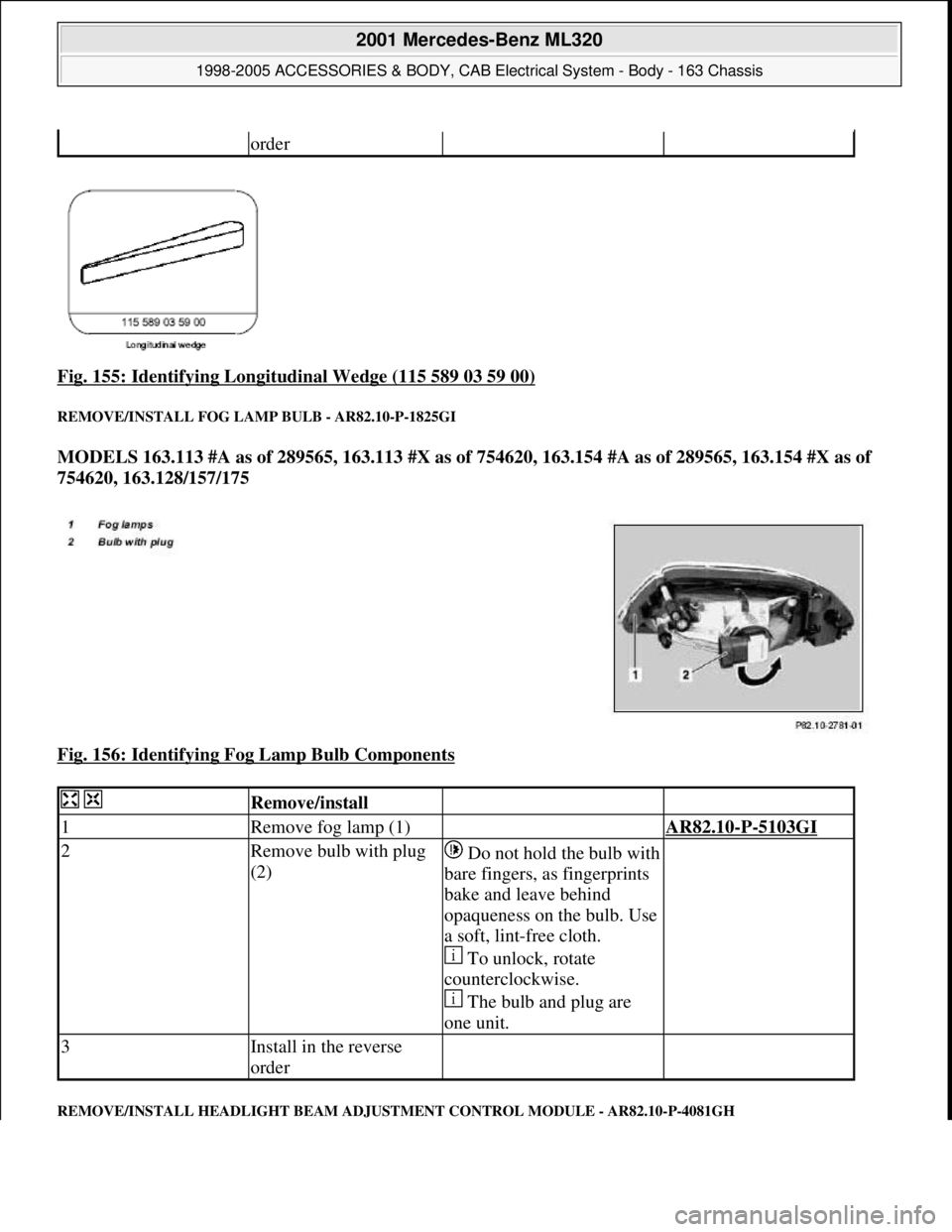
Fig. 155: Identifying Longitudinal Wedge (115 589 03 59 00)
REMOVE/INSTALL FOG LA MP BULB - AR82.10-P-1825GI
MODELS 163.113 #A as of 289565, 163.113 #X as of 754620, 163.154 #A as of 289565, 163.154 #X as of
754620, 163.128/157/175
Fig. 156: Identifying Fog Lamp Bulb Components
REMOVE/INSTALL HEADLIGHT BEAM ADJUSTMENT CONTROL MODULE - AR82.10-P-4081GH
order
Remove/install
1Remove fog lamp (1) AR82.10-P-5103GI
2Remove bulb with plug
(2)Do not hold the bulb with
bare fingers, as fingerprints
bake and leave behind
opaqueness on the bulb. Use
a soft, lint-free cloth.
To unlock, rotate
counterclockwise.
The bulb and plug are
one unit.
3Install in the reverse
order
2001 Mercedes-Benz ML320
1998-2005 ACCESSORIES & BODY, CAB Electr ical System - Body - 163 Chassis
me
Saturday, October 02, 2010 3:30:08 PMPage 255 © 2006 Mitchell Repair Information Company, LLC.
Page 1753 of 4133
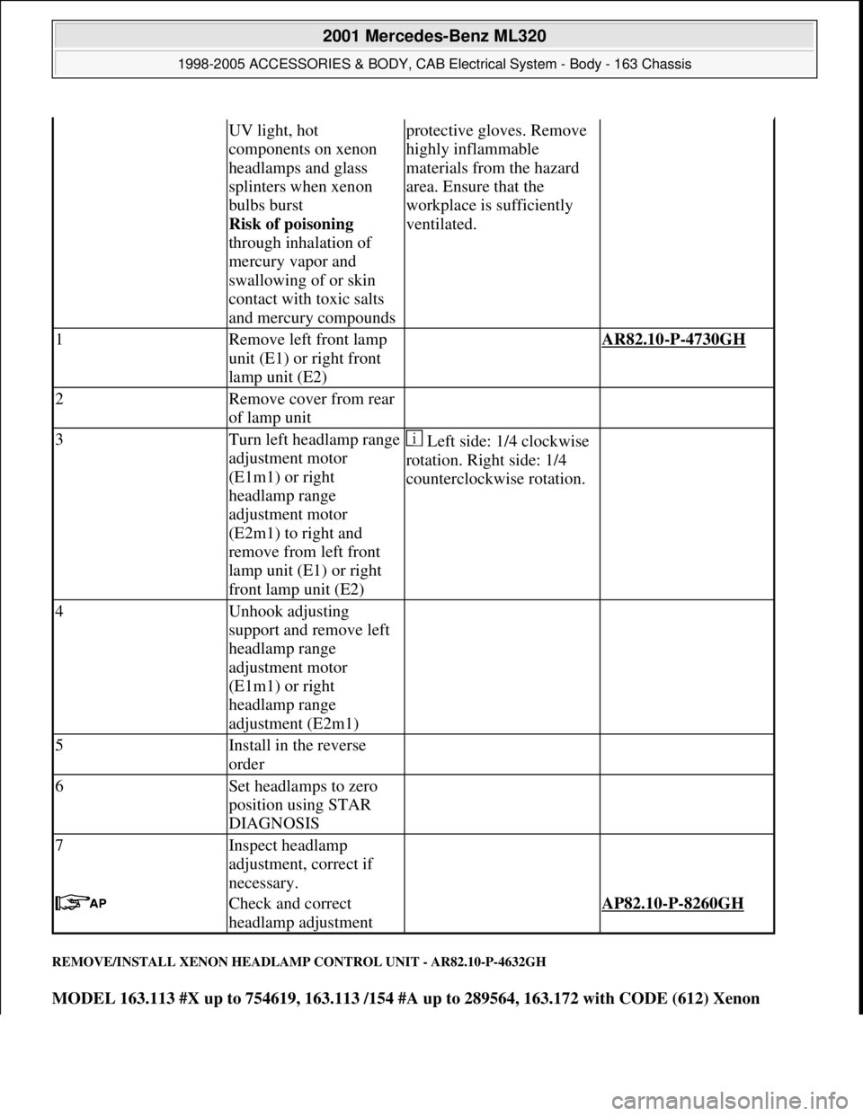
REMOVE/INSTALL XENON HEADLAMP CONTROL UNIT - AR82.10-P-4632GH
MODEL 163.113 #X up to 754619, 163.113 /154 #A up to 289564, 163.172 with CODE (612) Xenon
UV light, hot
components on xenon
headlamps and glass
splinters when xenon
bulbs burst
Risk of poisoning
through inhalation of
mercury vapor and
swallowing of or skin
contact with toxic salts
and mercury compoundsprotective gloves. Remove
highly inflammable
materials from the hazard
area. Ensure that the
workplace is sufficiently
ventilated.
1Remove left front lamp
unit (E1) or right front
lamp unit (E2) AR82.10-P-4730GH
2Remove cover from rear
of lamp unit
3Turn left headlamp range
adjustment motor
(E1m1) or right
headlamp range
adjustment motor
(E2m1) to right and
remove from left front
lamp unit (E1) or right
front lamp unit (E2) Left side: 1/4 clockwise
rotation. Right side: 1/4
counterclockwise rotation.
4Unhook adjusting
support and remove left
headlamp range
adjustment motor
(E1m1) or right
headlamp range
adjustment (E2m1)
5Install in the reverse
order
6Set headlamps to zero
position using STAR
DIAGNOSIS
7Inspect headlamp
adjustment, correct if
necessary.
Check and correct
headlamp adjustment AP82.10-P-8260GH
2001 Mercedes-Benz ML320
1998-2005 ACCESSORIES & BODY, CAB Electrical System - Body - 163 Chassis
me
Saturday, October 02, 2010 3:30:09 PMPage 258 © 2006 Mitchell Repair Information Company, LLC.
Page 1755 of 4133
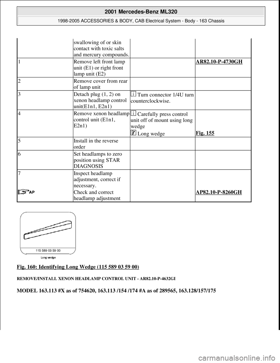
Fig. 160: Identifying Long Wedge (115 589 03 59 00)
REMOVE/INSTALL XENON HEADLAMP CONTROL UNIT - AR82.10-P-4632GI
MODEL 163.113 #X as of 754620, 163.113 /154 /174 #A as of 289565, 163.128/157/175
swallowing of or skin
contact with toxic salts
and mercury compounds.
1Remove left front lamp
unit (E1) or right front
lamp unit (E2) AR82.10-P-4730GH
2Remove cover from rear
of lamp unit
3Detach plug (1, 2) on
xenon headlamp control
unit(E1n1, E2n1)Turn connector 1/4U turn
counterclockwise.
4Remove xenon headlamp
control unit (E1n1,
E2n1) Carefully press control
unit off of mount using long
wedge
Long wedgeFig. 155
5Install in the reverse
order
6Set headlamps to zero
position using STAR
DIAGNOSIS
7Inspect headlamp
adjustment, correct if
necessary.
Check and correct
headlamp adjustment AP82.10-P-8260GH
2001 Mercedes-Benz ML320
1998-2005 ACCESSORIES & BODY, CAB Electrical System - Body - 163 Chassis
me
Saturday, October 02, 2010 3:30:09 PMPage 260 © 2006 Mitchell Repair Information Company, LLC.
Page 1881 of 4133
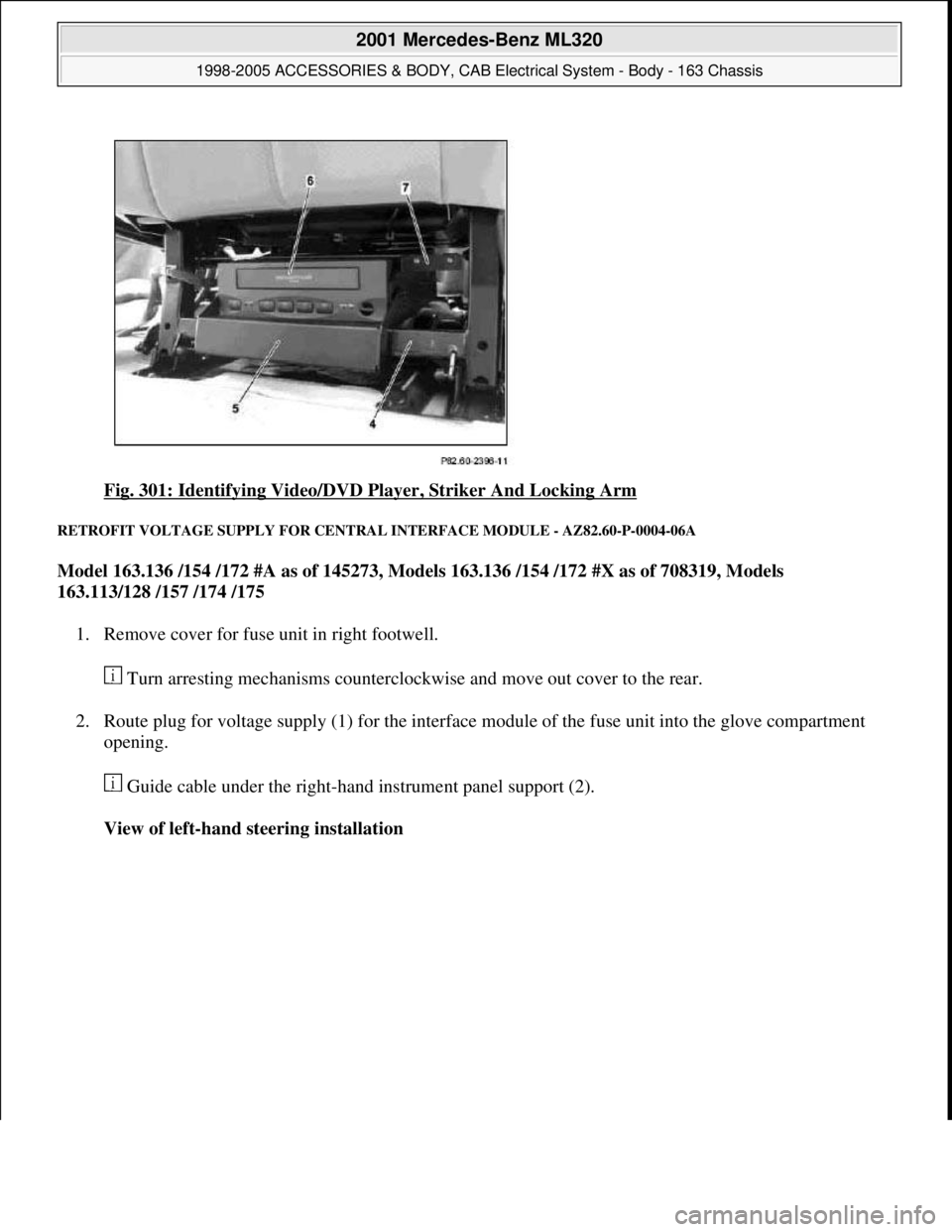
Fig. 301: Identifying Video/DVD Player, Striker And Locking Arm
RETROFIT VOLTAGE SUPPLY FOR CENTRAL INTERFACE MODULE - AZ82.60-P-0004-06A
Model 163.136 /154 /172 #A as of 145273, Models 163.136 /154 /172 #X as of 708319, Models
163.113/128 /157 /174 /175
1. Remove cover for fuse unit in right footwell.
Turn arresting mechanisms counterclockwise and move out cover to the rear.
2. Route plug for voltage supply (1) for the interface module of the fuse unit into the glove compartment
opening.
Guide cable under the right-hand instrument panel support (2).
View of left-hand steering installation
2001 Mercedes-Benz ML320
1998-2005 ACCESSORIES & BODY, CAB Electrical System - Body - 163 Chassis
me
Saturday, October 02, 2010 3:30:12 PMPage 386 © 2006 Mitchell Repair Information Company, LLC.