1997 MERCEDES-BENZ ML320 Mode E
[x] Cancel search: Mode EPage 1 of 4133
AIR BAG RESTRAINT SYSTEM
1998 AIR BAG RESTRAINT SYSTEMS Mercedes-Benz
DESCRIPTION & OPERATION
All models are equipped with Supplemental Restraint System (SRS). The main components of SRS are a driver
air bag module, passenger air bag module, control unit, SRS warning light, driver knee bolster, passenger knee
bolster, and Emergency Tensioning Retractor (ETR) seat belt assembly. Additionally, all vehicles provide
driver-side and passenger-side impact protection by side air bags which are mounted in the driver-side and
passenger-side doors. Each of the door mounted side air bags utilize sensors which recognize lateral
acceleration durin
g side impact and signal this to the control module. See Fig. 1. NOTE: Information on ML320 is not available. For WIRING DIAGRAMS, See Fig. 32
.
WARNING:To avoid injury from accidental air bag deployment, read and carefully
follow all WARNINGS and SERVICE PRECAUTIONS
.
1998 Mercedes-Benz ML320
AIR BAG RESTRAINT SYSTEM 1998 AIR BAG RESTRAINT SYSTEMS Mercedes-Benz
1998 Mercedes-Benz ML320
AIR BAG RESTRAINT SYSTEM 1998 AIR BAG RESTRAINT SYSTEMS Mercedes-Benz
me
Saturday, October 02, 2010 3:33:13 PMPage 1 © 2006 Mitchell Repair Information Company, LLC.
me
Saturday, October 02, 2010 3:33:18 PMPage 1 © 2006 Mitchell Repair Information Company, LLC.
Page 3 of 4133
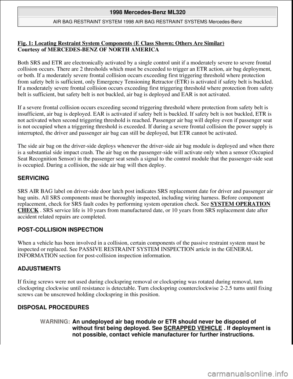
Fig. 1: Locating Restraint System Components (E Class Shown; Others Are Similar)
Courtesy of MERCEDES-BENZ OF NORTH AMERICA
Both SRS and ETR are electronically activated by a single control unit if a moderately severe to severe frontal
collision occurs. There are 2 thresholds which must be exceeded to trigger an ETR action, air bag deployment,
or both. If a moderately severe frontal collision occurs exceeding first triggering threshold where protection
from safety belt is sufficient, only Emergency Tensioning Retractor (ETR) is activated if safety belt is buckled.
If a moderately severe frontal collision occurs exceeding first triggering threshold where protection from safety
belt is sufficient, but safety belt is not buckled, air bag is deployed and EAR is not activated.
If a severe frontal collision occurs exceeding second triggering threshold where protection from safety belt is
insufficient, air bag is deployed. EAR is activated if safety belt is buckled. If safety belt is not buckled, ETR is
not activated when second triggering threshold is reached. Passenger air bag will deploy even if passenger seat
is not occupied when a triggering threshold is exceeded. If during a severe frontal collision the power supply is
interrupted, the driver and passenger air bag can still be deployed, but ETR cannot be activated.
The side air bag on the driver-side deploys whenever the driver-side air bag module is deployed and when there
is a substantial side impact crash. The air bag on the passenger-side will activate only when a sensor (Occupied
Seat Recognition Sensor) in the passenger seat sends a signal to the control module that the passenger-side seat
is occupied. During a collision, the side air bag will then deploy.
SERVICING
SRS AIR BAG label on driver-side door latch post indicates SRS replacement date for driver and passenger air
bag units. All SRS components must be thoroughly inspected, including wiring harness. Before component
replacement, check for SRS fault codes by performing system operation check. See SYSTEM OPERATION
CHECK . SRS service life is 10 years from manufactured date, or 10 years from SRS replacement date after
accident related repairs are completed.
POST-COLLISION INSPECTION
When a vehicle has been involved in a collision, certain components of the passive restraint system must be
inspected or replaced. See PASSIVE RESTRAINT SYSTEM INSPECTION article in the GENERAL
INFORMATION section for post-collision inspection information.
ADJUSTMENTS
If fixing screws were not used during clockspring removal or clockspring was rotated during removal, turn
clockspring clockwise until resistance is detectable. Turn clockspring counterclockwise 2-2.5 turns until fixing
screws can be unscrewed holding clockspring in this position.
DISPOSAL PROCEDURES
WARNING:An undeployed air bag module or ETR should never be disposed of
without first being deployed. See SCRAPPED VEHICLE
. If deployment is
not possible, contact vehicle manufacturer for further instructions.
1998 Mercedes-Benz ML320
AIR BAG RESTRAINT SYSTEM 1998 AIR BAG RESTRAINT SYSTEMS Mercedes-Benz
me
Saturday, October 02, 2010 3:33:13 PMPage 3 © 2006 Mitchell Repair Information Company, LLC.
Page 9 of 4133
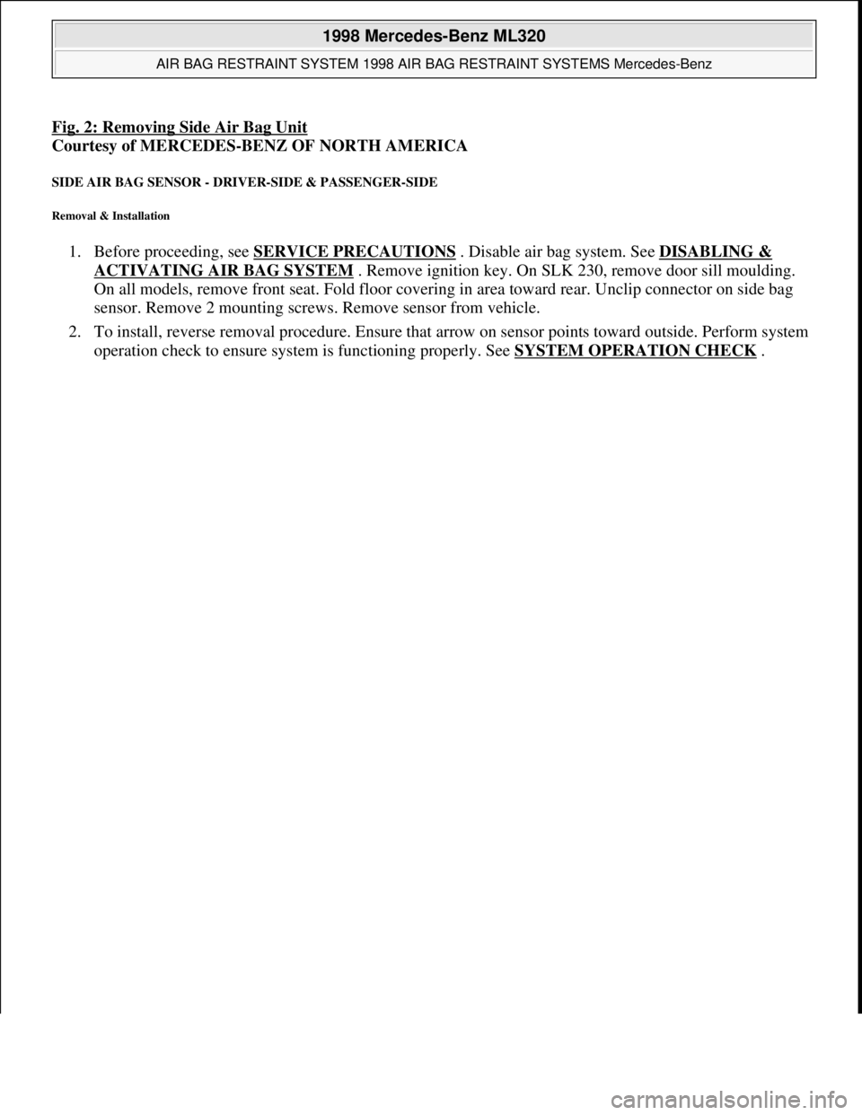
Fig. 2: Removing Side Air Bag Unit
Courtesy of MERCEDES-BENZ OF NORTH AMERICA
SIDE AIR BAG SENSOR - DRIVER-SIDE & PASSENGER-SIDE
Removal & Installation
1. Before proceeding, see SERVICE PRECAUTIONS . Disable air bag system. See DISABLING &
ACTIVATING AIR BAG SYSTEM . Remove ignition key. On SLK 230, remove door sill moulding.
On all models, remove front seat. Fold floor covering in area toward rear. Unclip connector on side bag
sensor. Remove 2 mounting screws. Remove sensor from vehicle.
2. To install, reverse removal procedure. Ensure that arrow on sensor points toward outside. Perform system
operation check to ensure system is functioning properly. See SYSTEM OPERATION CHECK
.
1998 Mercedes-Benz ML320
AIR BAG RESTRAINT SYSTEM 1998 AIR BAG RESTRAINT SYSTEMS Mercedes-Benz
me
Saturday, October 02, 2010 3:33:14 PMPage 9 © 2006 Mitchell Repair Information Company, LLC.
Page 20 of 4133
with HHT connected to DLC and ignition key removed. Remove driver-side air bag module. Disconnect
driver-side air bag module squib connector R12/3. Connect Resistance Substitution Unit (124 589 09 63)
to driver-side air bag module squib connector (harness side). Set resistance substitution unit to 2 ohms.
Turn ignition key to position "2". Read NOMINAL VALUE/HHT DISPLAY column. If HHT displays a
check, replace driver-side air bag module. If HHT displays an "F", go to step 3.2.
Read TEST CONNECTION (NOT FOR HHT) column. Horn/air bag clockspring connector A45x1,
terminals No. 1 and 2 are identified. Read TEST CONDITION column. Test circuit with HHT connected
to DLC. Remove ignition key. Connect Resistance Substitution Unit (124 589 09 63 00) to horn/air bag
clockspring connector A45x1. Set resistance substitution unit to 2 ohms. Read NOMINAL VALUE/HHT
DISPLAY column. If HHT displays a check, check horn/air bag clockspring for continuity. Replace
horn/air bag clockspring as necessary. If HHT displays an "F", go to step 3.4.
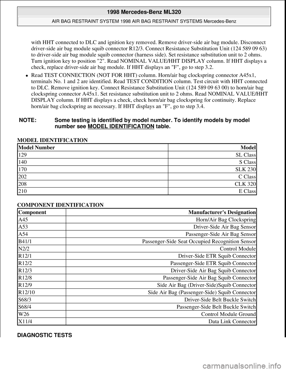
MODEL IDENTIFICATION
COMPONENT IDENTIFICATION
DIAGNOSTIC TESTS NOTE: Some testing is identified by model number. To identify models by model
number see MODEL IDENTIFICATION
table.
Model NumberModel
129SL Class
140S Class
170SLK 230
202C Class
208CLK 320
210E Class
ComponentManufacturer's Designation
A45Horn/Air Bag Clockspring
A53Driver-Side Air Bag Sensor
A54Passenger-Side Air Bag Sensor
B41/1Passenger-Side Seat Occupied Recognition Sensor
N2/2Control Module
R12/1Driver-Side ETR Squib Connector
R12/2Passenger-Side ETR Squib Connector
R12/3Driver-Side Air Bag Squib Connector
R12/8Passenger-Side Air Bag Squib Connector
R12/9Side Air Bag (Driver-Side)Squib Connector
R12/10Side Air Bag (Passenger-Side) Squib Connector
S68/3Driver-Side Belt Buckle Switch
S68/4Passenger-Side Belt Buckle Switch
W26Control Module Ground
X11/4Data Link Connector
1998 Mercedes-Benz ML320
AIR BAG RESTRAINT SYSTEM 1998 AIR BAG RESTRAINT SYSTEMS Mercedes-Benz
me
Saturday, October 02, 2010 3:33:14 PMPage 20 © 2006 Mitchell Repair Information Company, LLC.
Page 53 of 4133

3 ContentsSnow chains ................................ 179
Winter driving instructions ...... 180
Deep water .................................. 181
Passenger compartment ........... 182
Traveling abroad ........................ 182
Off-Road driving ............................. 183
Trailer towing ................................. 190
Cruise control ................................. 196
Brake assist system (BAS) ............ 199
Antilock brake system (ABS) ....... 201
Four-wheel electronic
traction system (4-ETS+) ..........203
Electronic brake
proportioning (EBP) ..................204
Electronic stability program
(ESP) ...........................................205
Transmission control –
LOW RANGE mode ...................209
What you should know
at the gas station ....................... 212
Check regularly and
before a long trip ....................... 215
Instrument cluster displayMalfunction and indicator
lamps in the
instrument cluster .....................218
On-board diagnostic system –
Check engine malfunction
indicator lamp .............................218
Brake warning lamp ...................219
Supplemental restraint system
(SRS) indicator lamp .................. 219
Fuel reserve warning ................ 220
Electronic stability
program (ESP) / Electronic
traction system (ETS) –
warning lamp ............................. 221
BAS/ESP malfunction
indicator lamp ............................ 221
4-ETS malfunction
indicator lamp ............................ 221
LOW RANGE
indicator lamp ............................ 221
ABS malfunction
indicator lamp ............................ 222Adjustable steering wheel –
indicator lamp .............................222
AIRBAG OFF
indicator lamp .............................222
Seat belt warning lamp .............223
Charge indicator lamp ...............223
Low engine oil level
warning lamp ..............................224
Low engine coolant
level warning ..............................224
Brake pad wear
indicator lamp .............................225
FSS indicator ...............................225
Page 57 of 4133
7 IntroductionProduct information
Kindly observe the following in your own best interest:
We recommend using Mercedes-Benz original parts as well as conversion parts and accessories
explicitly approved by us for your vehicle model.
We have tested these parts to determine their reliability, safety and their special
suitability for Mercedes-Benz vehicles.
We are unable to make an assessment for other products and therefore cannot be held responsible
for them, even if in individual cases an official approval or authorization by governmental or other
agencies should exist. Use of such parts and accessories could adversely affect the safety,
performance or reliability of your vehicle. Please do not use them.
Mercedes-Benz original parts as well as conversion parts and accessories approved by us are available
at your authorized Mercedes-Benz Light Truck Center where you will receive comprehensive information, also on
permissible technical modifications, and where proper installation will be performed.
Page 69 of 4133
19 Instruments and controls
Te ch n ica l
data Instruments
and controlsOperation DrivingInstrument
cluster displayPractical hints Car care Index For more detailed descriptions see index on page 300.
For adjustment of air outlets, refer to climate control,
see page 98.
1Cup holder, see page 114
2Parking brake release, see page 173
3Parking brake pedal, see page 173
4Steering wheel adjustment lever, see page 70
5Headlamp washer switch, see page 94
6Exterior lamp switch, see page 90
7Cruise control switch, see page 196
8Instrument cluster, see page 76
9Hazard warning flasher switch, see page 94
10Horn (with key in steering lock position 1 or 2),
Driver airbag, see page 56
11Steering lock with ignition / starter switch, see
page 162
12Switch for exterior rear view mirrors, electrically
folding, see page 75
13Windshield wiper / washer switch, see page 9514Transmission control – LOW RANGE mode, see
page 209
15Indicator lamp for antitheft alarm system
16Auxiliary front fog lamp / rear fog lamp switch, see
page 92
17MCS (Optional Modular Control System), see
separate operator’s manual
18Front passenger airbag, see page 56
19Glove box (illuminated with key in steering lock
position 1 or 2)
20Cup holder, see page 114
21Storage compartment
22Air recirculation switch, see page 98
23Air conditioner on /off switch, see page 98
24Air volume control switch
25Temperature selector switch
26Air distribution switch
27Electrical outlet, see page 230
Page 86 of 4133
36 Tow-away protection
Te ch n ica l
data Instruments
and controlsOperationDrivingInstrument
cluster displayPractical hints Car care Index
Tow-away alarm and glass breakage sensor
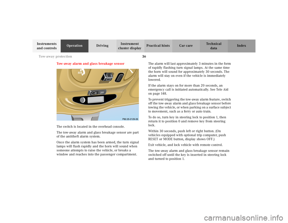
The switch is located in the overhead console.
The tow-away alarm and glass breakage sensor are part
of the antitheft alarm system.
Once the alarm system has been armed, the turn signal
lamps will flash rapidly and the horn will sound when
someone attempts to raise the vehicle, or breaks a
window and reaches into the passenger compartment.The alarm will last approximately 3 minutes in the form
of rapidly flashing turn signal lamps. At the same time
the horn will sound for approximately 30 seconds. The
alarm will stay on even if the vehicle is immediately
lowered.
If the alarm stays on for more than 20 seconds, an
emergency call is initiated automatically. See Tele Aid
on page 148.
To prevent triggering the tow-away alarm feature, switch
off the tow-away alarm and glass breakage sensor before
towing the vehicle, or when parking on a surface subject
to movement, such as a ferry or auto train.
To do so, turn key in steering lock to position 1, then
return it to position 0 and remove key from steering
lock.
Within 30 seconds, push left or right button. (On
vehicles equipped with optional trip computer, push
RESET or MODE button, display shows OFF.)
Exit vehicle, and lock vehicle with remote control.
The tow-away alarm and glass breakage sensor remain
switched off until the key is inserted in steering lock
and turned to position 1.