1997 MERCEDES-BENZ ML320 clock
[x] Cancel search: clockPage 1987 of 4133
AR82.10-P-1825GH
Remove/install fog lamp bulb
23.4.01
MODEL
163.113 /128 /136 /154 /157 /172 /175 with CODE (U49) Styling package
MODEL
163.174
P82.10-2833-06
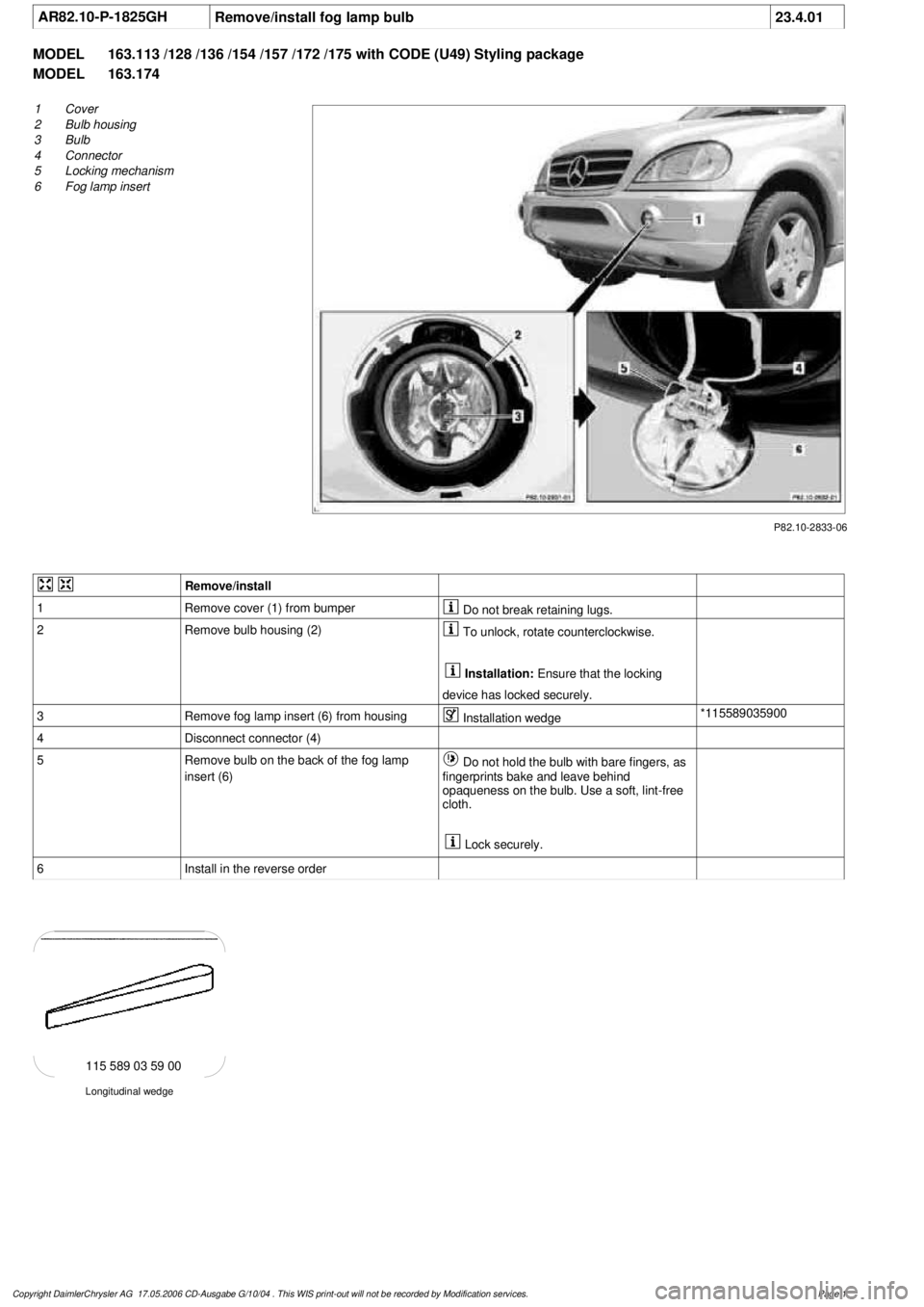
1
Cover
2
Bulb housing
3
Bulb
4
Connector
5
Locking mechanism
6
Fog lamp insert
Remove/install
1
Remove cover (1) from bumper
Do not break retaining lugs.
2
Remove bulb housing (2)
To unlock, rotate counterclockwise.
Installation:
Ensure that the locking
device has locked securely.
3
Remove fog lamp insert (6) from housing
Installation wedge
*115589035900
4
Disconnect connector (4)
5
Remove bulb on the back of the fog lamp
insert (6)
Do not hold the bulb with bare fingers, as
fingerprints bake and leave behind
opaqueness on the bulb. Use a soft, lint-free
cloth.
Lock securely.
6
Install in the reverse order
Longitudinal wedge
115 589 03 59 00
Copyright DaimlerChrysler AG 17.05.2006 CD-Ausgabe G/10/04 . This WIS print-out will not be recorde
d by Modification services.
Page 1
Page 2042 of 4133
3. Normalize side power windows. See NORMALIZING POWER WINDOWS .
4. Start engine and run at idle. Turn steering wheel from one lock position to the other to activate steering
angle sensor. Center steering wheel. Message "EI. STAB. PROGRAM GO TO GARAGE" should erase
from multifunction display panel.
5. If equipped, normalize tilting/sliding roof. See NORMALIZING TILTING/SLIDING ROOF
.
6. If equipped, normalize memory power seats, steering column and outside mirror if components are
installed. See NORMALIZING MEMORY POWER SEATS, STEERING COLUMN & OUTSIDE
MIRROR .
Normalizing Power Windows
1. Completely close each window with manual switch. Hold switch in closed position for .3 second.
2. Repeat procedure for each power window.
Normalizing Memory Power Seats, Steering Column & Outside Mirror
1. Using manual switch, move seat to each end position and hold for .3 second. Repeat procedure for each
switch except rear stop of backrest.
2. Repeat procedure for end positions of steering wheel and outside mirrors.
Normalizing Tilting/Sliding Roof
Open roof with SR switch until mechanical stop is reached. Continue to press switch for .5 seconds.
Setting Time
1. Use bottom left button on steering wheel to scroll through menus on instrument cluster to "Settings"
menu.
2. Move selection marker with + or - button to "Time" submenu.
3. Press up or down arrows to "Clock, hours" setting. Confirm selection marker is on the hour setting.
4. Press + or - to set hour. Press reset knob in instrument cluster to confirm.
5. Move selection marker with + or - button to "Time" submenu.
6. Press up or down arrows to "Clock, minutes" setting. Confirm selection marker is on the minutes setting.
7. Press + or - to set minute. Press reset knob in instrument cluster to confirm.
TESTING
If generator malfunctions, check for Diagnostic Trouble Codes (DTCs) in Motor Electronics Sequential Fuel
Injection (ME-SFI) system. See appropriate SELF-DIAGNOSTICS article in ENGINE PERFORMANCE. If
cause of generator malfunction is not engine performance related, replace generator.
RETRIEVING & ERASING DIAGNOSTIC TROUBLE CODES
NOTE: Before replacing any component that scan tool suggests are faulty, ensure that
all wiring connections and harness connectors are okay. Ensure that power and
2001 Mercedes-Benz ML320
2001-04 STARTING & CHARGING SYSTEMS Generators & Regulators - 163 Chassis
me
Saturday, October 02, 2010 3:20:32 PMPage 8 © 2006 Mitchell Repair Information Company, LLC.
Page 2066 of 4133

GF54.30-P-2004A
Control buttons, location/task
24.10.96
MODEL
129, 140 as of 1.6.96,
163, 170
The instrument cluster has two control buttons which are on the left
or right next to the speedometer.
The
right control button
is used to adjust the time (refer to Owner's
Manual).
-----------------------------------------------------------------------------------------
The
left control button
is used
D
to regulate the instrument illumination
D
to activate the display illumination
D
to reset the trip odometer display
D
to operate the maintenance display (model 170 only bis 05.97)
D
to operate the Active Service System ASSYST (as of 06.97)
-----------------------------------------------------------------------------------------
n
Purpose/function of terminal 58d, instrument
display illumination
Engines 112, 113, 611 (engines with oil
sensor)
GF54.30-P-3008A
n
Electronic clock
GF54.30-P-3011A
n
Active Service System (ASSYST)
GF00.20-P-0003-01A
Operating instructions, resetting
Model 210 as of 01.03.97 with engines M111,
OM 602, OM 604, OM 605 and
OM 606
As of 06/97 models 129, 140, 170, 202 except
engines 112, 113, 611
(valid for engines with oil level switch)
GF00.20-P-0003-01B
Copyright DaimlerChrysler AG 05.06.2006 CD-Ausgabe G/10/04 . This WIS print-out will not be recorde
d by Modification services.
Page 1
Page 2068 of 4133
AR20.00-P-1142M
Drain, pour in coolant
8.11.99
ENGINE
612.963 in MODEL 163.113
P20.20-2083-12
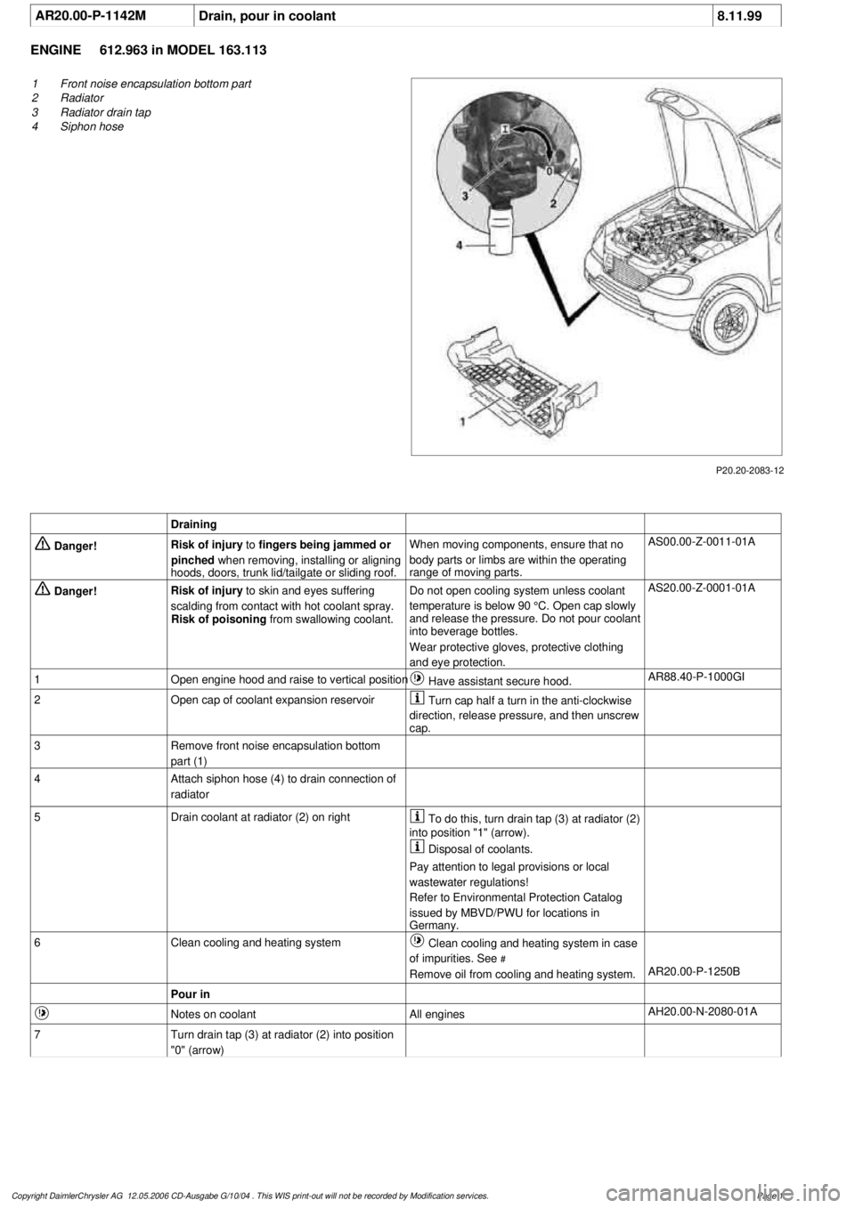
1
Front noise encapsulation bottom part
2
Radiator
3
Radiator drain tap
4
Siphon hose
Draining
Danger!
Risk of injury
to
fingers being jammed or
pinched
when removing, installing or aligning
hoods, doors, trunk lid/tailgate or sliding roof.
When moving components, ensure that no
body parts or limbs are within the operating
range of moving parts.
AS00.00-Z-0011-01A
Danger!
Risk of injury
to skin and eyes suffering
scalding from contact with hot coolant spray.
Risk of poisoning
from swallowing coolant.
Do not open cooling system unless coolant
temperature is below 90 °C. Open cap slowly
and release the pressure. Do not pour coolant
into beverage bottles.
Wear protective gloves, protective clothing
and eye protection.
AS20.00-Z-0001-01A
1
Open engine hood and raise to vertical position
Have assistant secure hood.
AR88.40-P-1000GI
2
Open cap of coolant expansion reservoir
Turn cap half a turn in the anti-clockwise
direction, release pressure, and then unscrew
cap.
3
Remove front noise encapsulation bottom
part (1)
4
Attach siphon hose (4) to drain connection of
radiator
5
Drain coolant at radiator (2) on right
To do this, turn drain tap (3) at radiator (2)
into position "1" (arrow).
Disposal of coolants.
Pay attention to legal provisions or local
wastewater regulations!
Refer to Environmental Protection Catalog
issued by MBVD/PWU for locations in
Germany.
6
Clean cooling and heating system
Clean cooling and heating system in case
of impurities. See
#
Remove oil from cooling and heating system.
AR20.00-P-1250B
Pour in
Notes on coolant
All engines
AH20.00-N-2080-01A
7
Turn drain tap (3) at radiator (2) into position
"0" (arrow)
Copyright DaimlerChrysler AG 12.05.2006 CD-Ausgabe G/10/04 . This WIS print-out will not be recorde
d by Modification services.
Page 1
Page 2071 of 4133

1
Open cooling system cap (2) on coolant
expansion reservoir (1)
Cap with detent:
Turn cap carefully as far as the first detent,
release pressure, and then unscrew cap.
2-stage and 1-stage cap: Rotate cap half
a revolution in a counterclockwise direction,
release overpressure, then unscrew cap.
2.1Remove engine compartment paneling
Models 129, 202, 208, 210
AR61.20-P-1105AB
Models 163.172/ 174/ 175
AR61.20-P-1105GH
Models 163.113/ 128
AR94.30-P-5400GH
Model 211
AR61.20-P-1105T
Models 215, 220
AR61.20-P-1105M
Model 230
AR61.20-P-1105R
2.2Remove underride guard
Only on model 463
3.1
Remove air guide
Only on model 163 with engine 113.942
4
Drain coolant
Model 163: For draining coolant, detach
bottom coolant line at radiator or at coolant
pump.
Collect coolant Observe regulations for
disposal of coolant.
Installation:
On model 163 replace
radiator connection of hose clamps to coolant
hose, otherwise this can cause a damage to
the bolt/thread.
Hose clamp
*BA20.20-P-1004-01A
Pouring in
5
Pour in coolant
All except engine 137
*BF20.00-P-1001-02K
Engine 137
*BF20.00-P-1001-02M
Notes on coolant level
Engines 112, 113, 137, 275, 285
AH20.00-P-1142-01V
Notes on coolant level
Model 163 with engines 111, 112, 113
AH20.00-P-1142-01GH
6
Bleed cooling system
Let engine run, put heater on full heat
output.
Except stationary heater, code 228
AR20.00-P-1142-06GA
With stationary heater code 228
7
Inspect cooling system for leaks
AR20.00-P-1010HA
Radiator, coolant hoses
Number
Designation
Engines
112.942/
970,
113.942/
965/981
BA20.20-P-1004-01A
Hose clamp
Nm
3
Designation
Engines
112.910 /920
in model 202,
112.940
in model 208
Engines
112.911/921/941
in model 210
Engines
112.922/944/972
in model 220
BF20.00-P-1001-02K
Cooling system
Total capacity
Liters
Y
9.5
Y
10.0
Y
10.5
Capacity of
anticorrosion/antifreeze agent
down to -37°C
Liters
Y
4.75
Y
5.0
Y
5.0
Capacity of anticorrosion/
antifreeze agent down
to -45°C
Liters
Y
5.25
Y
5.5
Y
5.5
Specifications for Operating
Fluids
SheetBB00.40-P-0310-01ABB00.40-P-0310-01ABB00.40-P-0310-01A
SheetBB00.40-P-0325-00ABB00.40-P-0325-00ABB00.40-P-0325-00A
Copyright DaimlerChrysler AG 12.05.2006 CD-Ausgabe G/10/04 . This WIS print-out will not be recorde
d by Modification services.
Page 2
Page 2075 of 4133
AR20.00-P-1142M
Drain, pour in coolant
8.11.99
ENGINE
612.963 in MODEL 163.113
P20.20-2083-12
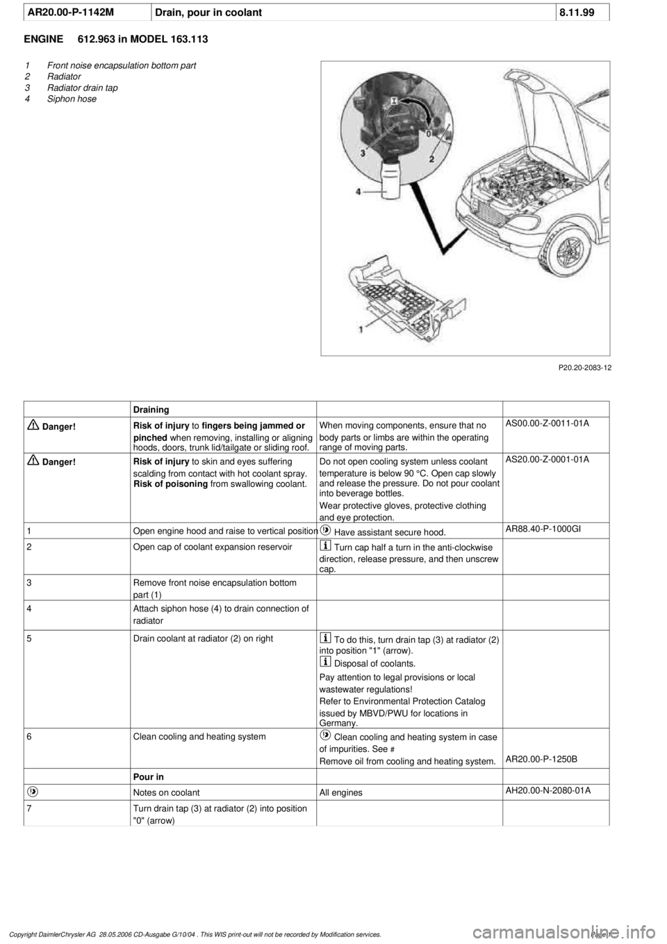
1
Front noise encapsulation bottom part
2
Radiator
3
Radiator drain tap
4
Siphon hose
Draining
Danger!
Risk of injury
to
fingers being jammed or
pinched
when removing, installing or aligning
hoods, doors, trunk lid/tailgate or sliding roof.
When moving components, ensure that no
body parts or limbs are within the operating
range of moving parts.
AS00.00-Z-0011-01A
Danger!
Risk of injury
to skin and eyes suffering
scalding from contact with hot coolant spray.
Risk of poisoning
from swallowing coolant.
Do not open cooling system unless coolant
temperature is below 90 °C. Open cap slowly
and release the pressure. Do not pour coolant
into beverage bottles.
Wear protective gloves, protective clothing
and eye protection.
AS20.00-Z-0001-01A
1
Open engine hood and raise to vertical position
Have assistant secure hood.
AR88.40-P-1000GI
2
Open cap of coolant expansion reservoir
Turn cap half a turn in the anti-clockwise
direction, release pressure, and then unscrew
cap.
3
Remove front noise encapsulation bottom
part (1)
4
Attach siphon hose (4) to drain connection of
radiator
5
Drain coolant at radiator (2) on right
To do this, turn drain tap (3) at radiator (2)
into position "1" (arrow).
Disposal of coolants.
Pay attention to legal provisions or local
wastewater regulations!
Refer to Environmental Protection Catalog
issued by MBVD/PWU for locations in
Germany.
6
Clean cooling and heating system
Clean cooling and heating system in case
of impurities. See
#
Remove oil from cooling and heating system.
AR20.00-P-1250B
Pour in
Notes on coolant
All engines
AH20.00-N-2080-01A
7
Turn drain tap (3) at radiator (2) into position
"0" (arrow)
Copyright DaimlerChrysler AG 28.05.2006 CD-Ausgabe G/10/04 . This WIS print-out will not be recorde
d by Modification services.
Page 1
Page 2078 of 4133
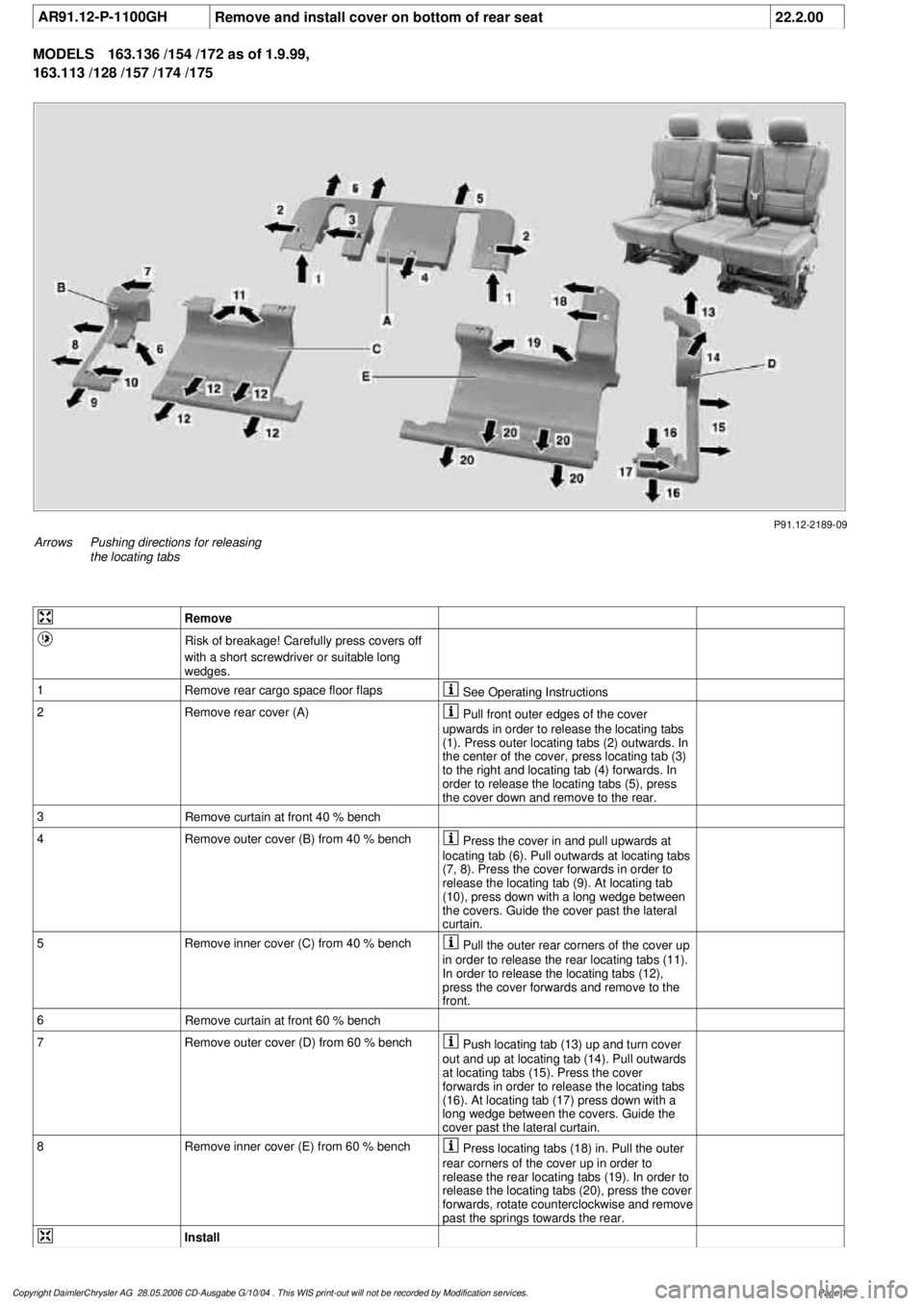
AR91.12-P-1100GH
Remove and install cover on bottom of rear seat
22.2.00
MODELS
163.136 /154 /172 as of 1.9.99,
163.113 /128 /157 /174 /175
P91.12-2189-09
Arrows
Pushing directions for releasing
the locating tabs
Remove
Risk of breakage! Carefully press covers off
with a short screwdriver or suitable long
wedges.
1
Remove rear cargo space floor flaps
See Operating Instructions
2Remove rear cover (A)
Pull front outer edges of the cover
upwards in order to release the locating tabs
(1). Press outer locating tabs (2) outwards. In
the center of the cover, press locating tab (3)
to the right and locating tab (4) forwards. In
order to release the locating tabs (5), press
the cover down and remove to the rear.
3
Remove curtain at front 40 % bench
4
Remove outer cover (B) from 40 % bench
Press the cover in and pull upwards at
locating tab (6). Pull outwards at locating tabs
(7, 8). Press the cover forwards in order to
release the locating tab (9). At locating tab
(10), press down with a long wedge between
the covers. Guide the cover past the lateral
curtain.
5
Remove inner cover (C) from 40 % bench
Pull the outer rear corners of the cover up
in order to release the rear locating tabs (11).
In order to release the locating tabs (12),
press the cover forwards and remove to the
front.
6
Remove curtain at front 60 % bench
7
Remove outer cover (D) from 60 % bench
Push locating tab (13) up and turn cover
out and up at locating tab (14). Pull outwards
at locating tabs (15). Press the cover
forwards in order to release the locating tabs
(16). At locating tab (17) press down with a
long wedge between the covers. Guide the
cover past the lateral curtain.
8
Remove inner cover (E) from 60 % bench
Press locating tabs (18) in. Pull the outer
rear corners of the cover up in order to
release the rear locating tabs (19). In order to
release the locating tabs (20), press the cover
forwards, rotate counterclockwise and remove
past the springs towards the rear.
Install
Copyright DaimlerChrysler AG 28.05.2006 CD-Ausgabe G/10/04 . This WIS print-out will not be recorde
d by Modification services.
Page 1
Page 2079 of 4133

9
Install inner cover (E) at 60 % bench
Insert cover past the springs from the rear
and rotate into position in a clockwise
direction. Insert locating tabs (19). Press the
front cover down and reset so that locating
tabs (20) engage. Press rear cover down until
locating tabs (18) engage.
10
Install outer cover (D) at 60 % bench
Guide the cover past the lateral curtain.
Insert locating tab (17), push front cover down
and reset so that locating tabs (16) engage.
Press the outer edge of the cover down and
insert lateral locating tabs (15). Raise rear
cover on the inside, press down until locating
tab (14) and rear locating tab (13) engage.
11
Install curtain at front 60 % bench
12
Install inner cover (C) at 40 % bench
Insert cover from the front and insert
locating tabs (11). Press the front cover down
and reset so that locating tabs (12) engage.
13
Install outer cover (B) at 40 % bench
Guide the cover past the lateral curtain.
Insert locating tab (10), push front cover down
and reset so that locating tab (9) engages.
Press the outer edge of the cover down and
insert lateral locating tabs (8). Insert locating
tab (7), push cover down at locating tab (6)
and engage.
14
Install curtain at front 40 % bench
15
Install rear cover (A)
Insert cover from the rear and press down
and forwards so that locating tabs (5) engage.
Press front ends of the cover down, so that
locating tabs (2, 3, 4) engage. Insert locating
tabs (1) into covers (C, E).
Copyright DaimlerChrysler AG 28.05.2006 CD-Ausgabe G/10/04 . This WIS print-out will not be recorde
d by Modification services.
Page 2