1997 MERCEDES-BENZ ML320 clock
[x] Cancel search: clockPage 1125 of 4133

321 Index
Chart
Fuses 287
CHECK ENGINE malfunction indicator
lamp 248
Checking
Coolant level 215, 222
Oil level 218
Tire inflate pressure 216
Vehicle lighting 216
Checking weights
Trailer and vehicle 208
Checklist
Off-road driving 201
Returning from off-road driving 206
Child safety 67
Airbags 60
Infant and child restraint systems 64,
68
LATCH child seat mounts 72
Child safety switch see Blocking of rear
door window operation 73Cigarette lighter
Front center console 168
Cleaning
Cup holder 238
Gear selector lever 238
Hard plastic trim items 238
Headlamps 131
Headliner 238
Instrument cluster 238
Leather upholstery 239
Light alloy wheels 238
MB Tex upholstery 239
Plastic and rubber parts 239
Seat belts 238
Steering wheel 238
Windows 237
Windshield 50
Wiper blades 237
Clock 26, 118Closing
Glove box 164
Hood 218
Liftgate 92
Rear quarter windows* 147
Side windows 145
Sliding/pop-up roof* 148, 265
Closing sliding/pop-up roof*
In an emergency 265
Cockpit 22, 311
Combination switch
High beam flasher 49, 110
Turn signals 49
Windshield wipers 49
Compass 187
Calibrating 188
Setting compass zone 188
Compass zone 188
Consumer information 308
Control and operation of radio
transmitters 211
Page 1139 of 4133

335 Index
Seat belts 64
Cleaning 238
Fastening 42
Height adjustment 45
Proper use of 44, 66
Safety guidelines 62
Warning lamp 253
Seat heater*
Switching off 98
Switching on 98
Seats 95
Adjusting 34
Heater* 98
Manual 35
Power 37
Rapid seat heating* 98
Rear 99
Split rear bench seat 99
Securing cargo
Cargo tie-down rings 158
Selector lever 26
Lock 46
Position 26, 119Self-test
BabySmart
TM airbag deactivation
system 70
Tele Aid* 172
Service
Calling up the service indicator 233
Major service (Service B) 232
Minor service (Service A) 232
Overdue 233
Spare parts
Types 233
When due 232
Service and Warranty Booklet
Loss of 291
Service and warranty information 10
Service indicator 232
Calling up 233
Clearing 232, 233
Service indicator (FSS)
Display messages 256
Service life (tires) 227Service System see FSS
Setting
Cruise control 151
Higher speed in cruise control 152
Hours (clock) 118
Lower speed in cruise control 152
Minutes (clock) 118
Slower speed in cruise control 152
Speed in cruise control 152
Setting date
Trip computer* 186
Setting language
Trip computer* 190
Shift lock 314
Shifting
Gear selector lever positions 122
Into optimal gear range (automatic
transmission) 120
Side impact airbags 64
Side marker lamps
Replacing bulbs 266, 267, 269
Page 1177 of 4133
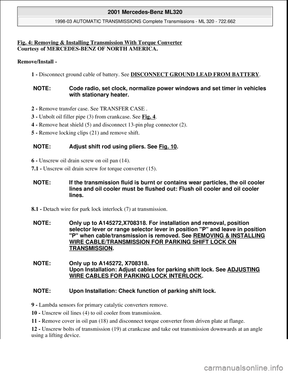
Fig. 4: Removing & Installing Transmission With Torque Converter
Courtesy of MERCEDES-BENZ OF NORTH AMERICA.
Remove/Install -
1 - Disconnect ground cable of battery. See DISCONNECT GROUND LEAD FROM BATTERY
.
2 - Remove transfer case. See TRANSFER CASE .
3 - Unbolt oil filler pipe (3) from crankcase. See Fig. 4
.
4 - Remove heat shield (5) and disconnect 13-pin plug connector (2).
5 - Remove locking clips (21) and remove shift.
6 - Unscrew oil drain screw on oil pan (14).
7.1 - Unscrew oil drain screw for torque converter (15).
8.1 - Detach wire for park lock interlock (7) at transmission.
9 - Lambda sensors for primary catalytic converters remove.
10 - Unscrew oil lines (4) to oil cooler from transmission.
11 - Remove cover in oil pan (18) and disconnect torque converter from driven plate at flange.
12 - Unscrew bolts of transmission (19) at crankcase and take out transmission downwards at an angle
using a lifting device. NOTE: Code radio, set clock, normalize power windows and set timer in vehicles
with stationary heater.
NOTE: Adjust shift rod using pliers. See Fig. 10
.
NOTE: If the transmission fluid is burnt or contains wear particles, the oil cooler
lines and oil cooler must be flushed out: Flush oil cooler and oil cooler
lines.
NOTE: Only up to A145272,X708318. For installation and removal, position
selector lever or range selector lever in position "P" and leave in position
"P" when cable/transmission is removed. See REMOVING & INSTALLING
WIRE CABLE/TRANSMISSION FOR PARKING SHIFT LOCK ON
TRANSMISSION.
NOTE: Only up to A145272, X708318.
Upon Installation: Adjust cables for parking shift lock. See ADJUSTING
WIRE CABLES FOR PARKING LOCK INTERLOCK.
NOTE: Upon Installation: Check function of parking shift lock.
2001 Mercedes-Benz ML320
1998-03 AUTOMATIC TRANSMISSIONS Complete Transmissions - ML 320 - 722.662
me
Saturday, October 02, 2010 3:15:25 PMPage 8 © 2006 Mitchell Repair Information Company, LLC.
Page 1187 of 4133
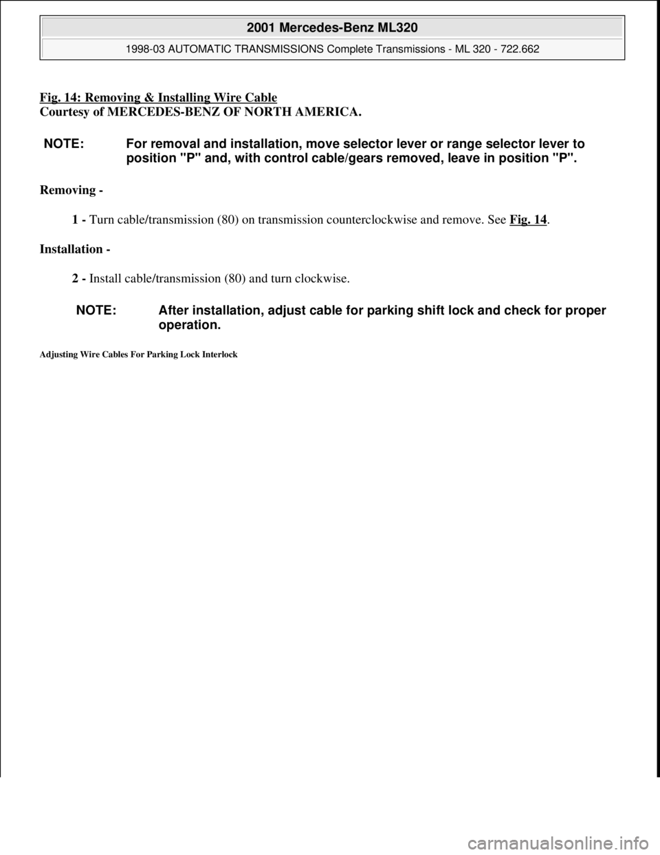
Fig. 14: Removing & Installing Wire Cable
Courtesy of MERCEDES-BENZ OF NORTH AMERICA.
Removing -
1 - Turn cable/transmission (80) on transmission counterclockwise and remove. See Fig. 14
.
Installation -
2 - Install cable/transmission (80) and turn clockwise.
Adjusting Wire Cables For Parking Lock Interlock
NOTE: For removal and installation, move selector lever or range selector lever to
position "P" and, with control cable/gears removed, leave in position "P".
NOTE: After installation, adjust cable for parking shift lock and check for proper
operation.
2001 Mercedes-Benz ML320
1998-03 AUTOMATIC TRANSMISSIONS Complete Transmissions - ML 320 - 722.662
me
Saturday, October 02, 2010 3:15:25 PMPage 18 © 2006 Mitchell Repair Information Company, LLC.
Page 1491 of 4133
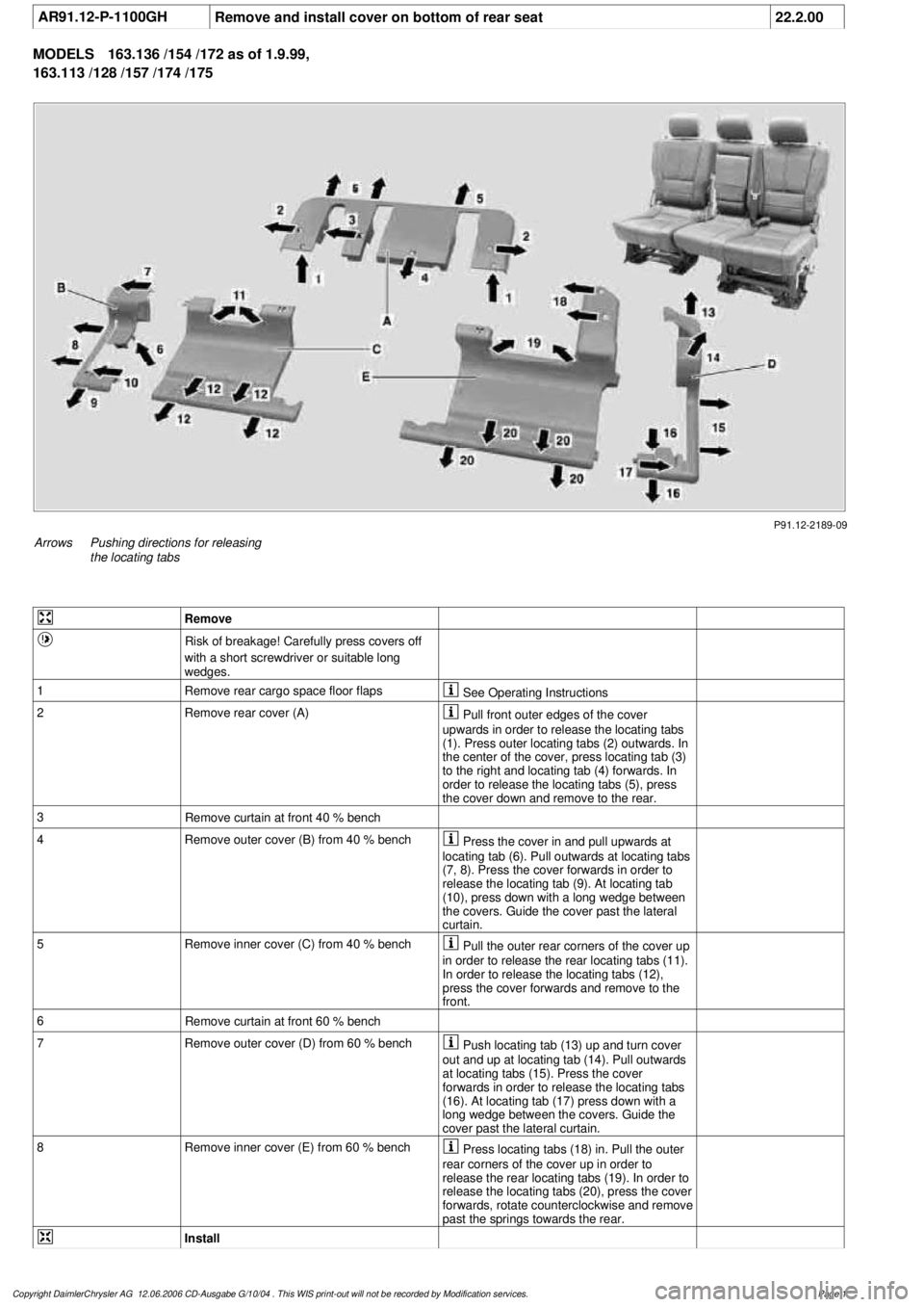
AR91.12-P-1100GH
Remove and install cover on bottom of rear seat
22.2.00
MODELS
163.136 /154 /172 as of 1.9.99,
163.113 /128 /157 /174 /175
P91.12-2189-09
Arrows
Pushing directions for releasing
the locating tabs
Remove
Risk of breakage! Carefully press covers off
with a short screwdriver or suitable long
wedges.
1
Remove rear cargo space floor flaps
See Operating Instructions
2Remove rear cover (A)
Pull front outer edges of the cover
upwards in order to release the locating tabs
(1). Press outer locating tabs (2) outwards. In
the center of the cover, press locating tab (3)
to the right and locating tab (4) forwards. In
order to release the locating tabs (5), press
the cover down and remove to the rear.
3
Remove curtain at front 40 % bench
4
Remove outer cover (B) from 40 % bench
Press the cover in and pull upwards at
locating tab (6). Pull outwards at locating tabs
(7, 8). Press the cover forwards in order to
release the locating tab (9). At locating tab
(10), press down with a long wedge between
the covers. Guide the cover past the lateral
curtain.
5
Remove inner cover (C) from 40 % bench
Pull the outer rear corners of the cover up
in order to release the rear locating tabs (11).
In order to release the locating tabs (12),
press the cover forwards and remove to the
front.
6
Remove curtain at front 60 % bench
7
Remove outer cover (D) from 60 % bench
Push locating tab (13) up and turn cover
out and up at locating tab (14). Pull outwards
at locating tabs (15). Press the cover
forwards in order to release the locating tabs
(16). At locating tab (17) press down with a
long wedge between the covers. Guide the
cover past the lateral curtain.
8
Remove inner cover (E) from 60 % bench
Press locating tabs (18) in. Pull the outer
rear corners of the cover up in order to
release the rear locating tabs (19). In order to
release the locating tabs (20), press the cover
forwards, rotate counterclockwise and remove
past the springs towards the rear.
Install
Copyright DaimlerChrysler AG 12.06.2006 CD-Ausgabe G/10/04 . This WIS print-out will not be recorde
d by Modification services.
Page 1
Page 1492 of 4133

9
Install inner cover (E) at 60 % bench
Insert cover past the springs from the rear
and rotate into position in a clockwise
direction. Insert locating tabs (19). Press the
front cover down and reset so that locating
tabs (20) engage. Press rear cover down until
locating tabs (18) engage.
10
Install outer cover (D) at 60 % bench
Guide the cover past the lateral curtain.
Insert locating tab (17), push front cover down
and reset so that locating tabs (16) engage.
Press the outer edge of the cover down and
insert lateral locating tabs (15). Raise rear
cover on the inside, press down until locating
tab (14) and rear locating tab (13) engage.
11
Install curtain at front 60 % bench
12
Install inner cover (C) at 40 % bench
Insert cover from the front and insert
locating tabs (11). Press the front cover down
and reset so that locating tabs (12) engage.
13
Install outer cover (B) at 40 % bench
Guide the cover past the lateral curtain.
Insert locating tab (10), push front cover down
and reset so that locating tab (9) engages.
Press the outer edge of the cover down and
insert lateral locating tabs (8). Insert locating
tab (7), push cover down at locating tab (6)
and engage.
14
Install curtain at front 40 % bench
15
Install rear cover (A)
Insert cover from the rear and press down
and forwards so that locating tabs (5) engage.
Press front ends of the cover down, so that
locating tabs (2, 3, 4) engage. Insert locating
tabs (1) into covers (C, E).
Copyright DaimlerChrysler AG 12.06.2006 CD-Ausgabe G/10/04 . This WIS print-out will not be recorde
d by Modification services.
Page 2
Page 1507 of 4133
DATA TRANSFER, FUNCTION - GF82.00-P-2000A
MODEL 129 as of 1.6.98, 163, 168 as of 1.9.98, 170, 202 as of 1.6.98, 203, 208, 210 as of 1.6.98, 215, 220
The Digital Data Bus (D2B) contains the master unit, e.g. the radio (A2) except for model 129, and model 202,
which triggers all the components in the Digital Data Bus system (D2B). The master unit also serves as an
interface (Gateway) to the CAN interior (CAN-B). For this purpose, signals arriving at the master unit are
converted so that they can be transmitted from the Digital Data Bus (D2B) to the CAN interior (CAN B) and
vice versa. Moreover, the master unit serves as a timing circuit which provides the clock pulse with which the
information frames are transferred on the Digital Data Bus (D2B). A frame consists of 2 subframes. A series of
many data frames contains the complete information for proper operation of the components located at the
Digital Data Bus (D2B). The conversion of optical pulses into electrical signals and vice versa is done by
transmitter and receiver diodes, that are integrated into each component. Each of the components receives or
transmits the electrical signals from the chip of the Digital Data Bus system (D2B) as a "D2B log". Source data
and control data are transmitted.
The source data are transferred synchronously, for example as present on a music CD, as 32 bit blocks into the
subframes. By contrast, control data are transferred asynchronously. They are divided up (2 bits per subframe)
and distributed over several subframes. The control data are provided with an address, which indicates for
which components the data are intended in the Digital Data Bus (D2B). The individual data packages are joined
together again in the components and they can then be processed. A data frame can therefore contain highly
differing types of information (source and control data from all components mounted in the digital data bus
(D2B)). The transmission and reception diodes as well as the digital data bus (D2B) chip are switched off when
not required in order to reduce the quiescent current (sleep mode). Switch-off is accomplished immediately
when the master unit or circuit 15 is switched off. After restart, the digital data bus system (D2B) can be
activated either by the components or by the master unit by means of an electrical signal in the wake-up line for
optical data transmission.
Regardless whether the information is intended for a component, it feeds an edited light signal back into the
digital data bus (D2B) at full intensity (repeater function).
WAKE-UP, FUNCTION - GF82.00-P-2001A
MODEL 129 as of 1.6.98, 163, 168 as of 1.9.98, 170, 202 as of 1.6.98, 203, 208, 210 as of 1.6.98, 215, 220
Normal wake-up
Digital data bus (D2B), function GF82.00-P-0001A
Data transfer, function GF82.00-P-2000A
Wake-up, function GF82.00-P-2001A
Survey of system components, digital
data bus (D2B),
location/task/design/function GF82.00-P-9999A
Wake-up, function GF82.00-P-2001A
2001 Mercedes-Benz ML320
1998-2005 ACCESSORIES & BODY, CAB Electrical System - Body - 163 Chassis
me
Saturday, October 02, 2010 3:30:04 PMPage 12 © 2006 Mitchell Repair Information Company, LLC.
Page 1578 of 4133
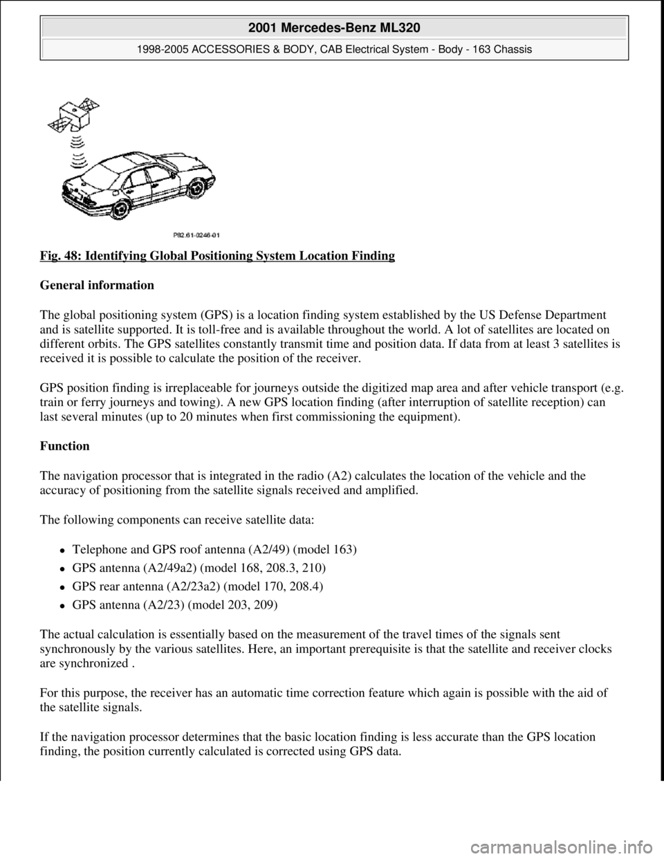
Fig. 48: Identifying Global Positioning System Location Finding
General information
The global positioning system (GPS) is a location finding system established by the US Defense Department
and is satellite supported. It is toll-free and is available throughout the world. A lot of satellites are located on
different orbits. The GPS satellites constantly transmit time and position data. If data from at least 3 satellites is
received it is possible to calculate the position of the receiver.
GPS position finding is irreplaceable for journeys outside the digitized map area and after vehicle transport (e.g.
train or ferry journeys and towing). A new GPS location finding (after interruption of satellite reception) can
last several minutes (up to 20 minutes when first commissioning the equipment).
Function
The navigation processor that is integrated in the radio (A2) calculates the location of the vehicle and the
accuracy of positioning from the satellite signals received and amplified.
The following components can receive satellite data:
Telephone and GPS roof antenna (A2/49) (model 163)
GPS antenna (A2/49a2) (model 168, 208.3, 210)
GPS rear antenna (A2/23a2) (model 170, 208.4)
GPS antenna (A2/23) (model 203, 209)
The actual calculation is essentially based on the measurement of the travel times of the signals sent
synchronously by the various satellites. Here, an important prerequisite is that the satellite and receiver clocks
are synchronized .
For this purpose, the receiver has an automatic time correction feature which again is possible with the aid of
the satellite signals.
If the navigation processor determines that the basic location finding is less accurate than the GPS location
findin
g, the position currently calculated is corrected using GPS data.
2001 Mercedes-Benz ML320
1998-2005 ACCESSORIES & BODY, CAB Electrical System - Body - 163 Chassis
me
Saturday, October 02, 2010 3:30:05 PMPage 83 © 2006 Mitchell Repair Information Company, LLC.