Page 631 of 4133

164
Starting and turning off the engine
Te ch n ica l
data
Instruments
and controls Operation
Driving Instrument
cluster display Practical hints Car care Index
Starting and turning off the engine
Before starting
Ensure that parking brake is engaged and that selector
lever is in position “P” or “N”. Turn key in steering lock
to position 2. The charge indicator lamp should come on.
Starting
Do not depress accelerator.
Briefly turn key in steering lock clockwise to the stop
and release. The starter will engage until the engine is
running.
If engine will not run, and the starting procedure stops,
turn key completely to the left and repeat starting the
engine.
After several unsuccessful attempts, have the system
checked at the nearest authorized Mercedes-Benz Light
Truck Center.
A starting procedure can be interrupted by turning the
key to steering lock position 0. Important!
Due to the installed starter non-repeat feature, the key
must be turned completely to the left before attempting
to start the engine again.
In areas where temperatures frequently drop below -4 °F
(-20 °C) we recommend that an engine block heater be
installed. Your authorized Mercedes-Benz Light Truck
Center will advise you on this subject.
Note:
In case the engine cannot be started and the
messages Á and î are shown in the odometer
display field, the system is not operational. Contact an
authorized Mercedes-Benz Light Truck Center or call
1-800-FOR-MERCedes (in the USA), or 1-800-387-0100
(in Canada).
Turning off
Turn the key in the steering lock to position 0 to stop the
engine.
The key can only be removed with the selector lever in
position “P”.
Page 696 of 4133
229
Fuses
Te ch n ica l
data
Instruments
and controls Operation Driving
Instrument
cluster display Practical hints
Car care Index
Fuse box in engine compartment
1 Fuse box in engine compartment
To gain access to the fuse box, release clamps
(arrows), lift the fuse box cover (1) up and remove it.
To close the fuse box, engage back end of cover,
close, and secure with clamps. Auxiliary fuse box in front passenger footwell
2 Auxiliary fuse box in front passenger compartment
To gain access to the fuse box, turn both locks (3)
90 ° counterclockwise and remove cover in direction
of arrow.
To close the fuse box, engage back end of cover, slide
the cover towards vehicle front and secure by
turning both locks (3) clockwise to the stop.
1
Page 719 of 4133

252
Battery
Te ch n ica l
data
Instruments
and controls Operation Driving
Instrument
cluster display Practical hints
Car care Index
Therefore, we strongly recommend that you have the
battery charge checked frequently, and corrected if
necessary, especially if you use the vehicle less than
approximately 200 miles (300 km) per month,
mostly for short distance trips, or if it is not used for
long periods of time.
Only charge a battery with a battery charger after the
battery has been disconnected from the vehicle’s
electrical circuit.
Always disconnect the battery negative lead first and
connect last.
When removing and connecting the battery, always
make sure that all electrical consumers are off and the
key is in steering lock position 0. The battery must
always be securely installed when the vehicle is in
operation. During removal and installation always
protect the disconnected battery positive (+) terminal
with the cover attached to the battery.
While the engine is running the battery terminal clamps
must not be loosened or detached, otherwise the
generator and other electronic components would be
damaged. Note:
After reconnecting the battery also set the clock in
instrument cluster (see page 80), set date in trip
computer (see page 83), resynchronize the sliding / pop-
up roof (see page 272), the Skyview Top (see page 273)
and the electronic stability program (ESP) (see
page 206).
Battery recycling
Batteries contain material that can harm the
environment with improper disposal.
Large 12 Volt storage batteries contain lead.
Recycling of batteries is the preferred method of
disposal.
Many states require sellers of batteries to accept old
batteries for recycling.
Page 731 of 4133
264
Exterior lamps
Te ch n ica l
data
Instruments
and controls Operation Driving
Instrument
cluster display Practical hints
Car care Index
Parking, standing, side marker and turn signal lamp
115 6 N A ( 3 2 / 4 c p b u l b )
Open hood.
Twist bulb socket (4) counterclockwise and pull out.
Push bulb into socket, turn counterclockwise and
remove.
Insert new bulb in socket, push in and twist clockwise.
Reinstall bulb socket. Bulbs for auxiliary fog lamp
(optional)
H3 U (55 W)
Open hood.
Remove cover (9). Unhook clamping ring and remove
bulb. Pull off electrical connector.
Insert new bulb in socket (seating properly in cutouts of
bulb socket), and mount clamping ring. Reinstall and
push electrical connector on securely.
Reinstall cover (9).
Page 733 of 4133
266
Exterior lamps
Te ch n ica l
data
Instruments
and controls Operation Driving
Instrument
cluster display Practical hints
Car care Index
Pull off electrical connector (2).
Squeeze tabs (3) together and remove bulb holder.
Push bulb into socket, turn counterclockwise and
remove.
Insert new bulb in socket, push in and twist clockwise.
Reinstall bulb holder.
Reinstall electrical connector (2).
Reinstall taillamp. Turn signal lamp, side
(168 [3 cp bulb])
Carefully slide lamp slightly towards rear (arrow), lift
away its front end first, then remove lamp from panel.
Twist bulb socket counterclockwise and pull out. Pull
bulb out of socket.
Insert new bulb in socket. Reinstall bulb socket.
To reinstall lamp, set rear end of lamp into panel and let
front end snap into place.
Page 734 of 4133
267
Exterior lamps
Te ch n ica l
data
Instruments
and controls Operation Driving
Instrument
cluster display Practical hints
Car care Index
License plate lamps
(C 5 W [tubular] bulb)
Remove both securing screws, remove lamp and take
out bulb. High mounted stop lamp
(1073 [32 cp bulb])
To replace bulb, squeeze both sides (1, arrows) of cover,
fold forward and remove.
Press tab (2, arrow) on reflector and remove reflector.
Press bulb down, turn counterclockwise and remove.
Insert new bulb in socket, push in and twist clockwise.
Reinstall reflector.
Position tabs of cover in slots (3, arrows) and reinstall
cover until properly seated.
P82.10-2347-26
P82.10-2346-26
Page 736 of 4133

269
Exterior lamps
Te ch n ica l
data
Instruments
and controls Operation Driving
Instrument
cluster display Practical hints
Car care Index
5. (High beams on):
Simultaneously turn adjusting screws (1 and 2 on
page 261 or 262) counterclockwise to adjust
headlamp downward, clockwise upward) equally
until bubble in the level (7 on page 261) is centered
on the “0” mark.
Graduations:
screw 1: 0.50 ° pitch,
screw 2: 0.67 ° pitch.
6. Horizontal headlamp aim (High beams on): Turn adjusting screw (2) (left headlamp:
counterclockwise to adjust to the left, clockwise to
the right [right headlamp in opposite direction])
until the headlamp (high beam pattern) is centered
about the vertical centerline (1) as shown.
The left and right headlamps must be adjusted
individually. 7. For proper aim, the indicator (8 on page 261) should
align with the “0” mark after horizontal adjustment.
Graduations: 0.33 ° pitch.
Note:
If it is not possible to obtain a proper headlamp
adjustment, have the system checked at your authorized
Mercedes-Benz Light Truck Center.
Page 739 of 4133

272
Emergency operation of sliding/pop-up roof
Te ch n ica l
data
Instruments
and controls Operation Driving
Instrument
cluster display Practical hints
Car care Index
Emergency operation of sliding/pop-up roof
The sliding / pop-up roof can be opened or closed
manually should an electrical malfunction occur.
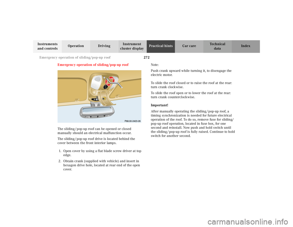
The sliding / pop-up roof drive is located behind the
cover between the front interior lamps.
1. Open cover by using a f lat blade screw driver at top edge.
2. Obtain crank (supplied with vehicle) and insert in hexagon drive hole, located at rear end of the open
cover. Note:
Push crank upward while turning it, to disengage the
electric motor.
To slide the roof closed or to raise the roof at the rear:
turn crank clockwise.
To slide the roof open or to lower the roof at the rear:
turn crank counterclockwise.
Important!
After manually operating the sliding / pop-up roof, a
timing synchronization is needed for future electrical
operation of the roof. To do so, remove fuse for sliding/
pop-up roof operation, located in fuse box, for one
second and reinstall. Now push and hold switch until
the sliding / pop-up roof is fully raised. Continue to hold
switch for another second.
R ESETM O
DEM OD
E