1997 MERCEDES-BENZ ML320 fuse diagram
[x] Cancel search: fuse diagramPage 1688 of 4133
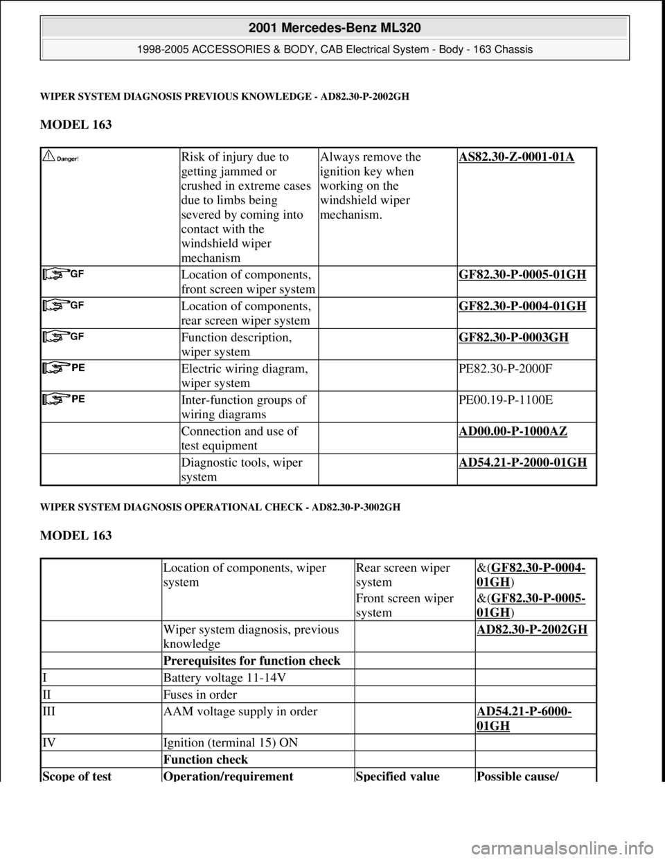
WIPER SYSTEM DIAGNOSIS PREVIOUS KNOWLEDGE - AD82.30-P-2002GH
MODEL 163
WIPER SYSTEM DIAGNOSIS OPERATIONAL CHECK - AD82.30-P-3002GH
MODEL 163
Risk of injury due to
getting jammed or
crushed in extreme cases
due to limbs being
severed by coming into
contact with the
windshield wiper
mechanismAlways remove the
ignition key when
working on the
windshield wiper
mechanism.AS82.30-Z-0001-01A
Location of components,
front screen wiper system GF82.30-P-0005-01GH
Location of components,
rear screen wiper system GF82.30-P-0004-01GH
Function description,
wiper system GF82.30-P-0003GH
Electric wiring diagram,
wiper system PE82.30-P-2000F
Inter-function groups of
wiring diagrams PE00.19-P-1100E
Connection and use of
test equipment AD00.00-P-1000AZ
Diagnostic tools, wiper
system AD54.21-P-2000-01GH
Location of components, wiper
systemRear screen wiper
system&(GF82.30-P-0004-
01GH)
Front screen wiper
system&(GF82.30-P-0005-
01GH)
Wiper system diagnosis, previous
knowledge AD82.30-P-2002GH
Prerequisites for function check
IBattery voltage 11-14V
IIFuses in order
IIIAAM voltage supply in order AD54.21-P-6000-
01GH
IVIgnition (terminal 15) ON
Function check
Scope of test Operation/requirement Specified value Possible cause/
2001 Mercedes-Benz ML320
1998-2005 ACCESSORIES & BODY, CAB Electrical System - Body - 163 Chassis
me
Saturday, October 02, 2010 3:30:07 PMPage 193 © 2006 Mitchell Repair Information Company, LLC.
Page 1712 of 4133
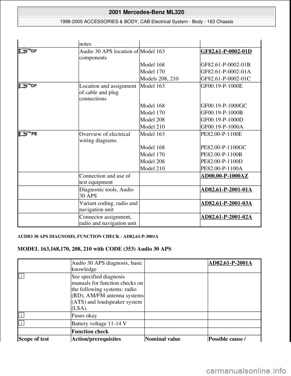
AUDIO 30 APS DIAGNOSIS, FUNCTION CHECK - AD82.61-P-3001A
MODEL 163,168,170, 208, 210 with CODE (353) Audio 30 APS
notes
Audio 30 APS location of
componentsModel 163GF82.61-P-0002-01D
Model 168GF82.61-P-0002-01B
Model 170GF82.61-P-0002-01A
Models 208, 210GF82.61-P-0002-01C
Location and assignment
of cable and plug
connectionsModel 163GF00.19-P-1000E
Model 168GF00.19-P-1000GC
Model 170GF00.19-P-1000B
Model 208GF00.19-P-1000D
Model 210GF00.19-P-1000A
Overview of electrical
wiring diagramsModel 163PE82.00-P-1100E
Model 168PE82.00-P-1100GC
Model 170PE82.00-P-1100B
Model 208PE82.00-P-1100D
Model 210PE82.00-P-1100A
Connection and use of
test equipment AD00.00-P-1000AZ
Diagnostic tools, Audio
30 APS AD82.61-P-2001-01A
Variant coding, radio and
navigation unit AD82.61-P-2001-03A
Connector assignment,
radio and navigation unit AD82.61-P-2001-02A
Audio 30 APS diagnosis, basic
knowledge AD82.61-P-2001A
See specified diagnosis
manuals for function checks on
the following systems: radio
(RD), AM/FM antenna systems
(ATS) and loudspeaker system
(LSA).
Fuses okay
Battery voltage 11-14 V
Function check
Scope of test Action/prerequisites Nominal value Possible cause /
2001 Mercedes-Benz ML320
1998-2005 ACCESSORIES & BODY, CAB Electrical System - Body - 163 Chassis
me
Saturday, October 02, 2010 3:30:08 PMPage 217 © 2006 Mitchell Repair Information Company, LLC.
Page 1741 of 4133
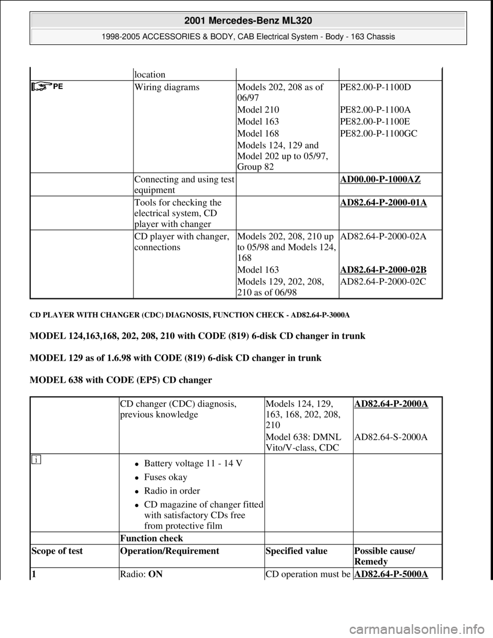
CD PLAYER WITH CHANGER (CDC) DIAGNOSIS, FUNCTION CHECK - AD82.64-P-3000A
MODEL 124,163,168, 202, 208, 210 with CODE (819) 6-disk CD changer in trunk
MODEL 129 as of 1.6.98 with CODE (819) 6-disk CD changer in trunk
MODEL 638 with CODE (EP5) CD changer
location
Wiring diagramsModels 202, 208 as of
06/97PE82.00-P-1100D
Model 210PE82.00-P-1100A
Model 163PE82.00-P-1100E
Model 168PE82.00-P-1100GC
Models 124, 129 and
Model 202 up to 05/97,
Group 82
Connecting and using test
equipment AD00.00-P-1000AZ
Tools for checking the
electrical system, CD
player with changer AD82.64-P-2000-01A
CD player with changer,
connectionsModels 202, 208, 210 up
to 05/98 and Models 124,
168AD82.64-P-2000-02A
Model 163AD82.64-P-2000-02B
Models 129, 202, 208,
210 as of 06/98AD82.64-P-2000-02C
CD changer (CDC) diagnosis,
previous knowledgeModels 124, 129,
163, 168, 202, 208,
210AD82.64-P-2000A
Model 638: DMNL
Vito/V-class, CDCAD82.64-S-2000A
Battery voltage 11 - 14 V
Fuses okay
Radio in order
CD magazine of changer fitted
with satisfactory CDs free
from protective film
Function check
Scope of test Operation/Requirement Specified value Possible cause/
Remedy
1 Radio: ON CD operation must be AD82.64-P-5000A
2001 Mercedes-Benz ML320
1998-2005 ACCESSORIES & BODY, CAB Electrical System - Body - 163 Chassis
me
Saturday, October 02, 2010 3:30:08 PMPage 246 © 2006 Mitchell Repair Information Company, LLC.
Page 1836 of 4133
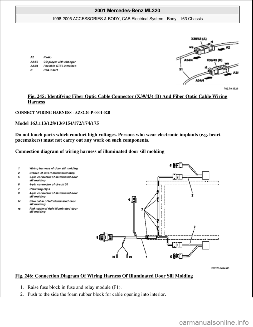
Fig. 245: Identifying Fiber Optic Cable Connector (X39/43) (B) And Fiber Optic Cable Wiring
Harness
CONNECT WIRING HARNESS - AZ82.20-P-0001-02B
Model 163.113/128/136/154/172/174/175
Do not touch parts which conduct high voltages. Persons who wear electronic implants (e.g. heart
pacemakers) must not carry out any work on such components.
Connection diagram of wiring harness of illuminated door sill molding
Fig. 246: Connection Diagram Of Wiring Harness Of Illuminated Door Sill Molding
1. Raise fuse block in fuse and relay module (F1).
2. Push to the side the foam rubber block for cable openin
g into interior.
2001 Mercedes-Benz ML320
1998-2005 ACCESSORIES & BODY, CAB Electrical System - Body - 163 Chassis
me
Saturday, October 02, 2010 3:30:11 PMPage 341 © 2006 Mitchell Repair Information Company, LLC.
Page 2223 of 4133
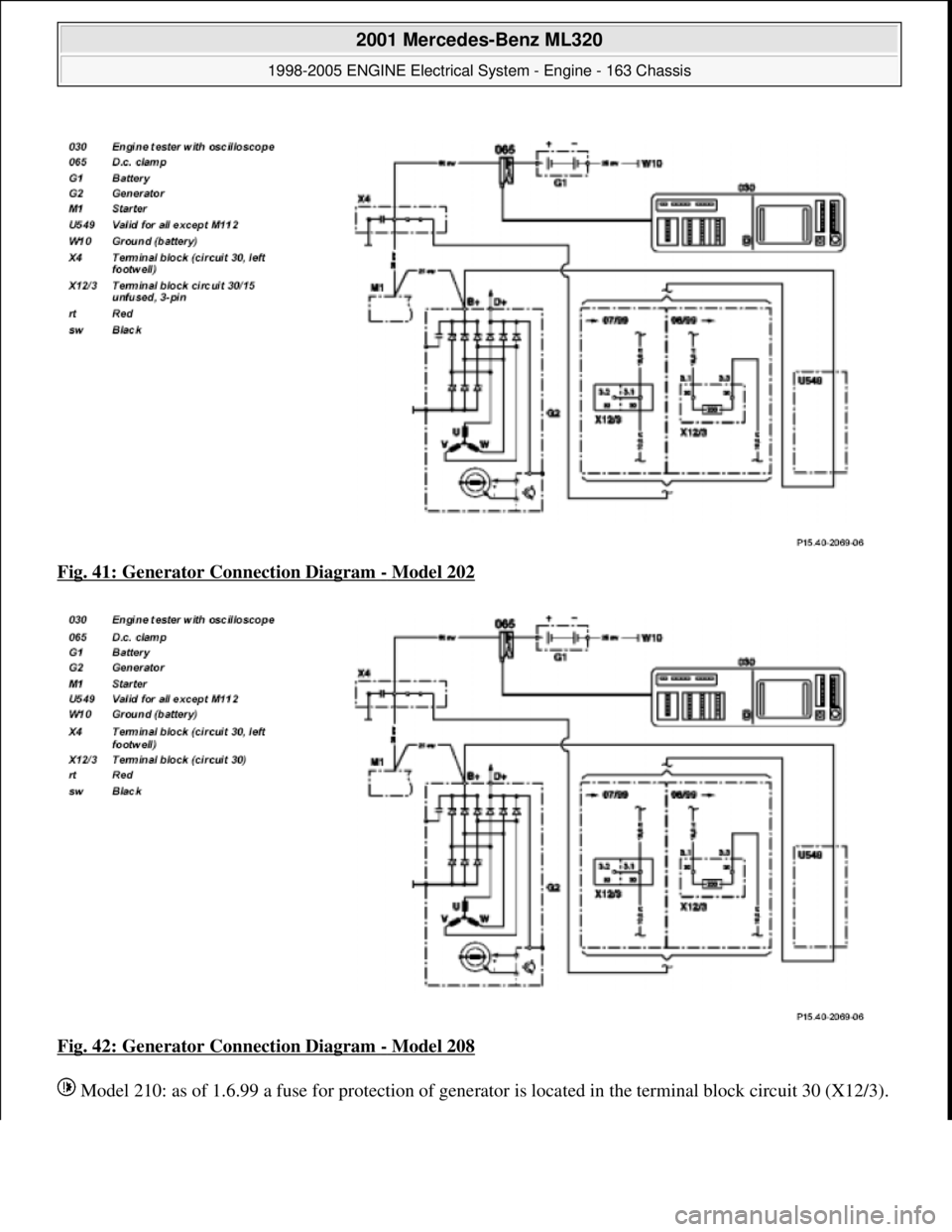
Fig. 41: Generator Connection Diagram - Model 202
Fig. 42: Generator Connection Diagram
- Model 208
Model 210: as of 1.6.99 a fuse for protection of
generator is located in the te rminal block circuit 30 (X12/3).
2001 Mercedes-Benz ML320
1998-2005 ENGINE Electrical System - Engine - 163 Chassis
me
Saturday, October 02, 2010 3:18:55 PMPage 69 © 2006 Mitchell Repair Information Company, LLC.
Page 3220 of 4133
FUNCTIONAL TEST PREPARATION
1. Check condition of fuses F16, F41, F43 and F44. See WIRING DIAGRAMS . Repair and/or replace
fuses and necessary.
2. Turn ignition on. Locate in-vehicle temperature sensor aspirator blower vent grille above anti-theft
indicator light. Place a half-inch square of tissue paper over aspirator blower vent grille. If paper stays on
vent grille, go to next step. If paper does not stay on vent grille, correct insufficient aspirator blower
ventilation.
3. Put shift lever in "P" and engage parking brake. Run engine at idle until it reaches normal operating
temperature, about 176°F (80°C). Ensure ambient (outside) temperature is greater than 58°F (15°C).
4. Manually open center and side air outlets. Ensure recirculation button is not depressed. Set blower speed
knob to position No. 1.
FUNCTION TEST
Defrost Mode
To check operation in defrost mode, set temperature selector knob to White range (vertical). Set mode control
knob to 12-o'clock position (vertical). Ensure A/C button indicator is illuminated. Air will vent from defrost and
center outlets and A/C compressor will engage. If operation is not as specified, perform the following in order:
Check voltage supply circuit Z50/2 between No. 16 fuse (15-amp) and connected components. See
VOLTAGE SUPPLY CIRCUIT Z50/2
under ELECTRICAL TESTS.
Check ground circuit. See GROUND CIRCUIT Z50/4 under ELECTRICAL TESTS.
Check in-vehicle temperature sensor signal voltage. See IN-VEHICLE TEMPERATURE SENSOR
under ELECTRICAL TESTS.
Check in-vehicle temperature sensor signal resistance. See IN-VEHICLE TEMPERATURE SENSOR
under ELECTRICAL TESTS.
Check icing protection temperature sensor signal voltage. See ICING PROTECTION
TEMPERATURE SENSOR under ELECTRICAL TESTS.
Check icing protection temperature sensor resistance. See ICING PROTECTION TEMPERATURE
SENSOR under ELECTRICAL TESTS.
Check activation voltage during temperature reduction. See ACTIVATION VOLTAGE
TEMPERATURE under ELECTRICAL TESTS.
Check activation voltage during temperature increase. See ACTIVATION VOLTAGE
TEMPERATURE under ELECTRICAL TESTS.
Check blend air flap actuator motor operation voltage. See BLEND AIR FLAP ACTUATOR MOTOR
under ELECTRICAL TESTS.
Check blend air flap actuator motor resistance. See BLEND AIR FLAP ACTUATOR MOTOR under
ELECTRICAL TESTS.
Check A/C button activation. See A/C BUTTON under ELECTRICAL TESTS.
Check A/C pressure switch. See A/C REFRIGERANT PRESSURE SWITCH under ELECTRICAL NOTE: Function test steps must be performed in order given.
2001 Mercedes-Benz ML320
2000-01 MANUAL A/C-HEATER SYSTEMS ML 320, ML 430 & ML 55
me
Saturday, October 02, 2010 3:25:10 PMPage 9 © 2006 Mitchell Repair Information Company, LLC.
Page 3221 of 4133
TESTS.
Normal Ventilation In Regulating Mode
To check normal ventilation in regulating mode, set temperature selector knob to White range (vertical). Set
mode control knob to 4-o'clock position. Ensure A/C button indicator is illuminated. Air will vent from upper
and lower outlets and A/C compressor will engage. Ambient air will flow from center outlet and coolant
circulation pump will operate. If operation is not as specified, perform the following in order:
Check A/C button activation. See A/C BUTTON under ELECTRICAL TESTS.
Check A/C pressure switch. See A/C REFRIGERANT PRESSURE SWITCH under ELECTRICAL
TESTS.
Economy Setting Not In Heating Mode
To check economy setting without heating mode activated, set temperature selector knob to Blue range. Set
mode control knob to the 9-o'clock position. Ensure A/C button indicator is not illuminated. Ambient air will
flow from center outlet and A/C compressor will NOT be engaged. If operation is not as specified, perform the
following:
Check A/C button activation. See A/C BUTTON under ELECTRICAL TESTS.
Economy Setting In Heating Mode
To check economy setting with heating mode activated, set temperature selector knob to Red range. Set mode
control knob to the 4-o'clock position. Ensure A/C button indicator is not illuminated. Heated air will flow from
lower, upper and center outlets and A/C compressor will NOT be engaged. If operation is not as specified,
perform the following:
Check A/C button activation. See A/C BUTTON under ELECTRICAL TESTS.
Recirculation Mode
To check recirculation mode, press fresh/recirculation button. Ensure fresh/recirculation indicator is
illuminated. Set blower speed knob to position No. 4. Blower fan noise will increase noticeably. If operation is
not as specified, check wiring between recirculated air flap element, heater-A/C switch and No. 16 fuse (15-
amp).
ELECTRICAL TESTS
Voltage Supply Circuit Z50/2
1. Connect socket box to A/C push button control unit and wiring harness. See CONNECTING TEST
EQUIPMENT . Turn ignition on, with engine off. Connect voltmeter positive lead to socket box terminal
No. 7 and negative lead to terminal No. 9.
2. Voltage should be 11-14 volts. If voltage is not as specified, check voltage supply circuit Z50/2 between
No. 16 fuse (15-amp) and connected components. See WIRING DIAGRAMS
. Repair as necessary.
2001 Mercedes-Benz ML320
2000-01 MANUAL A/C-HEATER SYSTEMS ML 320, ML 430 & ML 55
me
Saturday, October 02, 2010 3:25:10 PMPage 10 © 2006 Mitchell Repair Information Company, LLC.
Page 3224 of 4133
blend air flap actuator motor.
6. Turn ignition off. Disconnect test cable from A/C push button control unit. Connect ohmmeter positive
lead to socket box terminal No. 1 and negative lead to terminal No. 8. Resistance should be 120 ohms.
7. If resistance is not as specified, check blend air flap actuator motor circuits. See WIRING DIAGRAMS
.
Repair as necessary. If circuits are okay, replace blend air flap actuator motor.
A/C Button
1. Connect socket box to A/C push button control unit and wiring harness. See CONNECTING TEST
EQUIPMENT . Connect voltmeter positive lead to socket box terminal No. 10 and negative lead to
terminal No. 9.
2. Turn ignition on. Depress A/C button switch to on position and set blower speed knob to position No. 4.
Ensure A/C button indicator is illuminated. Voltage should be less than one volt. Depress A/C button
switch to off position with A/C button indicator not illuminated or set blower speed knob to off position.
Voltage should be 11-14 volts.
3. If voltage is as specified, go to next step. If voltage is not as specified, check A/C button wiring harness
circuits. See WIRING DIAGRAMS
. Repair as necessary. If circuits are okay, replace A/C button
switch.
4. Turn ignition on. Depress A/C button switch to on position and set blower speed knob to position No. 4.
Ensure A/C button indicator is illuminated. Connect voltmeter positive lead to socket box terminal No. 4
and negative lead to terminal No. 9. Voltage should be more than 3.0 volts.
5. Connect Fused Jumper Wire (124 589 37 63 00) between socket box terminals No. 4 and 11. Depress A/C
button switch to on position and set blower speed knob to position No. 4. Ensure A/C button indicator is
illuminated. Measure voltage. Voltage should be less than one volt.
6. If voltage is not as specified, check A/C button wiring harness circuits. See WIRING DIAGRAMS
.
Repair as necessary. If circuits are okay, replace A/C button switch.
A/C Refrigerant Pressure Switch
1. Turn ignition off. Disconnect refrigerant pressure sensor connector. Turn ignition on. Connect voltmeter
positive lead to pressure sensor harness connector terminal "B" (Pink wire) and negative lead to terminal
"A" (Tan wire). Voltage should be 4.75-5.25 volts.
2. If voltage is as specified, replace A/C refrigerant pressure sensor. If voltage is not as specified, check
wiring harness between refrigerant pressure sensor and All Activity Module (AAM). See WIRING
DIAGRAMS . Repair as necessary. If circuits are okay, replace AAM and retest A/C system.
Outside Temperature Sensor
1. Connect socket box to A/C push button control unit and wiring harness. See CONNECTING TEST
EQUIPMENT . Turn ignition off. Connect ohmmeter positive lead to socket box terminal No. 12 and
negative lead to terminal No. 3.
2. Disconnect test cable from A/C push button control unit. See OUTSIDE TEMPERATURE SENSOR
RESISTANCE table. If resistance is not as specified, check wiring harness between outside temperature
sensor and A/C push button control unit. See WIRING DIAGRAMS
. Repair as necessary. If wiring
harness is okay, replace outside temperature sensor.
2001 Mercedes-Benz ML320
2000-01 MANUAL A/C-HEATER SYSTEMS ML 320, ML 430 & ML 55
me
Saturday, October 02, 2010 3:25:10 PMPage 13 © 2006 Mitchell Repair Information Company, LLC.