1997 MERCEDES-BENZ ML320 fuses
[x] Cancel search: fusesPage 16 of 4133
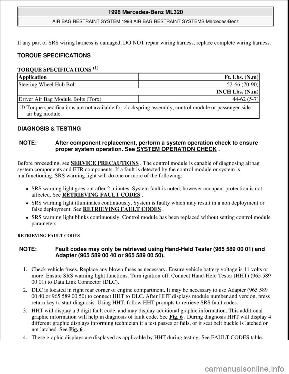
If any part of SRS wiring harness is damaged, DO NOT repair wiring harness, replace complete wiring harness.
TORQUE SPECIFICATIONS
TORQUE SPECIFICATIONS
(1)
DIAGNOSIS & TESTING
Before proceeding, see SERVICE PRECAUTIONS
. The control module is capable of diagnosing airbag
system components and ETR components. If a fault is detected by the control module or system is
malfunctioning, SRS warning light will do one or more of the following:
SRS warning light goes out after 2 minutes. System fault is noted, however occupant protection is not
affected. See RETRIEVING FAULT CODES
.
SRS warning light illuminates continuously. System is faulty which may result in a non deployment or
false deployment. See RETRIEVING FAULT CODES
.
SRS warning light blinks continuously. Control module has been replaced without setting control module
parameters.
RETRIEVING FAULT CODES
1. Check vehicle fuses. Replace any blown fuses as necessary. Ensure vehicle battery voltage is 11 volts or
more. Ensure SRS warning light functions. Turn ignition off. Connect Hand-Held Tester (HHT) (965 589
00 01) to Data Link Connector (DLC).
2. DLC is located in right rear corner of engine compartment. It may be necessary to use Adapter (965 589
00 40 or 965 589 00 50) to connect HHT to DLC. After HHT displays module number and version, press
return key to start diagnosis. Using HHT, follow HHT prompts to retrieve SRS fault codes.
3. HHT will display a 3 digit fault code, and may display additional graphic information. This additional
graphic information will help in diagnosis of fault code. See Fig. 6
. During diagnosis HHT will display 4
different graphic displays informing technician if a test passes or fails, or if seat belt buckle is latched or
not latched. See Fig. 6
.
4. These
graphic displays are displayed as applicable by HHT during testing. See FAULT CODES table.
ApplicationFt. Lbs. (N.m)
Steering Wheel Hub Bolt52-66 (70-90)
INCH Lbs. (N.m)
Driver Air Bag Module Bolts (Torx)44-62 (5-7)
(1)Torque specifications are not available for clockspring assembly, control module or passenger-side
air bag module.
NOTE: After component replacement, perform a system operation check to ensure
proper system operation. See SYSTEM OPERATION CHECK
.
NOTE: Fault codes may only be retrieved using Hand-Held Tester (965 589 00 01) and
Adapter (965 589 00 40 or 965 589 00 50).
1998 Mercedes-Benz ML320
AIR BAG RESTRAINT SYSTEM 1998 AIR BAG RESTRAINT SYSTEMS Mercedes-Benz
me
Saturday, October 02, 2010 3:33:14 PMPage 16 © 2006 Mitchell Repair Information Company, LLC.
Page 54 of 4133

4 Contents
Practical hintsFirst aid kit .....................................228
Fuses ................................................228
Electrical outlet ..............................230
Stowing things in the vehicle ......230
Hood ................................................. 231
Checking engine oil level .............233
Automatic transmission
fluid level ...................................234
Engine oil consumption ................234
Coolant level ...................................234
Adding coolant ...........................235
Windshield washer/headlamp
cleaning system .........................236
Windshield and
headlamp washer fluid
mixing ratio ................................237Vehicle jack, wheel bolt
wrench and screwdriver ......... 237
Air pump ......................................... 239
Wheels ............................................ 240
Tire replacement ....................... 240
Rotating wheels ......................... 241
Spare wheel .................................... 242
Changing wheels ........................... 245
Tire inflation pressure ................. 250
Battery ............................................. 251
Jump starting ................................. 253
Towing the vehicle ........................ 255
Transmission selector lever,
manually unlocking .................. 259
Stranded vehicle ............................ 259Exterior lamps ................................260
Headlamp assembly ................... 261
Taillamp assemblies ..................265
Adjusting headlamp aim ...............268
Remote control
battery replacement .................270
Synchronizing
remote control ............................ 271
Emergency operation of
sliding/pop-up roof ...................272
Emergency operation of
Skyview Top ...............................273
Manual release for
fuel filler flap ............................. 274
Replacing wiper blades .................275
Roof rack ......................................... 276
Page 277 of 4133
227 Contents - Practical hints
Te ch n ica l
data Instruments
and controlsOperation DrivingInstrument
cluster displayPractical hintsCar care Index
Practical hintsFirst aid kit .....................................228
Fuses ................................................228
Electrical outlet ..............................230
Stowing things in the vehicle ......230
Hood ................................................. 231
Checking engine oil level .............233
Automatic transmission
fluid level ...................................234
Engine oil consumption ................234
Coolant level ...................................234
Adding coolant ...........................235
Windshield washer/headlamp
cleaning system .........................236
Windshield and
headlamp washer fluid
mixing ratio ................................237Vehicle jack, wheel bolt
wrench and screwdriver ......... 237
Air pump ......................................... 239
Wheels ............................................ 240
Tire replacement ....................... 240
Rotating wheels ......................... 241
Spare wheel .................................... 242
Changing wheels ........................... 245
Tire inflation pressure ................. 250
Battery ............................................. 251
Jump starting ................................. 253
Towing the vehicle ........................ 255
Transmission selector lever,
manually unlocking .................. 259
Stranded vehicle ............................ 259Exterior lamps ................................260
Headlamp assembly ................... 261
Taillamp assemblies ..................265
Adjusting headlamp aim ...............268
Remote control
battery replacement .................270
Synchronizing
remote control ............................ 271
Emergency operation of
sliding/pop-up roof ...................272
Emergency operation of
Skyview Top ...............................273
Manual release for
fuel filler flap ............................. 274
Replacing wiper blades .................275
Roof rack ......................................... 276
Page 278 of 4133
228 First aid kit
Te ch n ica l
data Instruments
and controlsOperation DrivingInstrument
cluster displayPractical hintsCar care Index
First aid kit
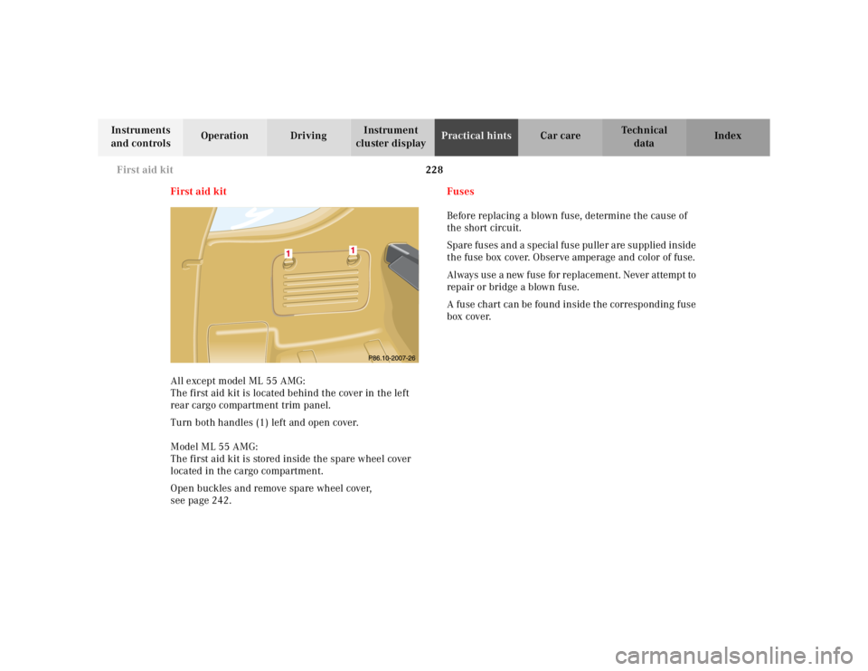
All except model ML 55 AMG:
The first aid kit is located behind the cover in the left
rear cargo compartment trim panel.
Turn both handles (1) left and open cover.
Model ML 55 AMG:
The first aid kit is stored inside the spare wheel cover
located in the cargo compartment.
Open buckles and remove spare wheel cover,
see page 242.Fuses
Before replacing a blown fuse, determine the cause of
the short circuit.
Spare fuses and a special fuse puller are supplied inside
the fuse box cover. Observe amperage and color of fuse.
Always use a new fuse for replacement. Never attempt to
repair or bridge a blown fuse.
A fuse chart can be found inside the corresponding fuse
box cover.
Page 279 of 4133
229 Fuses
Te ch n ica l
data Instruments
and controlsOperation DrivingInstrument
cluster displayPractical hintsCar care Index Fuse box in engine compartment
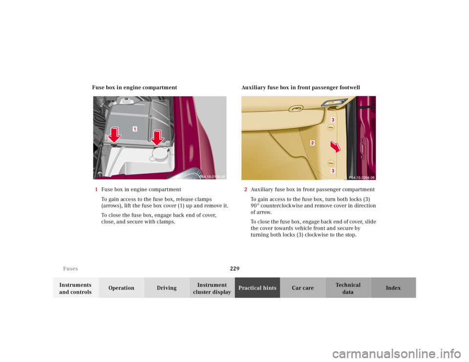
1Fuse box in engine compartment
To gain access to the fuse box, release clamps
(arrows), lift the fuse box cover (1) up and remove it.
To close the fuse box, engage back end of cover,
close, and secure with clamps.Auxiliary fuse box in front passenger footwell
2Auxiliary fuse box in front passenger compartment
To gain access to the fuse box, turn both locks (3)
90° counterclockwise and remove cover in direction
of arrow.
To close the fuse box, engage back end of cover, slide
the cover towards vehicle front and secure by
turning both locks (3) clockwise to the stop.
1
Page 354 of 4133
304 Index
Te ch n ica l
data Instruments
and controlsOperation DrivingInstrument
cluster displayPractical hints Car careIndex
FFirst aid kit .....................................................................228
Flexible service system (FSS) ........................................ 87
FSS indicator lamp ............................................ 79, 225
Floor plates
Removable .................................................................. 129
Fog lamp switch ........................................................ 92, 93
Four ETS
LOW RANGE – 4-ETS+ .............................................204
Malfunction indicator lamp ..................................... 221
Four wheel electronic traction system (4-ETS+) .......203
Malfunction indicator lamp ..................................... 221
Fuel
Gasoline additives ....................................................296
Premium unleaded gasoline ................. 213, 293, 295
Fuel filler flap
Manual release .......................................................... 274
Fuel requirements .........................................................295
Fuel reserve warning ....................................................220
Fuels, coolants, lubricants etc. - Capacities ..............292
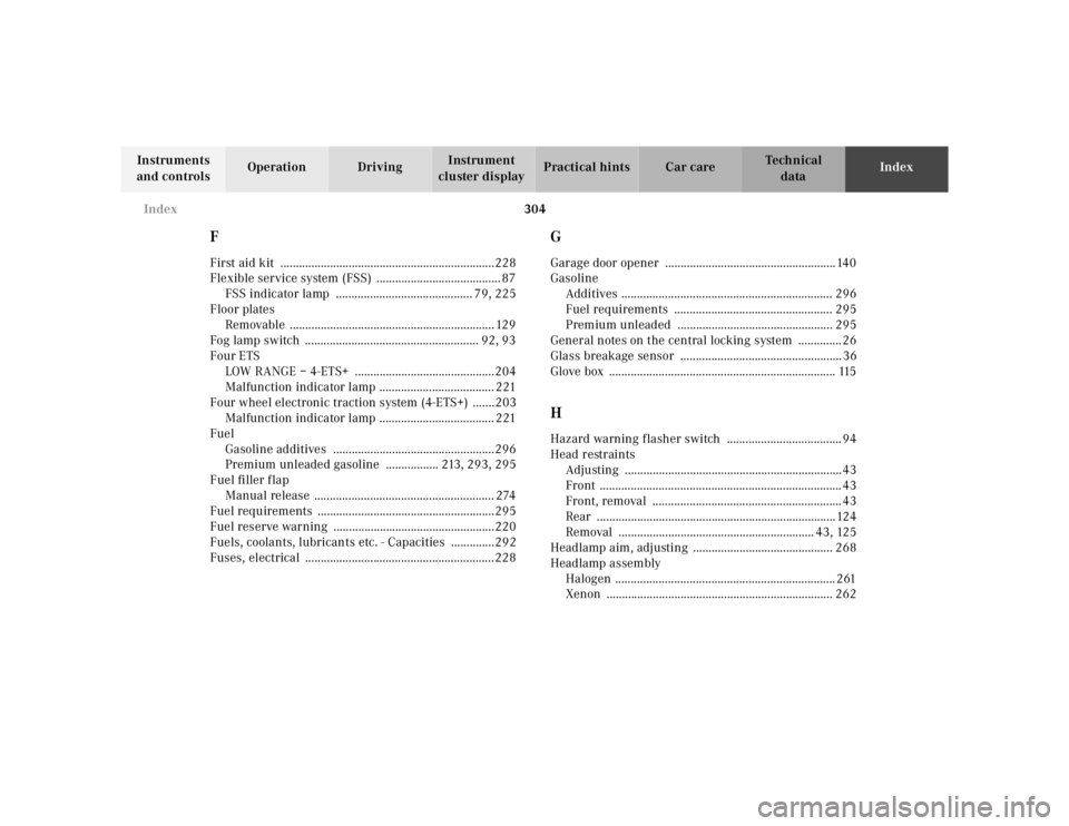
Fuses, electrical .............................................................228
GGarage door opener .......................................................140
Gasoline
Additives .................................................................... 296
Fuel requirements ................................................... 295
Premium unleaded .................................................. 295
General notes on the central locking system .............. 26
Glass breakage sensor .................................................... 36
Glove box ......................................................................... 115HHazard warning flasher switch ..................................... 94
Head restraints
Adjusting ......................................................................43
Front .............................................................................. 43
Front, removal ............................................................. 43
Rear .............................................................................124
Removal ............................................................... 43, 125
Headlamp aim, adjusting ............................................. 268
Headlamp assembly
Halogen ....................................................................... 261
Xenon ......................................................................... 262
Page 379 of 4133
module.
2. To install air bag module, reverse removal procedur e. Activate air bag system. Perform system operation
check to ensure system is functioning properly. See SYSTEM OPERATION CHECK
.
Removal & Installation (SLK 320)
1. Before proceeding, See AIR BAG SAFETY PRECAUTIONS . Disable air bag system. See
DISABLING & ACTIVATI NG AIR BAG SYSTEM
. Remove ignition key. Remove top section of
instrument panel. Fold vapor barrier toward front to reveal 2 screws. Disconnect passenger-side air bag
module connector. Remove 4 screws and passenger-side air bag module.
2. To install air bag module, reverse removal procedur e. Activate air bag system. Perform system operation
check to ensure system is functioning properly. See SYSTEM OPERATION CHECK
.
DIAGNOSTICS
Before proceeding, see AIR BAG SAFETY PRECAUTIONS
. The SRS control module is capable of
diagnosing air bag system components and ETR components. If a fault is detected by the SRS control module
or system is malfunctioning, SRS warning light will do one or more of the following:
SRS warning light goes out after 2 minutes. System fault is noted, however occupant protection is not
affected. See RETRIEVING FAULT CODES
.
SRS warning light illuminates cont inuously. System is faulty which may result in a non deployment or
false deployment. See RETRIEVING FAULT CODES
.
SRS warning light blinks continuous ly. Control module has been replaced without setting control module
parameters.
RETRIEVING FAULT CODES
1. Check vehicle fuses. Replace any blown fuses as nece ssary. Ensure vehicle battery voltage is 11 volts or
more. Ensure SRS warning light functions. Turn i gnition off. Connect Hand-Held Tester (HHT) (965 589
00 01) to Data Link Connector (DLC).
2. DLC is located in right rear corner of engine comp artment. It may be necessary to use Adapter (965 589
00 40 or 965 589 00 50) to connect HHT to DLC. Afte r HHT displays module number and version, press
return key to start diagnosis. Us ing HHT, follow HHT prompts to re trieve SRS fault codes. For SRS
control modules beginning with number 000, fault c ode 1 is valid. For SRS control modules beginning
with number 001, fault code 2 is valid. See Fig. 6
.
3. HHT will display a 3 digit fault code, and may display additional graphic information. This additional
graphic information will help in diagnosis of fault code. See Fig. 5
. During diagnosis HHT will display 4
different graphic displays info rming technician if a test passes or fail s, or if seat belt buckle is latched or
NOTE: After component replacement, perf
orm a system operation check to ensure
proper system operation. S ee SYSTEM OPERATION CHECK
.
NOTE: Fault codes may only be retrieved us ing Hand-Held Tester (965 589 00 01) and
Adapter (965 589 00 40 or 965 589 00 50).
2001 Mercedes-Benz ML320
2000-01 ACCESSORIES/SAFETY EQUIPMENT Merc edes-Benz - Air Bag Restraint Systems
me
Saturday, October 02, 2010 3:44:45 PMPage 15 © 2006 Mitchell Repair Information Company, LLC.
Page 471 of 4133

4
Contents
Practical hintsFirst aid kit .....................................228
Fuses ................................................228
Electrical outlet ..............................230
Stowing things in the vehicle ......230
Hood ................................................. 231
Checking engine oil level .............233
Automatic transmission fluid level ...................................234
Engine oil consumption ................234
Coolant level ...................................234 Adding coolant ...........................235
Windshield washer/headlamp cleaning system .........................236
Windshield and
headlamp washer fluid
mixing ratio ................................237 Vehicle jack, wheel bolt
wrench and screwdriver ......... 237
Air pump ......................................... 239
Wheels ............................................ 240 Tire replacement ....................... 240
Rotating wheels ......................... 241
Spare wheel .................................... 242
Changing wheels ........................... 245
Tire inflation pressure ................. 250
Battery ............................................. 251
Jump starting ................................. 253
Towing the vehicle ........................ 255 Transmission selector lever,
manually unlocking .................. 259
Stranded vehicle ............................ 259 Exterior lamps ................................260
Headlamp assembly ................... 261
Taillamp assemblies ..................265
Adjusting headlamp aim ...............268
Remote control battery replacement .................270
Synchronizing
remote control ............................ 271
Emergency operation of sliding/pop-up roof ...................272
Emergency operation of Skyview Top ...............................273
Manual release for fuel filler flap ............................. 274
Replacing wiper blades .................275
Roof rack ......................................... 276