Page 1714 of 4133
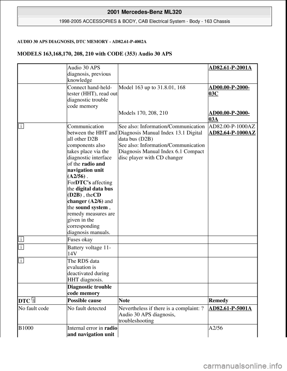
AUDIO 30 APS DIAGNOSIS, DTC MEMORY - AD82.61-P-4002A
MODELS 163,168,170, 208, 210 with CODE (353) Audio 30 APS
Audio 30 APS
diagnosis, previous
knowledge AD82.61-P-2001A
Connect hand-held-
tester (HHT), read out
diagnostic trouble
code memoryModel 163 up to 31.8.01, 168AD00.00-P-2000-
03C
Models 170, 208, 210AD00.00-P-2000-
03A
Communication
between the HHT and
all other D2B
components also
takes place via the
diagnostic interface
of the radio and
navigation unit
(A2/56) .
ForDTC's affecting
the digital data bus
(D2B) , theCD
changer (A2/6) and
the sound system ,
remedy measures are
given in the
corresponding
diagnosis manuals.
See also: Information/Communication
Diagnosis Manual Index 13.1 Digital
data bus (D2B)
See also: Information/Communication
Diagnosis Manual Index 6.1 Compact
disc player with CD changerAD82.00-P-1000AZ
AD82.64
-P-1000AZ
Fuses okay
Battery voltage 11-
14V
The RDS data
evaluation is
deactivated during
HHT diagnosis.
Diagnostic trouble
code memory
DTC Possible cause Note Remedy
No fault codeNo fault detectedNevertheless if there is a complaint: ?
Audio 30 APS diagnosis,
troubleshootingAD82.61-P-5001A
B1000Internal error in radio
and navigation unit A2/56
2001 Mercedes-Benz ML320
1998-2005 ACCESSORIES & BODY, CAB Electrical System - Body - 163 Chassis
me
Saturday, October 02, 2010 3:30:08 PMPage 219 © 2006 Mitchell Repair Information Company, LLC.
Page 1733 of 4133
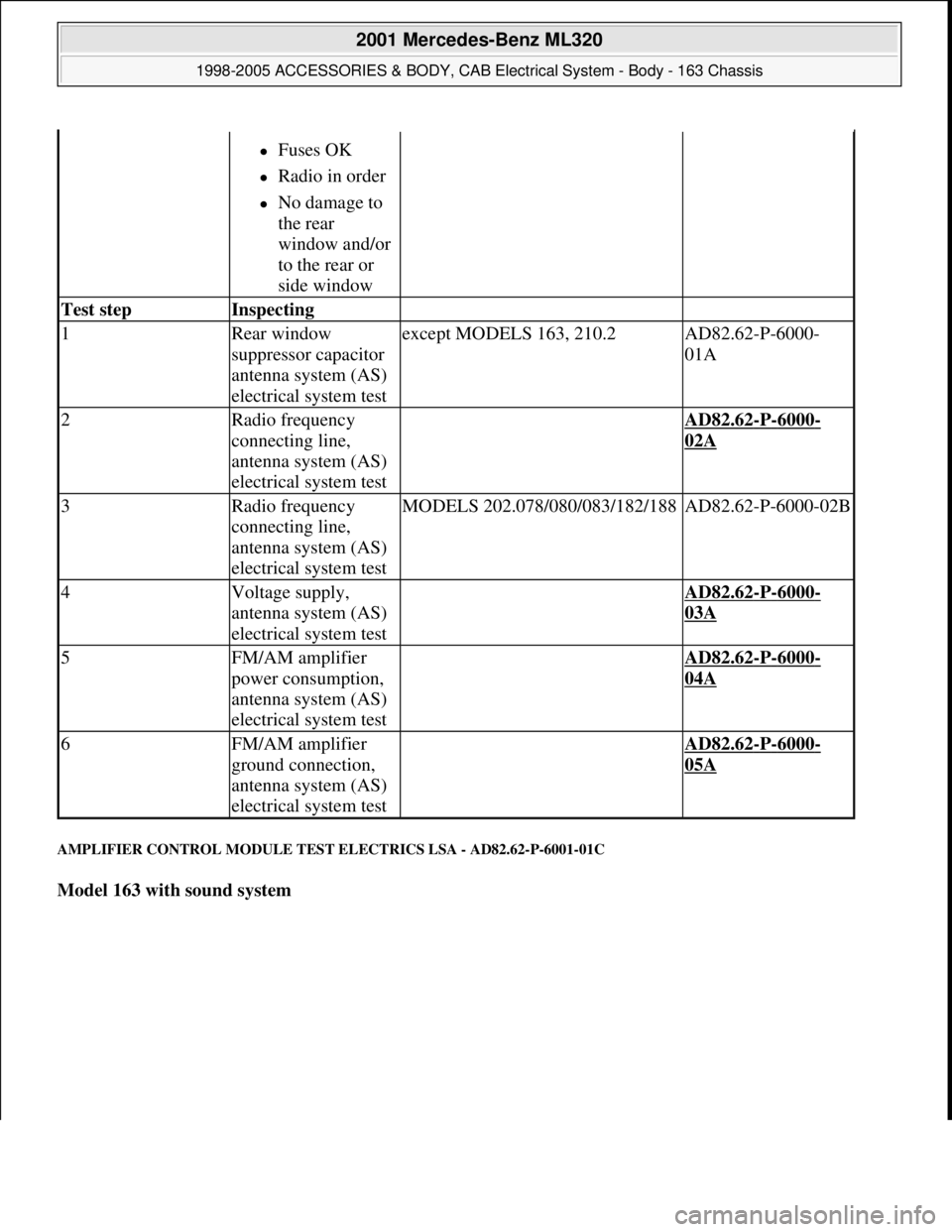
AMPLIFIER CONTROL MODULE TEST ELECTRICS LSA - AD82.62-P-6001-01C
Model 163 with sound system
Fuses OK
Radio in order
No damage to
the rear
window and/or
to the rear or
side window
Test step Inspecting
1Rear window
suppressor capacitor
antenna system (AS)
electrical system testexcept MODELS 163, 210.2AD82.62-P-6000-
01A
2Radio frequency
connecting line,
antenna system (AS)
electrical system test AD82.62-P-6000-
02A
3Radio frequency
connecting line,
antenna system (AS)
electrical system testMODELS 202.078/080/083/182/188AD82.62-P-6000-02B
4Voltage supply,
antenna system (AS)
electrical system test AD82.62-P-6000-
03A
5FM/AM amplifier
power consumption,
antenna system (AS)
electrical system test AD82.62-P-6000-
04A
6FM/AM amplifier
ground connection,
antenna system (AS)
electrical system test AD82.62-P-6000-
05A
2001 Mercedes-Benz ML320
1998-2005 ACCESSORIES & BODY, CAB Electrical System - Body - 163 Chassis
me
Saturday, October 02, 2010 3:30:08 PMPage 238 © 2006 Mitchell Repair Information Company, LLC.
Page 1738 of 4133
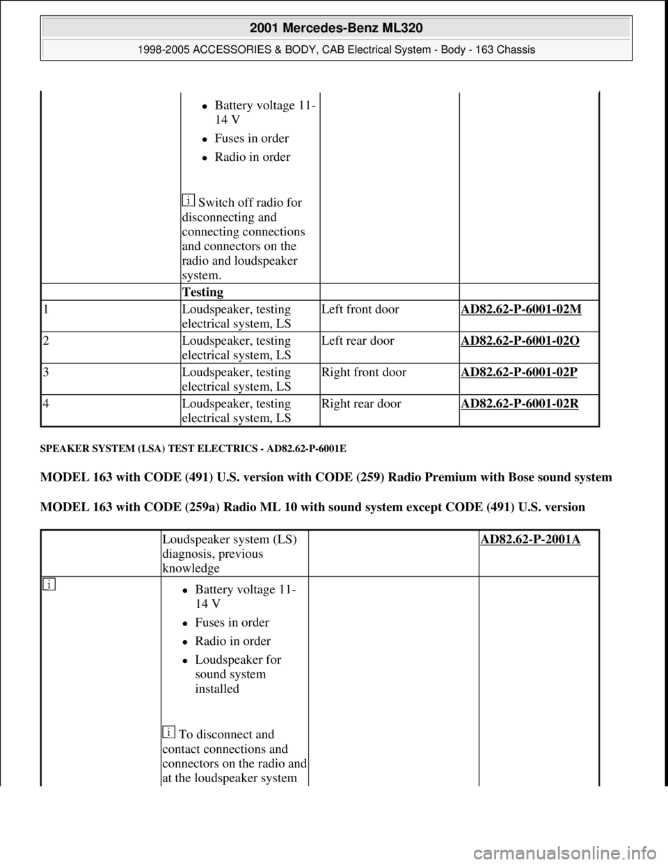
SPEAKER SYSTEM (LSA) TEST ELECTRICS - AD82.62-P-6001E
MODEL 163 with CODE (491) U.S. version with CODE (259) Radio Premium with Bose sound system
MODEL 163 with CODE (259a) Radio ML 10 with sound system except CODE (491) U.S. version
Battery voltage 11-
14 V
Fuses in order
Radio in order
Switch off radio for
disconnecting and
connecting connections
and connectors on the
radio and loudspeaker
system.
Testing
1Loudspeaker, testing
electrical system, LSLeft front doorAD82.62-P-6001-02M
2Loudspeaker, testing
electrical system, LSLeft rear doorAD82.62-P-6001-02O
3Loudspeaker, testing
electrical system, LSRight front doorAD82.62-P-6001-02P
4Loudspeaker, testing
electrical system, LSRight rear doorAD82.62-P-6001-02R
Loudspeaker system (LS)
diagnosis, previous
knowledge AD82.62-P-2001A
Battery voltage 11-
14 V
Fuses in order
Radio in order
Loudspeaker for
sound system
installed
To disconnect and
contact connections and
connectors on the radio and
at the loudspeaker system
2001 Mercedes-Benz ML320
1998-2005 ACCESSORIES & BODY, CAB Electrical System - Body - 163 Chassis
me
Saturday, October 02, 2010 3:30:08 PMPage 243 © 2006 Mitchell Repair Information Company, LLC.
Page 1741 of 4133
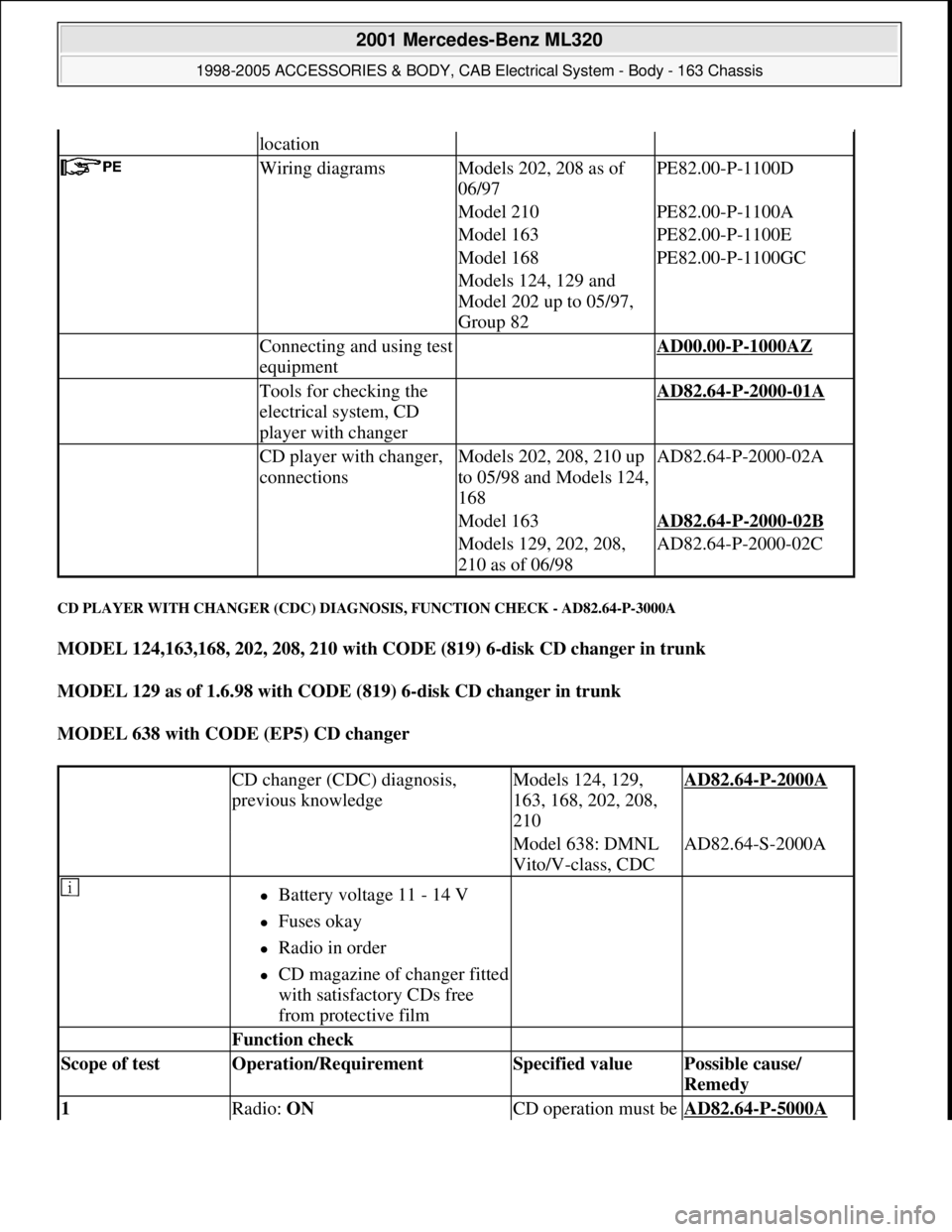
CD PLAYER WITH CHANGER (CDC) DIAGNOSIS, FUNCTION CHECK - AD82.64-P-3000A
MODEL 124,163,168, 202, 208, 210 with CODE (819) 6-disk CD changer in trunk
MODEL 129 as of 1.6.98 with CODE (819) 6-disk CD changer in trunk
MODEL 638 with CODE (EP5) CD changer
location
Wiring diagramsModels 202, 208 as of
06/97PE82.00-P-1100D
Model 210PE82.00-P-1100A
Model 163PE82.00-P-1100E
Model 168PE82.00-P-1100GC
Models 124, 129 and
Model 202 up to 05/97,
Group 82
Connecting and using test
equipment AD00.00-P-1000AZ
Tools for checking the
electrical system, CD
player with changer AD82.64-P-2000-01A
CD player with changer,
connectionsModels 202, 208, 210 up
to 05/98 and Models 124,
168AD82.64-P-2000-02A
Model 163AD82.64-P-2000-02B
Models 129, 202, 208,
210 as of 06/98AD82.64-P-2000-02C
CD changer (CDC) diagnosis,
previous knowledgeModels 124, 129,
163, 168, 202, 208,
210AD82.64-P-2000A
Model 638: DMNL
Vito/V-class, CDCAD82.64-S-2000A
Battery voltage 11 - 14 V
Fuses okay
Radio in order
CD magazine of changer fitted
with satisfactory CDs free
from protective film
Function check
Scope of test Operation/Requirement Specified value Possible cause/
Remedy
1 Radio: ON CD operation must be AD82.64-P-5000A
2001 Mercedes-Benz ML320
1998-2005 ACCESSORIES & BODY, CAB Electrical System - Body - 163 Chassis
me
Saturday, October 02, 2010 3:30:08 PMPage 246 © 2006 Mitchell Repair Information Company, LLC.
Page 1744 of 4133
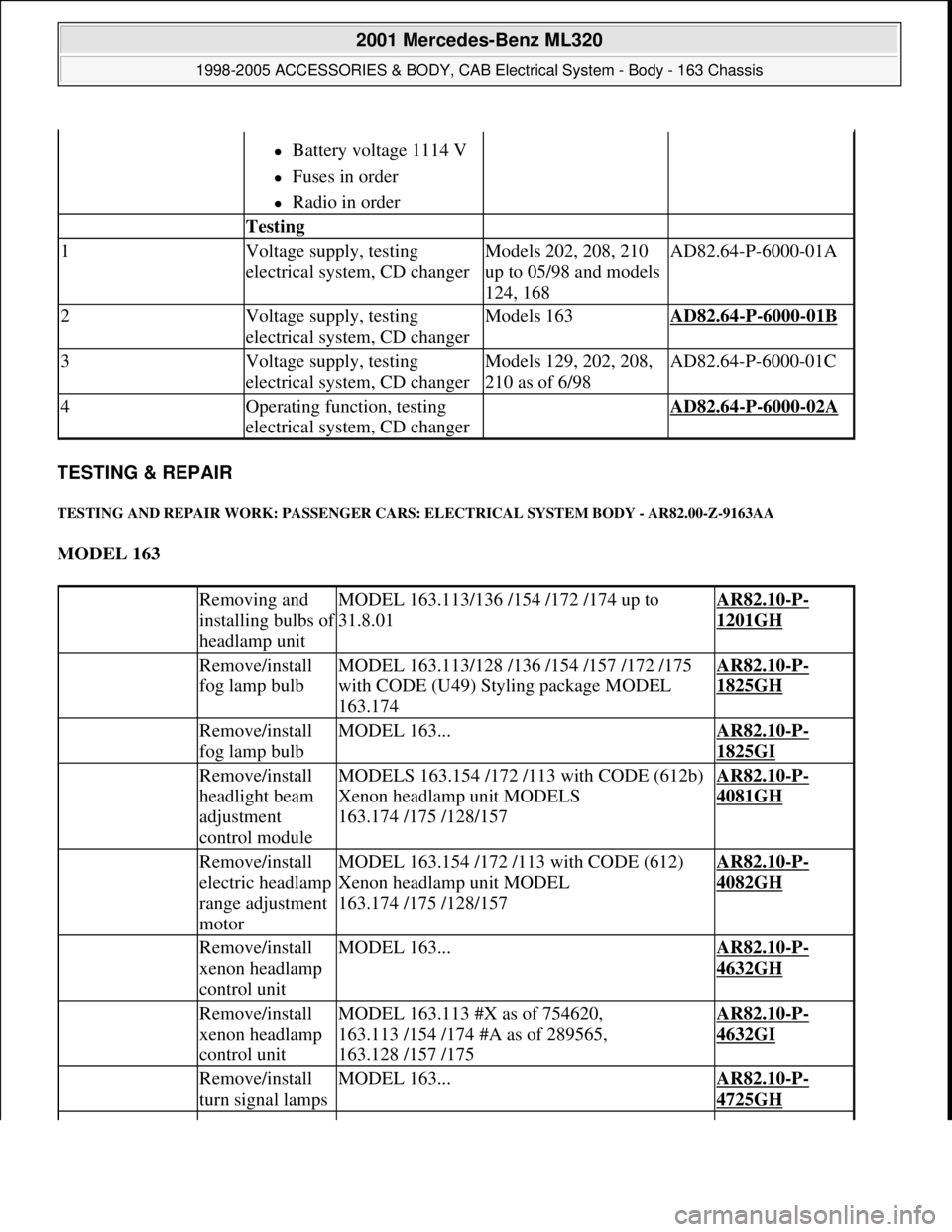
TESTING & REPAIR
TESTING AND REPAIR WORK: PASSENGER CARS: ELECTRICAL SYSTEM BODY - AR82.00-Z-9163AA
MODEL 163
Battery voltage 1114 V
Fuses in order
Radio in order
Testing
1Voltage supply, testing
electrical system, CD changerModels 202, 208, 210
up to 05/98 and models
124, 168AD82.64-P-6000-01A
2Voltage supply, testing
electrical system, CD changerModels 163AD82.64-P-6000-01B
3Voltage supply, testing
electrical system, CD changerModels 129, 202, 208,
210 as of 6/98AD82.64-P-6000-01C
4Operating function, testing
electrical system, CD changer AD82.64-P-6000-02A
Removing and
installing bulbs o
f
headlamp unit
MODEL 163.113/136 /154 /172 /174 up to
31.8.01AR82.10-P-
1201GH
Remove/install
fog lamp bulbMODEL 163.113/128 /136 /154 /157 /172 /175
with CODE (U49) Styling package MODEL
163.174AR82.10-P-
1825GH
Remove/install
fog lamp bulbMODEL 163...AR82.10-P-
1825GI
Remove/install
headlight beam
adjustment
control moduleMODELS 163.154 /172 /113 with CODE (612b)
Xenon headlamp unit MODELS
163.174 /175 /128/157AR82.10-P-
4081GH
Remove/install
electric headlamp
range adjustment
motorMODEL 163.154 /172 /113 with CODE (612)
Xenon headlamp unit MODEL
163.174 /175 /128/157AR82.10-P-
4082GH
Remove/install
xenon headlamp
control unitMODEL 163...AR82.10-P-
4632GH
Remove/install
xenon headlamp
control unitMODEL 163.113 #X as of 754620,
163.113 /154 /174 #A as of 289565,
163.128 /157 /175AR82.10-P-
4632GI
Remove/install
turn signal lampsMODEL 163...AR82.10-P-
4725GH
2001 Mercedes-Benz ML320
1998-2005 ACCESSORIES & BODY, CAB Electrical System - Body - 163 Chassis
me
Saturday, October 02, 2010 3:30:08 PMPage 249 © 2006 Mitchell Repair Information Company, LLC.
Page 2037 of 4133
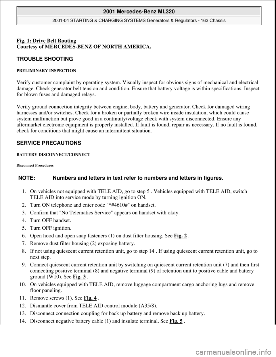
Fig. 1: Drive Belt Routing
Courtesy of MERCEDES-BENZ OF NORTH AMERICA.
TROUBLE SHOOTING
PRELIMINARY INSPECTION
Verify customer complaint by operating system. Visually inspect for obvious signs of mechanical and electrical
damage. Check generator belt tension and condition. Ensure that battery voltage is within specifications. Inspect
for blown fuses and damaged relays.
Verify ground connection integrity between engine, body, battery and generator. Check for damaged wiring
harnesses and/or switches. Check for a broken or partially broken wire inside insulation, which could cause
system malfunction but prove good in a continuity/voltage check with system disconnected. Ensure any
aftermarket electronic equipment is properly installed. If fault is found, repair as necessary. If no fault is found,
check for conditions that might cause an intermittent situation.
SERVICE PRECAUTIONS
BATTERY DISCONNECT/CONNECT
Disconnect Procedures
1. On vehicles not equipped with TELE AID, go to step 5 . Vehicles equipped with TELE AID, switch
TELE AID into service mode by turning ignition ON.
2. Turn ON telephone and enter code "*#4610#" on handset.
3. Confirm that "No Telematics Service" appears on handset with okay.
4. Turn OFF handset.
5. Turn OFF ignition.
6. Open hood and open snap fasteners (1) on dust filter housing. See Fig. 2
.
7. Remove dust filter housing (2) exposing battery.
8. If not using quiescent current retention unit, go to step 14 . If using quiescent current retention unit, go to
next step.
9. Connect quiescent current retention unit by switching on quiescent current retention unit (7) and then first
connecting positive terminal (8) and negative terminal (9) of retention unit to positive cable and battery
ground (W10). See Fig. 3
.
10. On vehicles equipped with TELE AID, remove luggage compartment cargo anchoring lugs and remove
floor paneling.
11. Remove screws (1). See Fig. 4
.
12. Dismantle cover from TELE AID control module (A35/8).
13. Disconnect connection coupling for back up battery and remove back up battery.
14. Disconnect ne
gative battery cable (1) and insulate terminal. See Fig. 5. NOTE: Numbers and letters in text refer to numbers and letters in figures.
2001 Mercedes-Benz ML320
2001-04 STARTING & CHARGING SYSTEMS Generators & Regulators - 163 Chassis
me
Saturday, October 02, 2010 3:20:31 PMPage 3 © 2006 Mitchell Repair Information Company, LLC.
Page 2615 of 4133
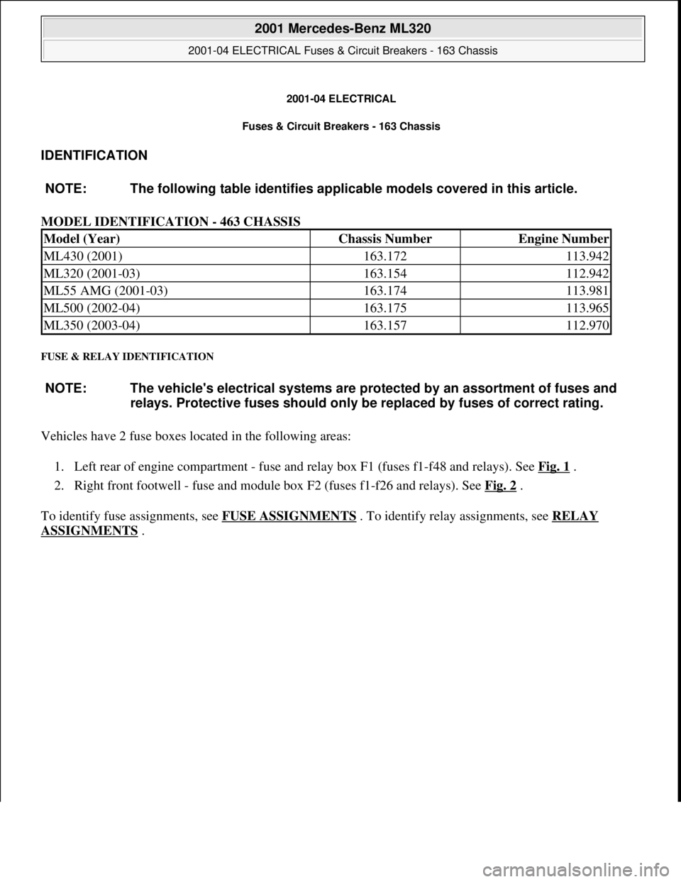
2001-04 ELECTRICAL
Fuses & Circuit Breakers - 163 Chassis
IDENTIFICATION
MODEL IDENTIFICATION - 463 CHASSIS
FUSE & RELAY IDENTIFICATION
Vehicles have 2 fuse boxes located in the following areas:
1. Left rear of engine compartment - fuse and relay box F1 (fuses f1-f48 and relays). See Fig. 1
.
2. Right front footwell - fuse and module box F2 (fuses f1-f26 and relays). See Fig. 2
.
To identify fuse assignments, see FUSE ASSIGNMENTS
. To identify relay assignments, see RELAY
ASSIGNMENTS . NOTE: The following table identifies applicable models covered in this article.
Model (Year)Chassis NumberEngine Number
ML430 (2001)163.172113.942
ML320 (2001-03)163.154112.942
ML55 AMG (2001-03)163.174113.981
ML500 (2002-04)163.175113.965
ML350 (2003-04)163.157112.970
NOTE: The vehicle's electrical systems are protected by an assortment of fuses and
relays. Protective fuses should only be replaced by fuses of correct rating.
2001 Mercedes-Benz ML320
2001-04 ELECTRICAL Fuses & Circuit Breakers - 163 Chassis
2001 Mercedes-Benz ML320
2001-04 ELECTRICAL Fuses & Circuit Breakers - 163 Chassis
me
Saturday, October 02, 2010 3:22:06 PMPage 1 © 2006 Mitchell Repair Information Company, LLC.
me
Saturday, October 02, 2010 3:22:09 PMPage 1 © 2006 Mitchell Repair Information Company, LLC.
Page 2616 of 4133
Fig. 1: Locating Fuse & Relay Box F1
Courtesy of MERCEDES-BENZ OF NORTH AMERICA.
2001 Mercedes-Benz ML320
2001-04 ELECTRICAL Fuses & Circuit Breakers - 163 Chassis
me
Saturday, October 02, 2010 3:22:06 PMPage 2 © 2006 Mitchell Repair Information Company, LLC.