1997 MERCEDES-BENZ ML320 horn
[x] Cancel search: hornPage 20 of 4133
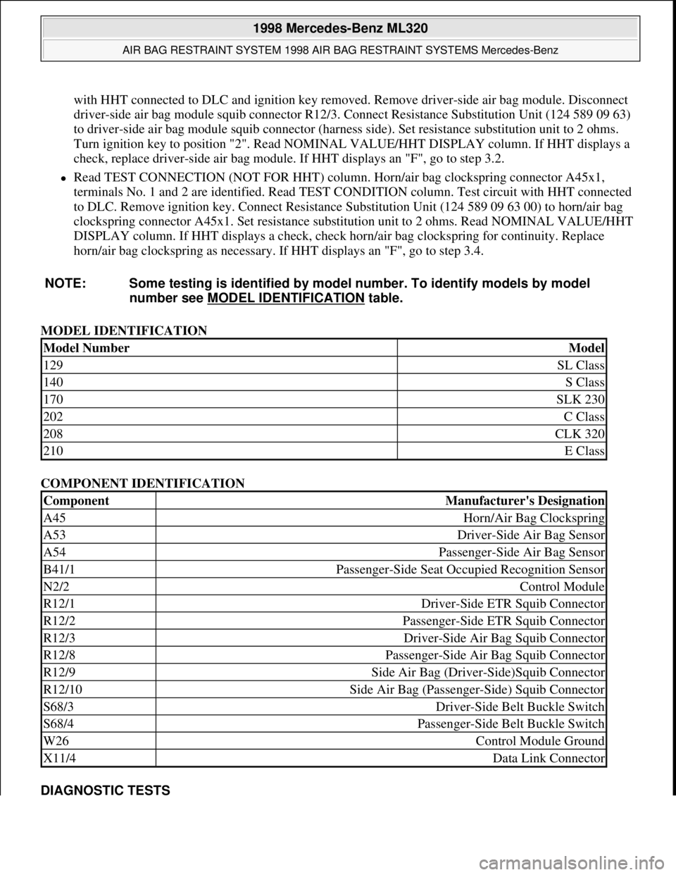
with HHT connected to DLC and ignition key removed. Remove driver-side air bag module. Disconnect
driver-side air bag module squib connector R12/3. Connect Resistance Substitution Unit (124 589 09 63)
to driver-side air bag module squib connector (harness side). Set resistance substitution unit to 2 ohms.
Turn ignition key to position "2". Read NOMINAL VALUE/HHT DISPLAY column. If HHT displays a
check, replace driver-side air bag module. If HHT displays an "F", go to step 3.2.
Read TEST CONNECTION (NOT FOR HHT) column. Horn/air bag clockspring connector A45x1,
terminals No. 1 and 2 are identified. Read TEST CONDITION column. Test circuit with HHT connected
to DLC. Remove ignition key. Connect Resistance Substitution Unit (124 589 09 63 00) to horn/air bag
clockspring connector A45x1. Set resistance substitution unit to 2 ohms. Read NOMINAL VALUE/HHT
DISPLAY column. If HHT displays a check, check horn/air bag clockspring for continuity. Replace
horn/air bag clockspring as necessary. If HHT displays an "F", go to step 3.4.
MODEL IDENTIFICATION
COMPONENT IDENTIFICATION
DIAGNOSTIC TESTS NOTE: Some testing is identified by model number. To identify models by model
number see MODEL IDENTIFICATION
table.
Model NumberModel
129SL Class
140S Class
170SLK 230
202C Class
208CLK 320
210E Class
ComponentManufacturer's Designation
A45Horn/Air Bag Clockspring
A53Driver-Side Air Bag Sensor
A54Passenger-Side Air Bag Sensor
B41/1Passenger-Side Seat Occupied Recognition Sensor
N2/2Control Module
R12/1Driver-Side ETR Squib Connector
R12/2Passenger-Side ETR Squib Connector
R12/3Driver-Side Air Bag Squib Connector
R12/8Passenger-Side Air Bag Squib Connector
R12/9Side Air Bag (Driver-Side)Squib Connector
R12/10Side Air Bag (Passenger-Side) Squib Connector
S68/3Driver-Side Belt Buckle Switch
S68/4Passenger-Side Belt Buckle Switch
W26Control Module Ground
X11/4Data Link Connector
1998 Mercedes-Benz ML320
AIR BAG RESTRAINT SYSTEM 1998 AIR BAG RESTRAINT SYSTEMS Mercedes-Benz
me
Saturday, October 02, 2010 3:33:14 PMPage 20 © 2006 Mitchell Repair Information Company, LLC.
Page 69 of 4133
19 Instruments and controls
Te ch n ica l
data Instruments
and controlsOperation DrivingInstrument
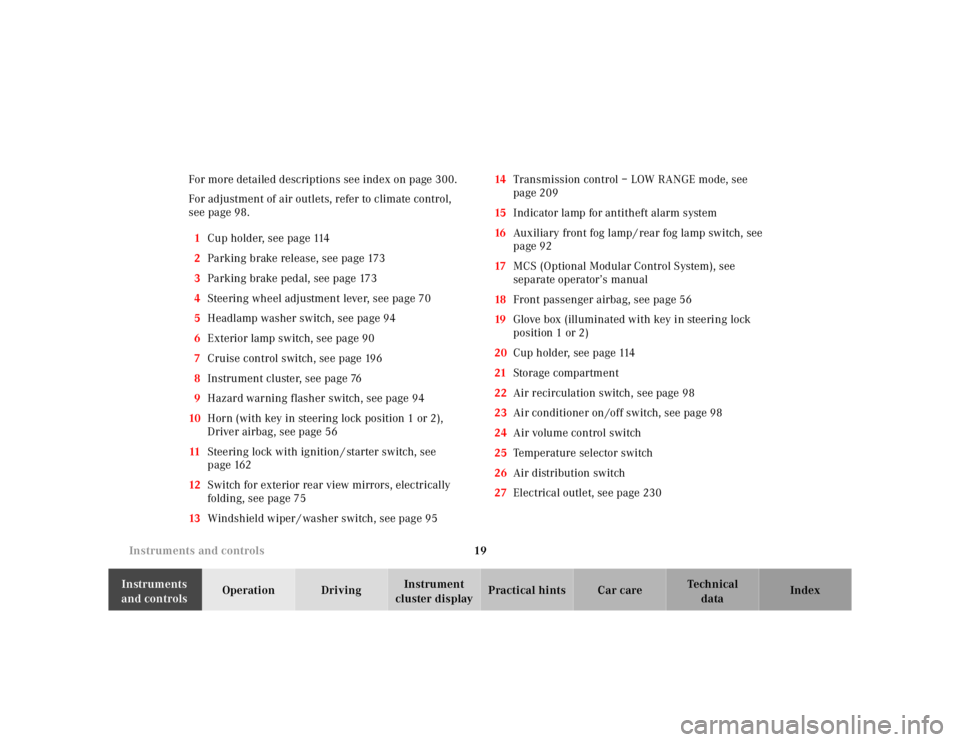
cluster displayPractical hints Car care Index For more detailed descriptions see index on page 300.
For adjustment of air outlets, refer to climate control,
see page 98.
1Cup holder, see page 114
2Parking brake release, see page 173
3Parking brake pedal, see page 173
4Steering wheel adjustment lever, see page 70
5Headlamp washer switch, see page 94
6Exterior lamp switch, see page 90
7Cruise control switch, see page 196
8Instrument cluster, see page 76
9Hazard warning flasher switch, see page 94
10Horn (with key in steering lock position 1 or 2),
Driver airbag, see page 56
11Steering lock with ignition / starter switch, see
page 162
12Switch for exterior rear view mirrors, electrically
folding, see page 75
13Windshield wiper / washer switch, see page 9514Transmission control – LOW RANGE mode, see
page 209
15Indicator lamp for antitheft alarm system
16Auxiliary front fog lamp / rear fog lamp switch, see
page 92
17MCS (Optional Modular Control System), see
separate operator’s manual
18Front passenger airbag, see page 56
19Glove box (illuminated with key in steering lock
position 1 or 2)
20Cup holder, see page 114
21Storage compartment
22Air recirculation switch, see page 98
23Air conditioner on /off switch, see page 98
24Air volume control switch
25Temperature selector switch
26Air distribution switch
27Electrical outlet, see page 230
Page 85 of 4133
35 Antitheft alarm system
Te ch n ica l
data Instruments
and controlsOperationDrivingInstrument
cluster displayPractical hints Car care Index Antitheft alarm system
The indicator lamp is located in the center console.
The antitheft alarm is automatically armed or disarmed
with the remote control by locking or unlocking the
vehicle.
The antitheft alarm is armed within approximately
15 seconds after locking the vehicle with the remote
control.
A blinking lamp in the center console indicates that the
alarm is armed.
Notes:
Use of the key in the front door locks does not arm or
disarm the antitheft alarm system.
The alarm sounds when unlocking the driver’s door
with the mechanical key. Cancel alarm by turning key in
steering lock to position 1, or with the remote control by
pressing buttonŒ.
If the vehicle battery voltage falls below 10 volts, the
alarm is automatically canceled and the antitheft alarm
system is disarmed. When the voltage is above this
value again, the antitheft alarm system is armed again.Operation:
Once the alarm system has been armed, the turn signal
lamps will flash rapidly (approximately 3 minutes) and
the horn will sound intermittently (approximately
30 seconds) when someone:
•opens a door,
•opens the liftgate,
•opens the hood,
•breaks a window,
•attempts to raise the vehicle.
The alarm will stay on even if the activating element (a
door, for example) is immediately closed.
If the alarm stays on for more than 20 seconds, an
emergency call is initiated automatically. See Tele Aid
on page 148.
Note:
The alarm system will cycle three times when triggered.
The interior lights are automatically switched on when
the alarm comes on and go out when canceling the
alarm.
Page 86 of 4133
36 Tow-away protection
Te ch n ica l
data Instruments
and controlsOperationDrivingInstrument
cluster displayPractical hints Car care Index
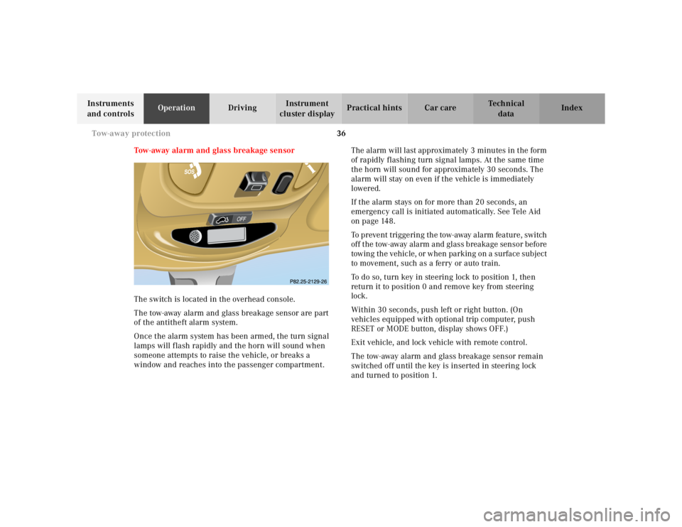
Tow-away alarm and glass breakage sensor
The switch is located in the overhead console.
The tow-away alarm and glass breakage sensor are part
of the antitheft alarm system.
Once the alarm system has been armed, the turn signal
lamps will flash rapidly and the horn will sound when
someone attempts to raise the vehicle, or breaks a
window and reaches into the passenger compartment.The alarm will last approximately 3 minutes in the form
of rapidly flashing turn signal lamps. At the same time
the horn will sound for approximately 30 seconds. The
alarm will stay on even if the vehicle is immediately
lowered.
If the alarm stays on for more than 20 seconds, an
emergency call is initiated automatically. See Tele Aid
on page 148.
To prevent triggering the tow-away alarm feature, switch
off the tow-away alarm and glass breakage sensor before
towing the vehicle, or when parking on a surface subject
to movement, such as a ferry or auto train.
To do so, turn key in steering lock to position 1, then
return it to position 0 and remove key from steering
lock.
Within 30 seconds, push left or right button. (On
vehicles equipped with optional trip computer, push
RESET or MODE button, display shows OFF.)
Exit vehicle, and lock vehicle with remote control.
The tow-away alarm and glass breakage sensor remain
switched off until the key is inserted in steering lock
and turned to position 1.
Page 385 of 4133
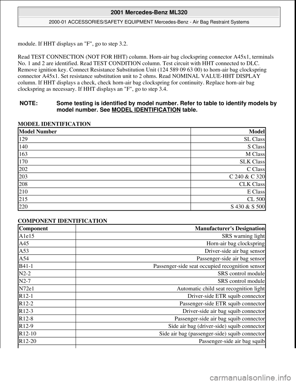
module. If HHT displays an "F", go to step 3.2.
Read TEST CONNECTION (NOT FOR HHT) column. Horn -air bag clockspring connector A45x1, terminals
No. 1 and 2 are identified. Read TEST CONDITION column. Test circuit with HHT connected to DLC.
Remove ignition key. Connect Resist ance Substitution Unit (124 589 09 63 00) to horn-air bag clockspring
connector A45x1. Set resistance s ubstitution unit to 2 ohms. Read NOMINAL VALUE-HHT DISPLAY
column. If HHT displays a check, check horn-air ba g clockspring for continuity. Replace horn-air bag
clockspring as necessary. If HHT displays an "F", go to step 3.4.
MODEL IDENTIFICATION
COMPONENT IDENTIFICATION
NOTE: Some testing is identified
by model number. Refer to table to identify models by
model number. See MO DEL IDENTIFICATION
table.
Model NumberModel
129SL Class
140S Class
163M Class
170SLK Class
202C Class
203C 240 & C 320
208CLK Class
210E Class
215CL 500
220S 430 & S 500
ComponentManufacturer's Designation
A1e15SRS warning light
A45Horn-air bag clockspring
A53Driver-side air bag sensor
A54Passenger-side air bag sensor
B41-1Passenger-side seat occupied recognition sensor
N2-2SRS control module
N2-7SRS control module
N72e1Automatic child seat recognition light
R12-1Driver-side ETR squib connector
R12-2Passenger-side ETR squib connector
R12-3Driver-side air bag squib connector
R12-8Passenger-side air bag squib connector
R12-9Side air bag (driver-side) squib connector
R12-10Side air bag (passenge r-side) squib connector
R12-20Passenger-side air bag squib
2001 Mercedes-Benz ML320
2000-01 ACCESSORIES/SAFETY EQUIPMENT Merc edes-Benz - Air Bag Restraint Systems
me
Saturday, October 02, 2010 3:44:46 PMPage 21 © 2006 Mitchell Repair Information Company, LLC.
Page 486 of 4133
19
Instruments and controls
Te ch n ica l
data
Instruments
and controls Operation Driving
Instrument
cluster display Practical hints Car care Index
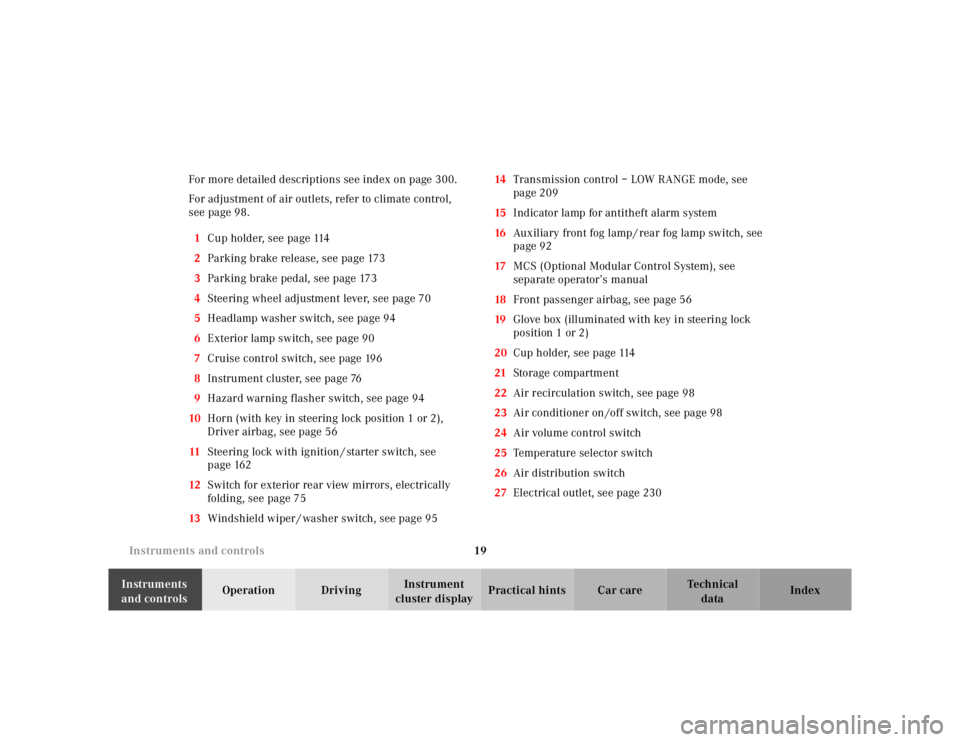
For more detailed descriptions see index on page 300.
For adjustment of air outlets, refer to climate control,
see page 98.
1 Cup holder, see page 114
2 Parking brake release, see page 173
3 Parking brake pedal, see page 173
4 Steering wheel adjustment lever, see page 70
5 Headlamp washer switch, see page 94
6 Exterior lamp switch, see page 90
7 Cruise control switch, see page 196
8 Instrument cluster, see page 76
9 Hazard warning flasher switch, see page 94
10 Horn (with key in steering lock position 1 or 2),
Driver airbag, see page 56
11 Steering lock with ignition / starter switch, see
page 162
12 Switch for exterior rear view mirrors, electrically
folding, see page 75
13 Windshield wiper / washer switch, see page 95 14
Transmission control – LOW RANGE mode, see
page 209
15 Indicator lamp for antitheft alarm system
16 Auxiliary front fog lamp / rear fog lamp switch, see
page 92
17 MCS (Optional Modular Control System), see
separate operator’s manual
18 Front passenger airbag, see page 56
19 Glove box (illuminated with key in steering lock
position 1 or 2)
20 Cup holder, see page 114
21 Storage compartment
22 Air recirculation switch, see page 98
23 Air conditioner on /off switch, see page 98
24 Air volume control switch
25 Temperature selector switch
26 Air distribution switch
27 Electrical outlet, see page 230
Page 502 of 4133
35
Antitheft alarm system
Te ch n ica l
data
Instruments
and controls Operation
Driving Instrument
cluster display Practical hints Car care Index
Antitheft alarm system
The indicator lamp is located in the center console.
The antitheft alarm is automatically armed or disarmed
with the remote control by locking or unlocking the
vehicle.
The antitheft alarm is armed within approximately
15 seconds after locking the vehicle with the remote
control.
A blinking lamp in the center console indicates that the
alarm is armed.
Notes:
Use of the key in the front door locks does not arm or
disarm the antitheft alarm system.
The alarm sounds when unlocking the driver’s door
with the mechanical key. Cancel alarm by turning key in
steering lock to position 1, or with the remote control by
pressing button Œ.
If the vehicle battery voltage falls below 10 volts, the
alarm is automatically canceled and the antitheft alarm
system is disarmed. When the voltage is above this
value again, the antitheft alarm system is armed again. Operation:
Once the alarm system has been armed, the turn signal
lamps will flash rapidly (approximately 3 minutes) and
the horn will sound intermittently (approximately
30 seconds) when someone:
• opens a door,
• opens the liftgate,
• opens the hood,
• breaks a window,
• attempts to raise the vehicle.
The alarm will stay on even if the activating element (a
door, for example) is immediately closed.
If the alarm stays on for more than 20 seconds, an
emergency call is initiated automatically. See Tele Aid
on page 148.
Note:
The alarm system will cycle three times when triggered.
The interior lights are automatically switched on when
the alarm comes on and go out when canceling the
alarm.
Page 503 of 4133
36
Tow-away protection
Te ch n ica l
data
Instruments
and controls Operation
Driving Instrument
cluster display Practical hints Car care Index
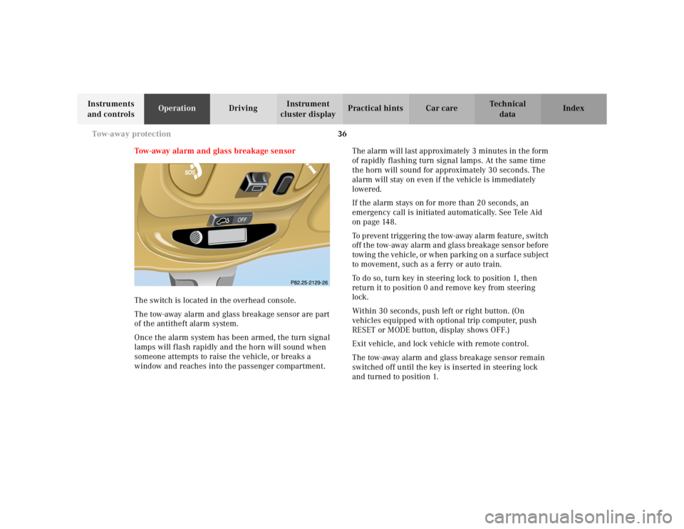
Tow-away alarm and glass breakage sensor
The switch is located in the overhead console.
The tow-away alarm and glass breakage sensor are part
of the antitheft alarm system.
Once the alarm system has been armed, the turn signal
lamps will flash rapidly and the horn will sound when
someone attempts to raise the vehicle, or breaks a
window and reaches into the passenger compartment. The alarm will last approximately 3 minutes in the form
of rapidly flashing turn signal lamps. At the same time
the horn will sound for approximately 30 seconds. The
alarm will stay on even if the vehicle is immediately
lowered.
If the alarm stays on for more than 20 seconds, an
emergency call is initiated automatically. See Tele Aid
on page 148.
To prevent triggering the tow-away alarm feature, switch
off the tow-away alarm and glass breakage sensor before
towing the vehicle, or when parking on a surface subject
to movement, such as a ferry or auto train.
To do so, turn key in steering lock to position 1, then
return it to position 0 and remove key from steering
lock.
Within 30 seconds, push left or right button. (On
vehicles equipped with optional trip computer, push
RESET or MODE button, display shows OFF.)
Exit vehicle, and lock vehicle with remote control.
The tow-away alarm and glass breakage sensor remain
switched off until the key is inserted in steering lock
and turned to position 1.