1997 MERCEDES-BENZ ML320 air condition
[x] Cancel search: air conditionPage 19 of 4133
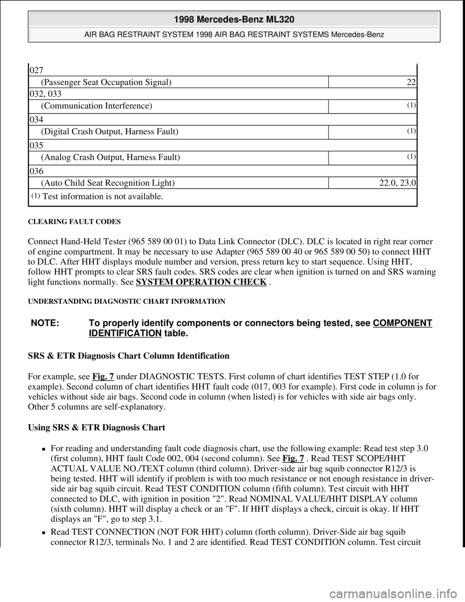
CLEARING FAULT CODES
Connect Hand-Held Tester (965 589 00 01) to Data Link Connector (DLC). DLC is located in right rear corner
of engine compartment. It may be necessary to use Adapter (965 589 00 40 or 965 589 00 50) to connect HHT
to DLC. After HHT displays module number and version, press return key to start sequence. Using HHT,
follow HHT prompts to clear SRS fault codes. SRS codes are clear when ignition is turned on and SRS warning
light functions normally. See SYSTEM OPERATION CHECK
.
UNDERSTANDING DIAGNOSTIC CHART INFORMATION
SRS & ETR Diagnosis Chart Column Identification
For example, see Fig. 7
under DIAGNOSTIC TESTS. First column of chart identifies TEST STEP (1.0 for
example). Second column of chart identifies HHT fault code (017, 003 for example). First code in column is for
vehicles without side air bags. Second code in column (when listed) is for vehicles with side air bags only.
Other 5 columns are self-explanatory.
Using SRS & ETR Diagnosis Chart
For reading and understanding fault code diagnosis chart, use the following example: Read test step 3.0
(first column), HHT fault Code 002, 004 (second column). See Fig. 7
. Read TEST SCOPE/HHT
ACTUAL VALUE NO./TEXT column (third column). Driver-side air bag squib connector R12/3 is
being tested. HHT will identify if problem is with too much resistance or not enough resistance in driver-
side air bag squib circuit. Read TEST CONDITION column (fifth column). Test circuit with HHT
connected to DLC, with ignition in position "2". Read NOMINAL VALUE/HHT DISPLAY column
(sixth column). HHT will display a check or an "F". If HHT displays a check, circuit is okay. If HHT
displays an "F", go to step 3.1.
Read TEST CONNECTION (NOT FOR HHT) column (forth column). Driver-Side air bag squib
connector R12/3, terminals No. 1 and 2 are identified. Read TEST CONDITION column. Test circuit
027
(Passenger Seat Occupation Signal)22
032, 033
(Communication Interference)(1)
034
(Digital Crash Output, Harness Fault)(1)
035
(Analog Crash Output, Harness Fault)(1)
036
(Auto Child Seat Recognition Light)22.0, 23.0
(1)Test information is not available.
NOTE: To properly identify components or connectors being tested, see COMPONENT
IDENTIFICATION table.
1998 Mercedes-Benz ML320
AIR BAG RESTRAINT SYSTEM 1998 AIR BAG RESTRAINT SYSTEMS Mercedes-Benz
me
Saturday, October 02, 2010 3:33:14 PMPage 19 © 2006 Mitchell Repair Information Company, LLC.
Page 20 of 4133
with HHT connected to DLC and ignition key removed. Remove driver-side air bag module. Disconnect
driver-side air bag module squib connector R12/3. Connect Resistance Substitution Unit (124 589 09 63)
to driver-side air bag module squib connector (harness side). Set resistance substitution unit to 2 ohms.
Turn ignition key to position "2". Read NOMINAL VALUE/HHT DISPLAY column. If HHT displays a
check, replace driver-side air bag module. If HHT displays an "F", go to step 3.2.
Read TEST CONNECTION (NOT FOR HHT) column. Horn/air bag clockspring connector A45x1,
terminals No. 1 and 2 are identified. Read TEST CONDITION column. Test circuit with HHT connected
to DLC. Remove ignition key. Connect Resistance Substitution Unit (124 589 09 63 00) to horn/air bag
clockspring connector A45x1. Set resistance substitution unit to 2 ohms. Read NOMINAL VALUE/HHT
DISPLAY column. If HHT displays a check, check horn/air bag clockspring for continuity. Replace
horn/air bag clockspring as necessary. If HHT displays an "F", go to step 3.4.
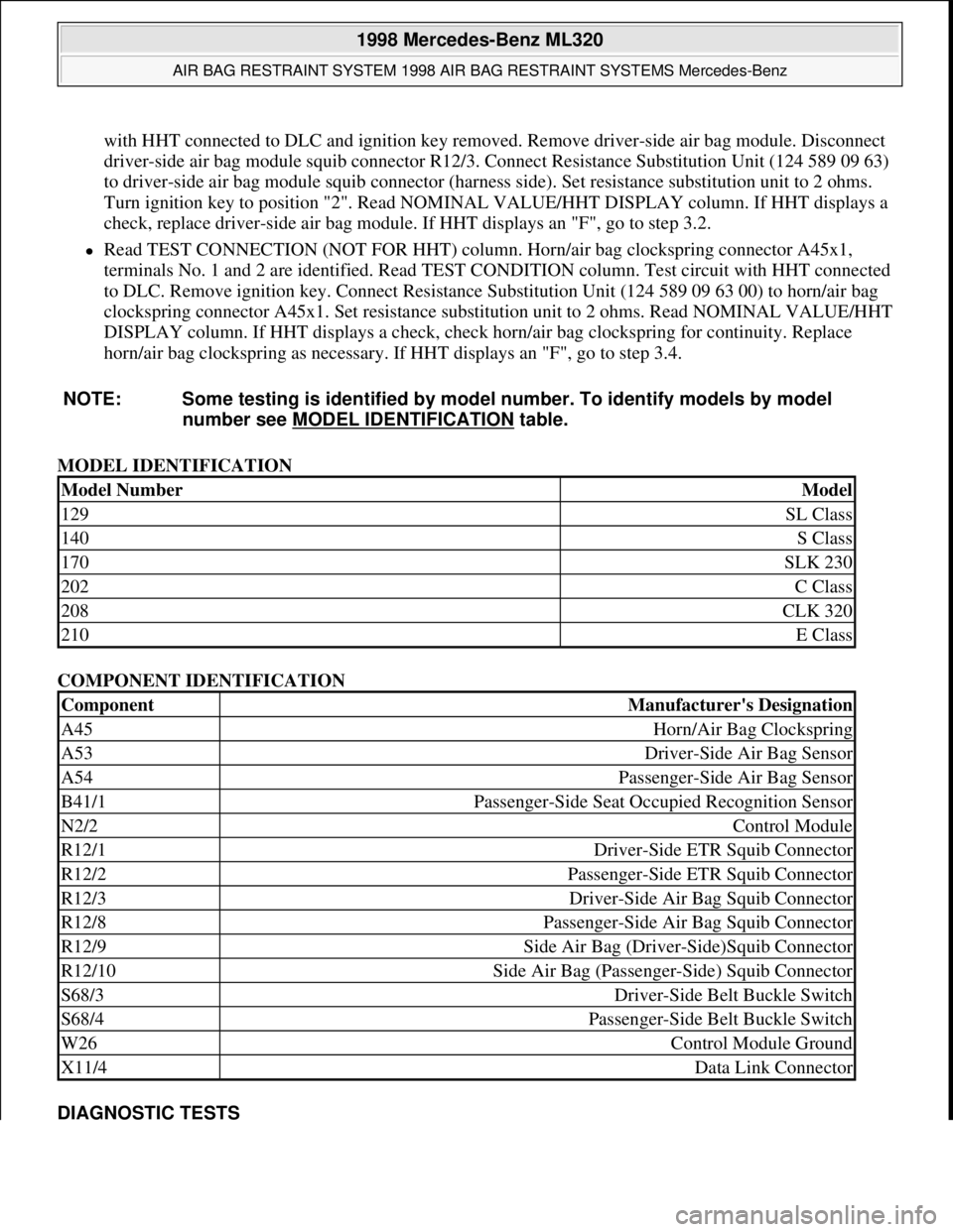
MODEL IDENTIFICATION
COMPONENT IDENTIFICATION
DIAGNOSTIC TESTS NOTE: Some testing is identified by model number. To identify models by model
number see MODEL IDENTIFICATION
table.
Model NumberModel
129SL Class
140S Class
170SLK 230
202C Class
208CLK 320
210E Class
ComponentManufacturer's Designation
A45Horn/Air Bag Clockspring
A53Driver-Side Air Bag Sensor
A54Passenger-Side Air Bag Sensor
B41/1Passenger-Side Seat Occupied Recognition Sensor
N2/2Control Module
R12/1Driver-Side ETR Squib Connector
R12/2Passenger-Side ETR Squib Connector
R12/3Driver-Side Air Bag Squib Connector
R12/8Passenger-Side Air Bag Squib Connector
R12/9Side Air Bag (Driver-Side)Squib Connector
R12/10Side Air Bag (Passenger-Side) Squib Connector
S68/3Driver-Side Belt Buckle Switch
S68/4Passenger-Side Belt Buckle Switch
W26Control Module Ground
X11/4Data Link Connector
1998 Mercedes-Benz ML320
AIR BAG RESTRAINT SYSTEM 1998 AIR BAG RESTRAINT SYSTEMS Mercedes-Benz
me
Saturday, October 02, 2010 3:33:14 PMPage 20 © 2006 Mitchell Repair Information Company, LLC.
Page 52 of 4133

2 Contents
Fog lamp switch
(except Canada) ........................... 92
Fog lamp switch
(Canada only) .............................. 93
Hazard warning flasher
switch ............................................ 94
Headlamp cleaning system ............ 94
Windshield wiper/washer
switch ............................................ 95
Rear window wiper/washer ........... 96
Climate control ................................. 98
Basic setting – Heater ............... 100
Basic setting –
Air conditioner ........................... 100
Special setting ............................ 101
Dust filter .................................... 102
Air recirculation ......................... 102
Rear window defroster .............. 103
Power windows ............................... 104
Rear quarter windows ................... 106
Sliding/pop-up roof ....................... 107
Skyview Top .................................... 109
Interior lighting ..............................110
Sun visors ........................................113Illuminated vanity mirrors ........... 113
Interior ............................................. 114
Storage compartments,
armrest and cup holder ............ 114
Glove box ...................................... 115
Armrest in rear bench seat ........... 117
Ashtrays ........................................... 118
Lighter .............................................. 119
Split rear seat bench ..................... 120
Easy entry/exit feature ............. 123
Rear seat head restraints ......... 124
Third row seats .............................. 126
Removable cargo floor plates ...... 129
Enlarged cargo area .......................131
Cargo tie-down rings .....................132
Hooks ...............................................133
Partition net ....................................133
Loading instructions ......................136
Cargo area cover blind ..................137
Telephone, general .........................139
Cellular telephone ..........................139
Garage door opener ....................... 140
DrivingControl and operation of
radio transmitters ..................... 146
The first 1 000 miles
(1 500 km) ................................. 147
Maintenance ................................... 147
Tele Aid ........................................... 148
Catalytic converter ........................ 160
Emission control ............................ 161
Steering lock ................................... 162
Starting and turning off
the engine .................................. 164
Automatic transmission ............... 165
Parking brake ................................. 173
Driving instructions ...................... 174
Drive sensibly – save fuel ......... 174
Drinking and driving ................. 174
Pedals ........................................... 174
Power assistance ........................ 175
Brakes .......................................... 175
Driving off ................................... 176
Parking ........................................ 176
Tires ............................................. 177
Page 55 of 4133

5 Contents
Vehicle careCleaning and care
of the vehicle .............................278
Power washer ..............................279
Tar stains .....................................279
Paintwork, painted body
components .................................279
Engine cleaning ..........................280
Vehicle washing .........................280
Ornamental moldings ................280
Headlamps, taillamps,
turn signal lenses ......................280
Window cleaning ........................ 281
Wiper blades ............................... 281
Light alloy wheels ...................... 281
Instrument cluster ..................... 281
Steering wheel and
gear selector lever ...................... 281Cup holder .................................. 282
Seat belts ..................................... 282
Headliner .................................... 282
Upholstery .................................. 282
Hard plastic trim items ............. 282
Plastic and rubber parts ........... 282
Technical dataSpare parts service ....................... 284
Warranty coverage ........................ 284
Identification labels ...................... 285
Layout of poly-V-belt drive ........... 286
Technical data ................................ 287
Fuels, coolants, lubricants
etc. – capacities ........................ 292
Engine oils ...................................... 294
Engine oil additives ...................... 294
Air conditioner refrigerant .......... 294Brake fluid ......................................294
Premium unleaded gasoline ........295
Fuel requirements .........................295
Gasoline additives .........................296
Coolants ...........................................296
Consumer information ..................298
IndexIndex ................................................300
Page 69 of 4133
19 Instruments and controls
Te ch n ica l
data Instruments
and controlsOperation DrivingInstrument
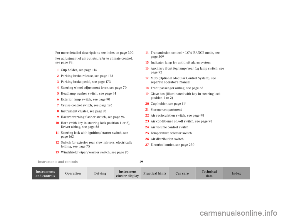
cluster displayPractical hints Car care Index For more detailed descriptions see index on page 300.
For adjustment of air outlets, refer to climate control,
see page 98.
1Cup holder, see page 114
2Parking brake release, see page 173
3Parking brake pedal, see page 173
4Steering wheel adjustment lever, see page 70
5Headlamp washer switch, see page 94
6Exterior lamp switch, see page 90
7Cruise control switch, see page 196
8Instrument cluster, see page 76
9Hazard warning flasher switch, see page 94
10Horn (with key in steering lock position 1 or 2),
Driver airbag, see page 56
11Steering lock with ignition / starter switch, see
page 162
12Switch for exterior rear view mirrors, electrically
folding, see page 75
13Windshield wiper / washer switch, see page 9514Transmission control – LOW RANGE mode, see
page 209
15Indicator lamp for antitheft alarm system
16Auxiliary front fog lamp / rear fog lamp switch, see
page 92
17MCS (Optional Modular Control System), see
separate operator’s manual
18Front passenger airbag, see page 56
19Glove box (illuminated with key in steering lock
position 1 or 2)
20Cup holder, see page 114
21Storage compartment
22Air recirculation switch, see page 98
23Air conditioner on /off switch, see page 98
24Air volume control switch
25Temperature selector switch
26Air distribution switch
27Electrical outlet, see page 230
Page 73 of 4133
23 Contents - Operation
Te ch n ica l
data Instruments
and controlsOperationDrivingInstrument
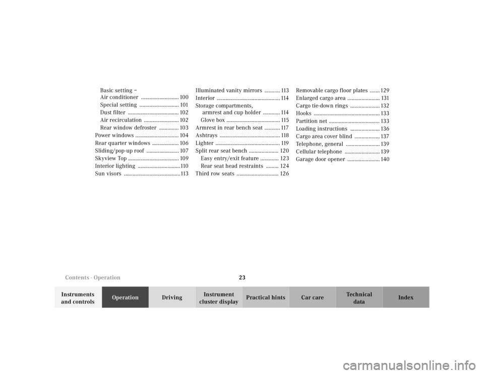
cluster displayPractical hints Car care Index Basic setting –
Air conditioner ........................... 100
Special setting ............................ 101
Dust filter .................................... 102
Air recirculation ......................... 102
Rear window defroster .............. 103
Power windows ............................... 104
Rear quarter windows ................... 106
Sliding/pop-up roof ....................... 107
Skyview Top .................................... 109
Interior lighting ..............................110
Sun visors ........................................113Illuminated vanity mirrors ........... 113
Interior ............................................. 114
Storage compartments,
armrest and cup holder ............ 114
Glove box ...................................... 115
Armrest in rear bench seat ........... 117
Ashtrays ........................................... 118
Lighter .............................................. 119
Split rear seat bench ..................... 120
Easy entry/exit feature ............. 123
Rear seat head restraints ......... 124
Third row seats .............................. 126Removable cargo floor plates ....... 129
Enlarged cargo area ....................... 131
Cargo tie-down rings ..................... 132
Hooks ............................................... 133
Partition net .................................... 133
Loading instructions ..................... 136
Cargo area cover blind .................. 137
Telephone, general ........................ 139
Cellular telephone ......................... 139
Garage door opener ....................... 140
Page 128 of 4133
78 Instrument cluster
Te ch n ica l
data Instruments
and controlsOperationDrivingInstrument
cluster displayPractical hints Car care Index
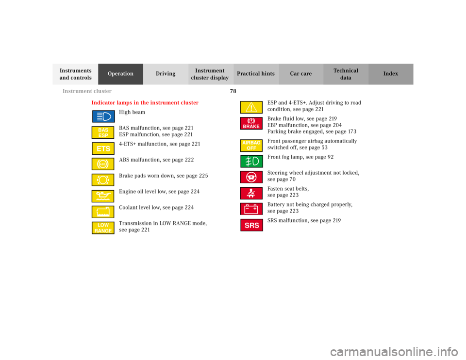
Indicator lamps in the instrument cluster
High beam
BAS malfunction, see page 221
ESP malfunction, see page 221
4-ETS+ malfunction, see page 221
ABS malfunction, see page 222
Brake pads worn down, see page 225
Engine oil level low, see page 224
Coolant level low, see page 224
Transmission in LOW RANGE mode,
see page 221ESP and 4-ETS+. Adjust driving to road
condition, see page 221
Brake fluid low, see page 219
EBP malfunction, see page 204
Parking brake engaged, see page 173
Front passenger airbag automatically
switched off, see page 53
Front fog lamp, see page 92
Steering wheel adjustment not locked,
see page 70
Fasten seat belts,
see page 223
Battery not being charged properly,
see page 223
SRS malfunction, see page 219
BAS
ESPABSLOW
RANGE
BRAKESRS
Page 149 of 4133
99 Climate control
Te ch n ica l
data Instruments
and controlsOperationDrivingInstrument
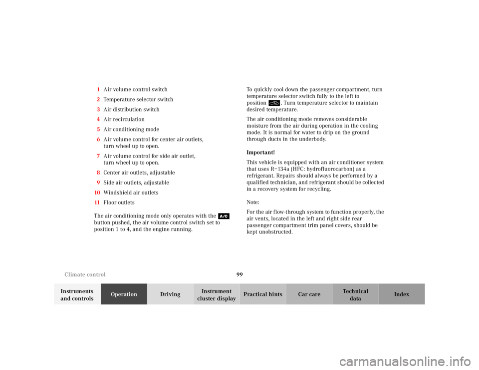
cluster displayPractical hints Car care Index 1Air volume control switch
2Temperature selector switch
3Air distribution switch
4Air recirculation
5Air conditioning mode
6Air volume control for center air outlets,
turn wheel up to open.
7Air volume control for side air outlet,
turn wheel up to open.
8Center air outlets, adjustable
9Side air outlets, adjustable
10Windshield air outlets
11Floor outlets
The air conditioning mode only operates with the œ
button pushed, the air volume control switch set to
position 1 to 4, and the engine running.To quickly cool down the passenger compartment, turn
temperature selector switch fully to the left to
positionO. Turn temperature selector to maintain
desired temperature.
The air conditioning mode removes considerable
moisture from the air during operation in the cooling
mode. It is normal for water to drip on the ground
through ducts in the underbody.
Important!
This vehicle is equipped with an air conditioner system
that uses R–134a (HFC: hydrof luorocarbon) as a
refrigerant. Repairs should always be performed by a
qualified technician, and refrigerant should be collected
in a recovery system for recycling.
Note:
For the air flow-through system to function properly, the
air vents, located in the left and right side rear
passenger compartment trim panel covers, should be
ke pt un obst ru cte d .