Page 640 of 1503
Description
Dual Mas s Flywhee l
The dua l mas s flywhee l i s designe d t o reduc e th e nois e an d vibration s produce d b y th e engine , clutch , an d transmissio n
durin g acceleratio n an d cruising .
Th e flywhee l assembl y i s actuall y tw o flywheel s i n one , whic h raise s th e inerti a mas s o n bot h th e engin e an d transmis -
sion . Th e inne r an d oute r flywheel s ar e connecte d b y torsio n springs . Thi s combinatio n effectivel y damper s change s i n
engin e spee d befor e the y ar e transmitte d to th e transmission .
Sinc e ther e ar e torsio n spring s betwee n th e flywheels , non e ar e use d in th e clutc h disc , whic h lessen s th e inerti a mas s o n
th e mainshaft . Thi s reductio n o f th e rotatin g inerti a mas s reduce s th e loa d o n th e synchr o rings , allowin g th e transmis -
sio n t o shif t smoother .
ProCarManuals.com
Page 660 of 1503

Transmission Assembl y
Removal
Make sur e lift s ar e place d properly , an d
hois t bracket s ar e attache d t o correc t position s (se e
sectio n 1 ).
1 . Chec k an d recor d th e rea r whee l alignmen t (se e
sectio n 18 ).
2 . Disconnec t th e batter y negativ e (- ) an d positiv e (+ )
cable s fro m th e battery .
3 . Drai n transmissio n oil . Reinstal l th e drai n plu g wit h
a ne w washer .
4 . Remov e th e stru t bar .
5 . Remov e th e ai r cleane r assembly . 6
. Remov e th e connector s fro m th e contro l box , an d
remov e th e contro l box . D o no t remov e th e vacuu m
tube s fro m th e contro l box .
7 . Remov e th e wir e harnes s holder , jumpe r connecto r
an d transmissio n groun d cable .
8 . Disconnec t th e back-u p ligh t switch , neutra l posi -
tio n switch , differentia l spee d sensor , revers e lock -
ou t solenoid , an d vehicl e spee d senso r (VSS ) con -
nectors .
9. Disconnec t th e starte r moto r cables , the n remov e
th e starte r motor .
10 . Remov e th e transmissio n mount .
11 . Remov e th e tw o transmissio n housin g bolts .
ProCarManuals.com
Page 662 of 1503

Transmission Assembl y
Removal (cont'd )
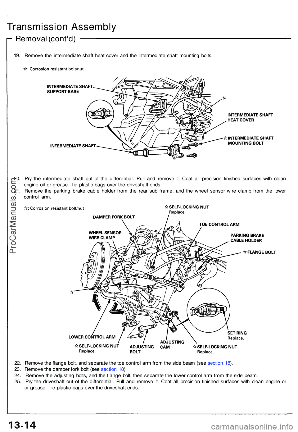
19. Remov e th e intermediat e shaf t hea t cove r an d th e intermediat e shaf t mountin g bolts .
20 . Pr y th e intermediat e shaf t ou t o f th e differential . Pul l an d remov e it . Coa t al l precisio n finishe d surface s wit h clea n
engin e oi l o r grease . Ti e plasti c bag s ove r th e driveshaf t ends .
21 . Remov e th e parkin g brak e cabl e holde r fro m th e rea r su b frame , an d th e whee l senso r wir e clam p fro m th e lowe r
contro l arm .
22 . Remov e th e flang e bolt , an d separat e th e to e contro l ar m fro m th e sid e bea m (se e sectio n 18 ).
23 . Remov e th e damper fork bol t (se e sectio n 18 ).
24 . Remov e th e adjustin g bolts , an d th e flang e bolt , the n separat e th e lowe r contro l ar m fro m th e sid e beam .
25 . Pr y th e driveshaf t ou t o f th e differential . Pul l an d remov e it . Coa t al l precisio n finishe d surfaces with clea n engin e oi l
o r grease . Ti e plasti c bag s ove r th e driveshaf t ends .
ProCarManuals.com
Page 663 of 1503

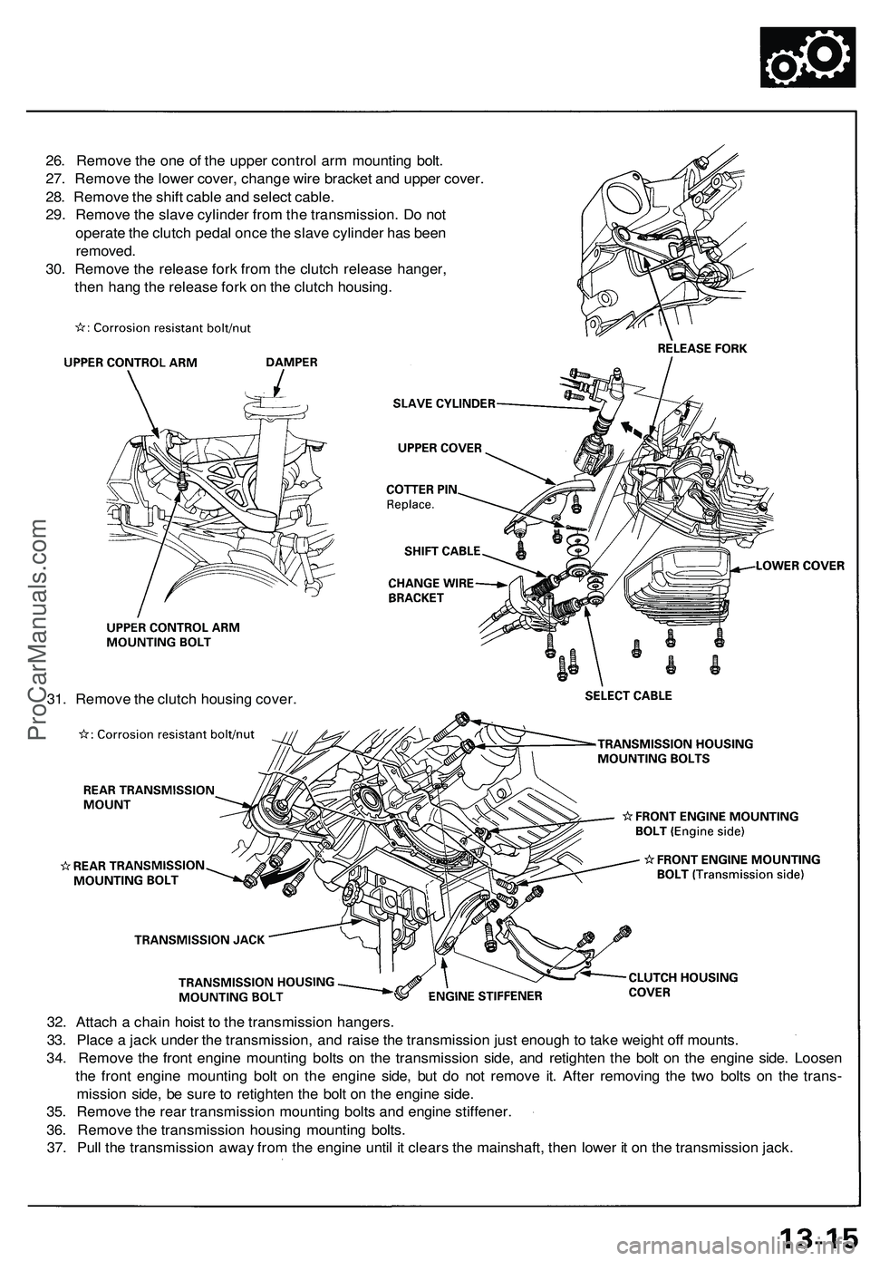
32. Attach a chain hoist to the transmission hangers.
33. Place a jack under the transmission, and raise the transmission just enough to take weight off mounts.
34. Remove the front engine mounting bolts on the transmission side, and retighten the bolt on the engine side. Loosen
the front engine mounting bolt on the engine side, but do not remove it. After removing the two bolts on the trans-
mission side, be sure to retighten the bolt on the engine side.
35. Remove the rear transmission mounting bolts and engine stiffener.
36. Remove the transmission housing mounting bolts.
37. Pull the transmission away from the engine until it clears the mainshaft, then lower it on the transmission jack.
26. Remove the one of the upper control arm mounting bolt.
27. Remove the lower cover, change wire bracket and upper cover.
28. Remove the shift cable and select cable.
29. Remove the slave cylinder from the transmission. Do not
operate the clutch pedal once the slave cylinder has been
removed.
30. Remove the release fork from the clutch release hanger,
then hang the release fork on the clutch housing.
31. Remove the clutch housing cover.ProCarManuals.com
Page 665 of 1503
BEARING OUTER RACE
75 mm THRUST SHIM
Selection.
CLAMP
BACK-UP LIGHT SWITCH
25 N-m (2.5 kgf-m, 18 Ibf-ft)
CLAMP
TRANSMISSION HANGER B
TRANSMISSION HANGER A
CLAMP
CLAMP
WASHER Replace.
OIL FILLER PLUG
44 N-m (4.5 kgf-m, 33 Ibf-ft)
42 x 63 x 12.5 mm OIL SEAL
Replace.
WASHER Replace.
DRAIN PLUG
39 N-m (4.0 kgf-m, 29 Ibf-ft)
36 mm SEALING BOLT
34 N-m (3.5 kgf-m, 25 Ibf-ft)
STRAINER COVER
O-RING Replace.
STRAINER SET SPRING
OIL PUMP STRAINER
14 mm SEALING BOLT
32 N-m (3.3 kgf-m, 24 Ibf-ft)
SPRING (L. 25 mm)
STEEL BALL (3/8 in)
REVERSE LOCKOUT SOLENOID
O-RING Replace.
SELECT LOCK PIN
SELECT LOCK RETURN SPRING
SELECT LOCK COLLAR
SPRING (L. 30 mm)
12 mm SEALING BOLT
22 N-m (2.2 kgf-m, 16 Ibf-ft)
STEEL BALL (5/16 in)
SHIFT LEVER ASSEMBLY
Removal, page 13-23
Installation, page 13-48
NEUTRAL POSITION SWITCH
25 N-m (2.5 kgf-m, 18 Ibf-ft)
TRANSMISSION HOUSING
OIL GUIDE PLATE
82 mm THRUST SHIM
Selection, page 13-46ProCarManuals.com
Page 666 of 1503
Transmission Housin g
Remova l
1. Plac e th e clutc h housin g o n tw o piece s o f woo d
thic k enoug h t o kee p th e mainshaf t fro m hittin g th e
workbench .
2 . Remov e th e bac k u p ligh t switch , neutra l positio n
switch , revers e lockou t solenoid , differentia l spee d
senso r an d vehicl e spee d senso r (VSS) .
3 . Remov e th e sealin g bolts , spring s an d stee l balls .
4 . Remov e th e transmissio n housin g attachin g bolt s i n
a crisscros s patter n in severa l steps .
5 . Remov e th e 3 6 m m sealin g bolt . 6
. Expan d th e sna p rin g o n th e countershaf t bal l bear -
ing , an d remov e i t fro m th e groov e usin g a pai r o f
sna p rin g plier .
7 . Separat e th e clutc h housin g fro m th e transmissio n
housing .
8 . Remov e th e thrus t shi m an d oi l guid e plat e fro m
th e transmissio n housing .
ProCarManuals.com
Page 675 of 1503
Shift Lever,
Select Lever
Removal
1. Remove the shift spring set plate and shift detent
spring from the transmission housing.
2. Remove the bolt and spring washer.
3. Pull out the shift lever, then remove the shift arm.ProCarManuals.com
Page 697 of 1503
Clearance Inspection
1. Check the clearance between the transmission mat-
ing surface of the clutch housing and the oil pump
gear.
3. Check the radial clearance on the pump rotor.
2. Check the axial clearance on the pump rotor.
Inner Rotor-to-Outer Rotor Radial clearance
Standard: 0.14 mm (0.006 in) max.
Service Limit: 0.2 mm (0.008 in)
4. Check the radial clearance between the clutch hous-
ing and the outer rotor.
Clutch Housing-to-Rotor Radial clearance
Standard: 0.1 - 0.2 mm
(0.004-0.008 in)
Service Limit: 0.22 mm (0.009 in)
Standard: 0.3 - 0.8 mm (0.012 - 0.031 in)
Service Limit: 0.9 mm (0.035 in)
Clutch Housing-to-Rotor Axial clearance
Standard: 0.03-0.1 mm
(0.001 - 0.004 in)
Service Limit: 0.15 mm (0.006 in)ProCarManuals.com