Page 374 of 1503

4-5
Y
Do the items in parts A, B, C, D, E, F, and G as required for the mileag\
e/time interval listed.
NOTE: According to state and federal regulations, failure to do the maintenanc\
e items marked with an asterisk (*) will not
void the customer ’s emissions warranties. However, Acura recommends that all maintenance s\
ervices be done at
the recommended interval to ensure long-term reliability.
*1: Refer to the 1997 NSX Service Manual, P/N 61SL006.
*2: Refer to the 1998 NSX Service Manual Supplement, P/N 61SL007.
*3: Refer to the 2001 NSX Service Manual Supplement, P/N 61SW000.
A
B Replace engine oil (see page
8-2)*
2, every 7,500 miles (12,000 km) or 1 year.
Engine oil capacity: without oil filter: 4.3 L (4.5 US qt).
Check tire inflation and condition at least once a month, every 7,500 mi\
les (12,000 km).
Replace engine oil filter (see page 8-5)*1, every 15,000 miles (24,000 km) or 1 year.
Engine oil capacity: with oil filter: 5.0 L (5.3 US qt).
Check front and rear brake wear (see page 19-4)*1, every 15,000 miles (24,000 km) or 1 year.
• Check pads and discs for wear (thickness), damage, and cracks.
• Check calipers for damage, leaks, and tightness of mounting bolts.
Check parking brake adjustment (see page 19-5)*1, every 15,000 miles (24,000 km) or 1 year.
Check the number of clicks (10 to 14) when the parking brake lever is pulled with 196 N (20 kgf,\
44 lbf) of force.
Inspect tie-rod ends, steering gearbox, and gearbox boots (see page 17-57)*1, every 15,000 miles (24,000 km) or 1 year.
• Check rack grease and steering linkage.
• Check boots for damage and leaking grease.
• Check fluid lines for damage and leaks.1
• Check bolts for tightness.
• Check condition of ball joint boots for deterioration and damage.
Inspect driveshaft boots (see page 16-3)*1, every 15,000 miles (24,000 km) or 1 year.
Check boots for cracks and boot bands for tightness.
Inspect brake hoses and lines including ABS (see page 19-27)*1, every 15,000 miles (24,000 km) or 1 year.
Check the master cylinder, proportioning control valve and ABS modulator\
for damage and leakage.
Inspect all fluid levels and condition of fluids, every 15,000 miles (2\
4,000 km) or 1 year.
• Manual transmission fluid (MTF) (see page 13-3)*
1.
• Automatic transmission fluid (ATF-Z1) (see page 14-105)*1.
• Engine coolant (see page 10-2)*1.
• Brake fluid (see page 19-84)*1.
• Windshield washer fluid.
Cooling system hoses and connections (see page 10-2)*1, every 15,000 miles (24,000 km) or 1 year.
• Check all hoses for damage, leaks and deterioration.
• Check for proper fan operation.
Inspect exhaust system (see page 9-6)*, *1, every 15,000 miles (24,000 km) or 1 year.
Check catalytic converter heat shield, exhaust pipe, and muffler for dam\
age, leaks, and tightness ( see page 9-14 ).
Inspect fuel lines and connections (see page 11-130)*, *1, every 15,000 miles (24,000 km) or 1 year.
Check for loose connections, cracks, and deterioration; retighten loose \
connections and replace damaged parts.
Part Maintenance Items
*05-NSX (61SW004)SEC04(01-10) 9/22/04 1:49 PM Page 4-5
Inspect suspension components (see page 18-14)* , every 15,000 miles (24,000 km) or 1 year.
ProCarManuals.com
Page 375 of 1503

4-6
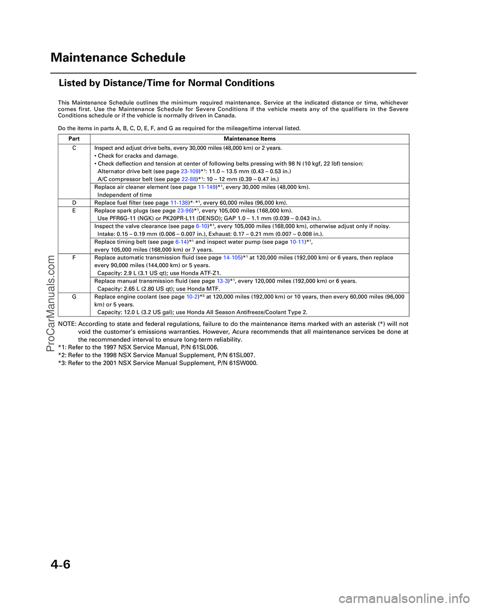
This Maintenance Schedule outlines the minimum required maintenance. Ser\
vice at the indicated distance or time, whichever
comes first. Use the Maintenance Schedule for Severe Conditions if the v\
ehicle meets any of the qualifiers in the Severe
Conditions schedule or if the vehicle is normally driven in Canada.
Do the items in parts A, B, C, D, E, F, and G as required for the mileag\
e/time interval listed.
NOTE: According to state and federal regulations, failure to do the maintenanc\
e items marked with an asterisk (*) will not
void the customer ’s emissions warranties. However, Acura recommends that all maintenance s\
ervices be done at
the recommended interval to ensure long-term reliability.
*1: Refer to the 1997 NSX Service Manual, P/N 61SL006.
*2: Refer to the 1998 NSX Service Manual Supplement, P/N 61SL007.
*3: Refer to the 2001 NSX Service Manual Supplement, P/N 61SW000.
C
D
E
F
G Inspect and adjust drive belts, every 30,000 miles (48,000 km) or 2 ye\
ars.
•
Check for cracks and damage.
• Check deflection and tension at center of following belts pressing with\
98 N (10 kgf, 22 lbf) tension:
Alternator drive belt (see page 23-109)*
1: 11.0 – 13.5 mm (0.43 – 0.53 in.)
A/C compressor belt (see page 22-88)*1: 10 – 12 mm (0.39 – 0.47 in.)
Replace air cleaner element (see page 11-149)*1, every 30,000 miles (48,000 km).
Independent of time
Replace fuel filter (see page 11-138)*, *1, every 60,000 miles (96,000 km).
Replace spark plugs (see page 23-96)*1, every 105,000 miles (168,000 km).
Use PFR6G-11 (NGK) or PK20PR-L11 (DENSO); GAP 1.0 – 1.1 mm (0.039 – 0.043 in.).
Inspect the valve clearance (see page 6-10)*1, every 105,000 miles (168,000 km), otherwise adjust only if noisy.
Intake: 0.15 – 0.19 mm (0.006 – 0.007 in.), Exhaust: 0.17 – 0.21 mm (0.007 – 0.008 in.).
Replace timing belt (see page 6-14)*1 and inspect water pump (see page 10-11)*1,
every 105,000 miles (168,000 km) or 7 years.
Replace automatic transmission fluid (see page 14-105)*1 at 120,000 miles (192,000 km) or 6 years, then replace
every 90,000 miles (144,000 km) or 5 years.
Capacity: 2.9 L (3.1 US qt); use Honda ATF-Z1.
Replace manual transmission fluid (see page 13-3)*1, every 120,000 miles (192,000 km) or 6 years.
Capacity: 2.65 L (2.80 US qt); use Honda MTF.
Replace engine coolant (see page 10-2 )*3 at 120,000 miles (192,000 km) or 10 years, then every 60,000 miles (9\
6,000
km) or 5 years. Capacity: 12.0 L (3.2 US gal); use Honda All Season Antifreeze/Coolant\
Type 2.
Part Maintenance Items
Maintenance Schedule
Listed by Distance/Time for Normal Conditions
*05-NSX (61SW004)SEC04(01-10) 9/22/04 1:49 PM Page 4-6
ProCarManuals.com
Page 376 of 1503
CANADA Model
Vehicle Identification Number
Transmission Number
Paint Code
Vehicle Identification Number
and Canadian Motor Vehicle
Safety Standard Certification
Paint Code
Engine NumberProCarManuals.com
Page 384 of 1503

Towing
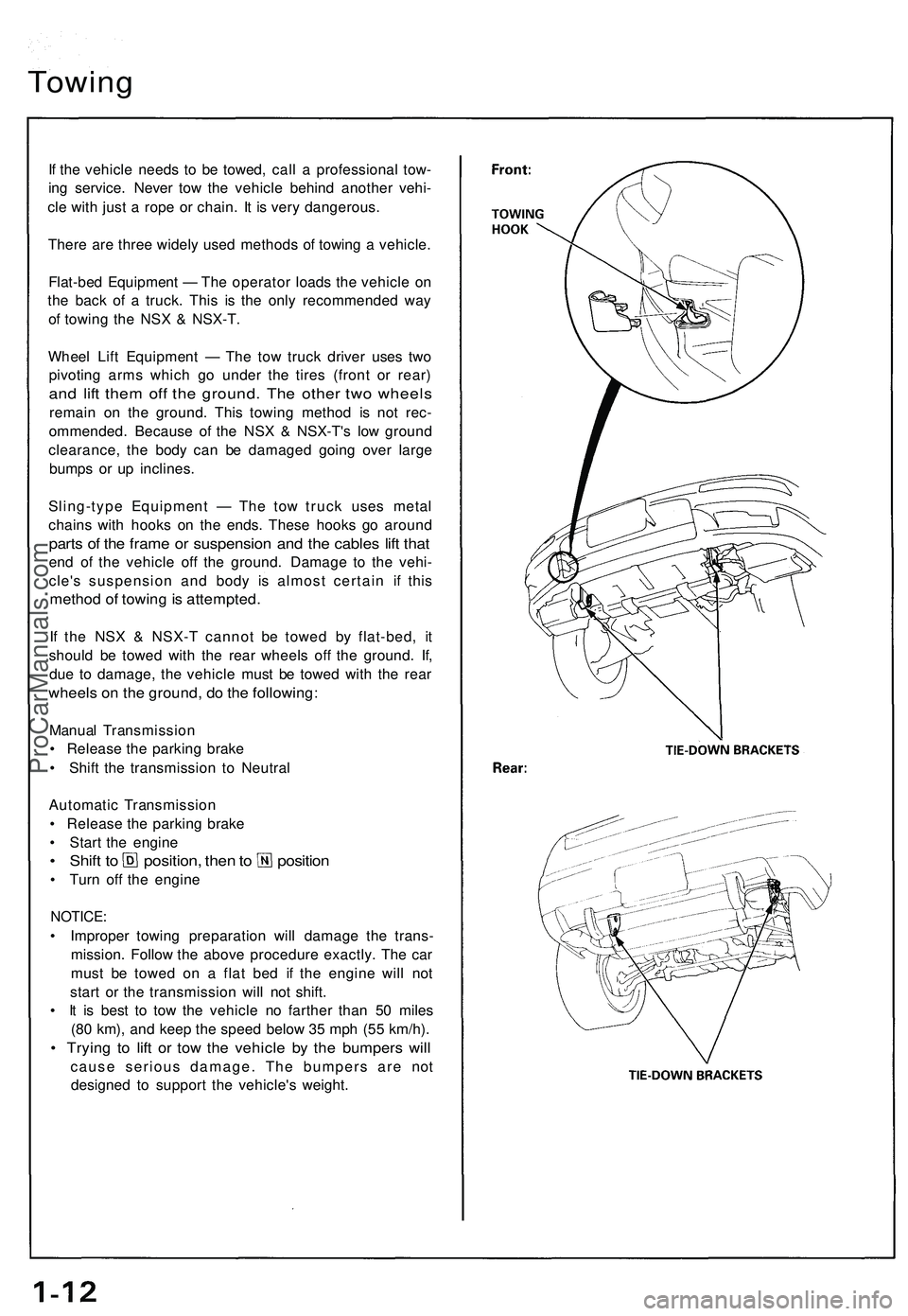
If the vehicle needs to be towed, call a professional tow-
ing service. Never tow the vehicle behind another vehi-
cle with just a rope or chain. It is very dangerous.
There are three widely used methods of towing a vehicle.
Flat-bed Equipment — The operator loads the vehicle on
the back of a truck. This is the only recommended way
of towing the NSX & NSX-T.
Wheel Lift Equipment — The tow truck driver uses two
pivoting arms which go under the tires (front or rear)
and lift them off the ground. The other two wheels
remain on the ground. This towing method is not rec-
ommended. Because of the NSX & NSX-T's low ground
clearance, the body can be damaged going over large
bumps or up inclines.
Sling-type Equipment — The tow truck uses metal
chains with hooks on the ends. These hooks go around
parts of the frame or suspension and the cables lift that
end of the vehicle off the ground. Damage to the vehi-
cle's suspension and body is almost certain if this
method of towing is attempted.
If the NSX & NSX-T cannot be towed by flat-bed, it
should be towed with the rear wheels off the ground. If,
due to damage, the vehicle must be towed with the rear
wheels on the ground, do the following:
Manual Transmission
• Release the parking brake
• Shift the transmission to Neutral
Automatic Transmission
• Release the parking brake
• Start the engine
• Shift to position, then to position
• Turn off the engine
NOTICE:
• Improper towing preparation will damage the trans-
mission. Follow the above procedure exactly. The car
must be towed on a flat bed if the engine will not
start or the transmission will not shift.
• It is best to tow the vehicle no farther than 50 miles
(80 km), and keep the speed below 35 mph (55 km/h).
• Trying to lift or tow the vehicle by the bumpers will
cause serious damage. The bumpers are not
designed to support the vehicle's weight.ProCarManuals.com
Page 395 of 1503
Standards an d Servic e Limit s
Differentia l (Manua l Transmission ) — Sectio n 1 5
Differentia l (Automati c Transmission ) — Sectio n 1 5
ProCarManuals.com
Page 416 of 1503
Removal (cont'd)
Engine Removal/Installation
47. Remove the two bolts from the side engine mount
near the alternator. Pivot the mounting bracket into
the housing of the body.
49. Remove the twelve subframe-to-body mounting
bolts.
50. Raise the car a few inches.
51. Check that all wires and hoses are disconnected
from the engine assembly.
52. Raise the car completely off the engine/suspension
assembly. Roll the assembly from under the car.
48. Remove the transmission mounting bolt.ProCarManuals.com
Page 477 of 1503

Flywheel an d Driv e Plat e
Replacemen t
Connecting Rod s an d
Crankshaf t
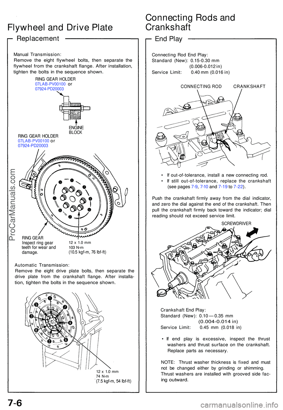
Manual Transmission :
Remove th e eigh t flywhee l bolts , the n separat e th e
flywhee l fro m th e crankshaf t flange . Afte r installation ,
tighten th e bolt s i n th e sequenc e shown .
RING GEA R HOLDE R07LAB-PV0010 0 or07924-PD2000 3
RING GEA R HOLDE R07LAB-PV00100 or07924-PD2000 3
ENGINEBLOCK
RING GEA RInspec t rin g gea rteeth fo r wea r an ddamage .
12 x 1. 0 m m103 N- m(10. 5 kgf-m , 7 6 Ibf-ft )
Automati c Transmission :
Remov e th e eigh t driv e plat e bolts , the n separat e th e
driv e plat e fro m th e crankshaf t flange . Afte r installa -
tion, tighte n th e bolt s i n th e sequenc e shown .
12 x 1. 0 m m74 N- m(7.5 kgf-m , 5 4 Ibf-ft )
End Pla y
Connectin g Ro d En d Play :
Standard (New): 0.15-0.30 mm
(0.006-0.01 2 in )
Servic e Limit : 0.40 m m (0.01 6 in )
CONNECTIN G RO D CRANKSHAF T
• I f out-of-tolerance , instal l a ne w connectin g rod .
• I f stil l out-of-tolerance , replac e th e crankshaf t
(se e page s 7-9 , 7-1 0 an d 7-1 9 to 7-22 ).
Pus h th e crankshaf t firml y awa y fro m th e dia l indicator ,
an d zer o th e dia l agains t th e en d o f th e crankshaft . The n
pul l th e crankshaf t firml y bac k towar d th e indicator ; dia l
readin g shoul d no t excee d servic e limit .
SCREWDRIVE R
Crankshaft En d Play :
Standar d (New) : 0.1 0 — 0.3 5 m m
(0.004-0.01 4 in)
Servic e Limit : 0.4 5 m m (0.01 8 in )
• I f en d pla y i s excessive , inspec t th e thrus t
washer s an d thrus t surfac e o n th e crankshaft .
Replace part s a s necessary .
NOTE : Thrus t washe r thicknes s i s fixe d an d mus t
no t b e change d eithe r b y grindin g o r shimming .
Thrus t washer s ar e installe d wit h groove d sid e fac -
ing outward .
ProCarManuals.com
Page 603 of 1503
Idle Control System
Starter Switch Signal
This signals the ECM when the engine is cranking.
NOTE:
• M/T: Clutch pedal must be depressed.
• A/T: Transmission in or position.
Is there battery voltage?
Is the fuse OK?
Repair short in the wire
between the ECM (C6) and
the No. 7 STARTER SIGNAL
(7.5 A) fuse or the PGM-FI
main relay.
Replace the No. 7 STARTER
SIGNAL (7.5 A) fuse.
Inspection of Starter Switch Sig-
nal.
Check for an open or short in the
wire (STS line):
Measure voltage between ECM
connector terminals C6 and A26
with the ignition switch in the
start (III) position.
Starter switch signal is OK.
Repair open in the wire between
the ECM
(C6)
and the No. 7
STARTER SIGNAL (7.5 A) fuse.
Inspect the No. 7 STARTER SIG-
NAL (7.5 A) fuse in the under-
dash fuse box.ProCarManuals.com