Page 685 of 1202
Z19162
Type A
Z14812
Type B
P04209
SST(A)
Turn SST(B)
P04210
SST (C)
CH-8
- CHARGINGGENERATOR
1996 TERCEL (RM440U)
3. Type A
REMOVE RECTIFIER HOLDER
(a) Remove the 4 screws and rectifier holder.
(b) Remove the 4 rubber insulators.
4. Type B:
REMOVE RECTIFIER HOLDER
(a) Remove the 4 screws.
(b) Using needle-nose pliers, straighten the stator lead wire.
(c) Remove the rectifier holder.
5. REMOVE PULLEY
(a) Hold SST (A) with a torque wrench, and tighten SST (B)
clockwise to the specified torque.
SST 09820-63010
Torque: 39 N´m (400 kgf´cm, 29 ft´lbf)
(b) Check that SST (A) is secured to the rotor shaft.
(c) Mount SST (C) in a vise.
(d) Insert SST (B) into SST (C), and attach the pulley nut to
SST (C).
Page 692 of 1202

Turn SST (B)
P04210
SST (C)
- CHARGINGGENERATOR
CH-15
1996 TERCEL (RM440U)
REASSEMBLY
1. PLACE RECTIFIER END FRAME ON PULLEY
2. INSTALL ROTO")
CH0HC-01
P04218
P13695
29 mm
Socket
Wrench
P04209
SST (A)
Turn SST (B)
P04210
SST (C)
- CHARGINGGENERATOR
CH-15
1996 TERCEL (RM440U)
REASSEMBLY
1. PLACE RECTIFIER END FRAME ON PULLEY
2. INSTALL ROTOR TO DRIVE END FRAME
3. INSTALL RECTIFIER END FRAME
(a) Install the generator washer to the rectifier end frame.
NOTICE:
Be careful of the generator washer installation direction.
(b) Using a 29 mm socket wrench and press, slowly press in
the rectifier end frame.
(c) Type A
Install the 4 nuts.
Torque: 4.5 N´m (46 kgf´cm, 40 in.´lbf)
(d) Type B:
Install the 2 nuts and 2 bolts.
Torque: 4.5 N´m (46 kgf´cm, 40 in.´lbf)
4. INSTALL PULLEY
(a) Install the pulley to the rotor shaft by tightening the pulley
nut by hand.
(b) Hold SST (A) with a torque wrench, and tighten SST (B)
clockwise to the specified torque.
SST 09820-63010
Torque: 39 N´m (400 kgf´cm, 29 ft´lbf)
(c) Check that SST (A) is secured to the pulley shaft.
(d) Mount SST (C) in a vise.
(e) Insert SST (B) into SST (C), and attach the pulley nut to
SST (C).
Page 698 of 1202
 or More
Full Stroke
End PositionRelease Point")
CL0649
Push Rod Play and Freeplay Adjust Point
Pedal Height
Adjust Point
Push Rod Play
Pedal HeightCL05P-04
CL0102
Pedal Freeplay
CL0512
25 mm (0.98 in.) or More
Full Stroke
End PositionRelease Point
CL-2
- CLUTCHCLUTCH PEDAL
697 Author�: Date�:
1996 TERCEL (RM440U)
CLUTCH PEDAL
INSPECTION
1. CHECK THAT PEDAL HEIGHT IS CORRECT
Pedal height from dash panel:
143.0 - 151.0 mm (5.629 - 5.944 in.)
2. IF NECESSARY, ADJUST PEDAL HEIGHT
Loosen the lock nut and turn the stopper bolt until the height is
correct. Tighten the lock nut.
3. CHECK PEDAL FREEPLAY AND PUSH ROD PLAY
Push in on the pedal until the beginning of clutch resistance is
felt.
Pedal freeplay: 5.0 - 15.0 mm (0.196 - 0.591 in.)
Gently push on the pedal until the resistance begins to in-
crease.
Push rod play at pedal top:
1.0-5.0 mm (0.039-0.196 in.)
4. IF NECESSARY, ADJUST PEDAL FREEPLAY AND
PUSH ROD PLAY
(a) Loosen the lock nut and turn the push rod until the free-
play and push rod play are correct.
(b) Tighten the lock nut.
(c) After adjusting the pedal freeplay, check the pedal height.
(d) Connect the air duct and install the lower finish panel.
5. CHECK CLUTCH RELEASE POINT
(a) Pull the parking brake lever and install wheel stopper.
(b) Start and idle the engine.
(c) Without depressing the clutch pedal, slowly shift the shift
lever into reverse position until the gears contact.
(d) Gradually depress the clutch pedal and measure the
stroke distance from the point that the gear noise stops
(release point) up to the full stroke end position.
Standard distance:
25 mm (0.98 in.) or more
(From pedal stroke end position to release point)
If the distance is not as specified, perform the following opera-
tions.
�Inspect pedal height.
�Inspect push rod play and pedal freeplay.
�Bleed the clutch line.
�Inspect the clutch cover and disc.
Page 700 of 1202
CL05Q-04
Q06659
Filler Cap
Float
Reservoir Tank
� Grommet
Slotted
Spring Pin
CylinderPistonPush RodWasherLock Nut Snap RingClevis Pin
Clip
Boot
� Non-reusable partClevis
Clutch Line CL-4
- CLUTCHCLUTCH MASTER CYLINDER
699 Author�: Date�:
1996 TERCEL (RM440U)
CLUTCH MASTER CYLINDER
COMPONENTS
Page 715 of 1202
MX07D-03
MX-2
- MANUAL TRANSAXLETROUBLESHOOTING
714 Author�: Date�:
1996 TERCEL (RM440U)
TROUBLESHOOTING
PROBLEM SYMPTOMS TABLE
Use the table below to help you find the cause of the problem. The numbers indicate the priority of the likely
cause of the problem. Check each part in order. If necessary, replace these parts.
SymptomSuspect AreaSee page
Noise
15.Oil (Level low)
16.Oil (Wrong)
17.Gear (Worn or damaged)
18.Bearing (Worn or damaged)MX-4
MX-4
MX-7
MX-7
Oil leakage
1. Oil (Level too high)
2. Gasket (Damaged)
3. Oil seal (Worn or damaged)
4. O-Ring (Worn or damaged)MX-4
MX-7
MX-7
MX-7
Hard to shift or will not shift
1. Control cable (Faulty)
2. Synchronizer ring (Worn or damaged)
3. Shift key spring (Damaged)MX-40
MX-20
MX-27
MX-20
MX-27
Jumps out of gear
1. Locking ball spring (Damaged)
2. Shift fork (Worn)
3. Gear (Worn or damaged)
4. Bearing (Worn or damaged)MX-7
MX-7
MX-7
MX-7
Page 720 of 1202
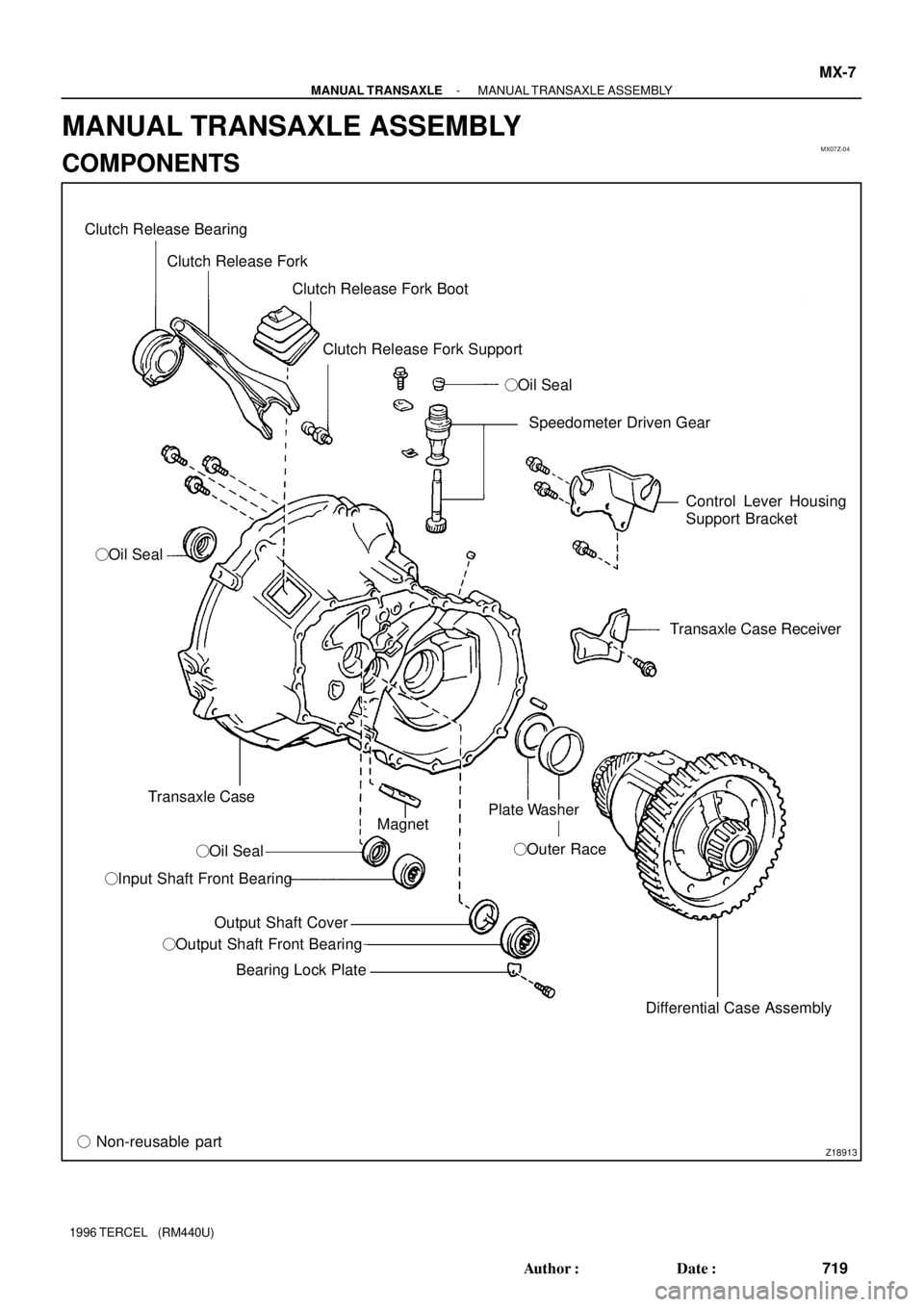
MX07Z-04
Z18913
Clutch Release Bearing
Clutch Release Fork
Clutch Release Fork Boot
Clutch Release Fork Support
�Oil Seal
�Oil Seal
Transaxle Case
�Oil Seal
�Input Shaft Front Bearing
Output Shaft Cover
�Output Shaft Front Bearing
Bearing Lock Plate
� Non-reusable partSpeedometer Driven Gear
Control Lever Housing
Support Bracket
Transaxle Case Receiver
Differential Case Assembly �Outer Race Magnet
Plate Washer
- MANUAL TRANSAXLEMANUAL TRANSAXLE ASSEMBLY
MX-7
719 Author�: Date�:
1996 TERCEL (RM440U)
MANUAL TRANSAXLE ASSEMBLY
COMPONENTS
Page 721 of 1202
Z18912
Oil Receiver Pipe
Straight Screw Plug (C141)
�
Slotted Spring Pin (C151)
�Outer Race
Plate Washer Reverse Restrict Pin (C151)
Oil Receiver Pipe
x13 Transmission Case
� Lock Ball Assembly (C151)
�
Back-Up Light Switch
Lock Bolt
Breather Plug
Shift and Select Lever
Shaft Assembly
Selecting Bellcrank Assembly
�Oil Seal
x9
Transmission Case
Cover (C141) Drain Plug
� Non-reusable part
� Precoated partTransmission Case
Cover (C151)
x9
Gasket �Gasket
Filler Plug� �
Straight Screw Plug �Straight Screw Plug (C141)
�Gasket MX-8
- MANUAL TRANSAXLEMANUAL TRANSAXLE ASSEMBLY
720 Author�: Date�:
1996 TERCEL (RM440U)
Page 722 of 1202
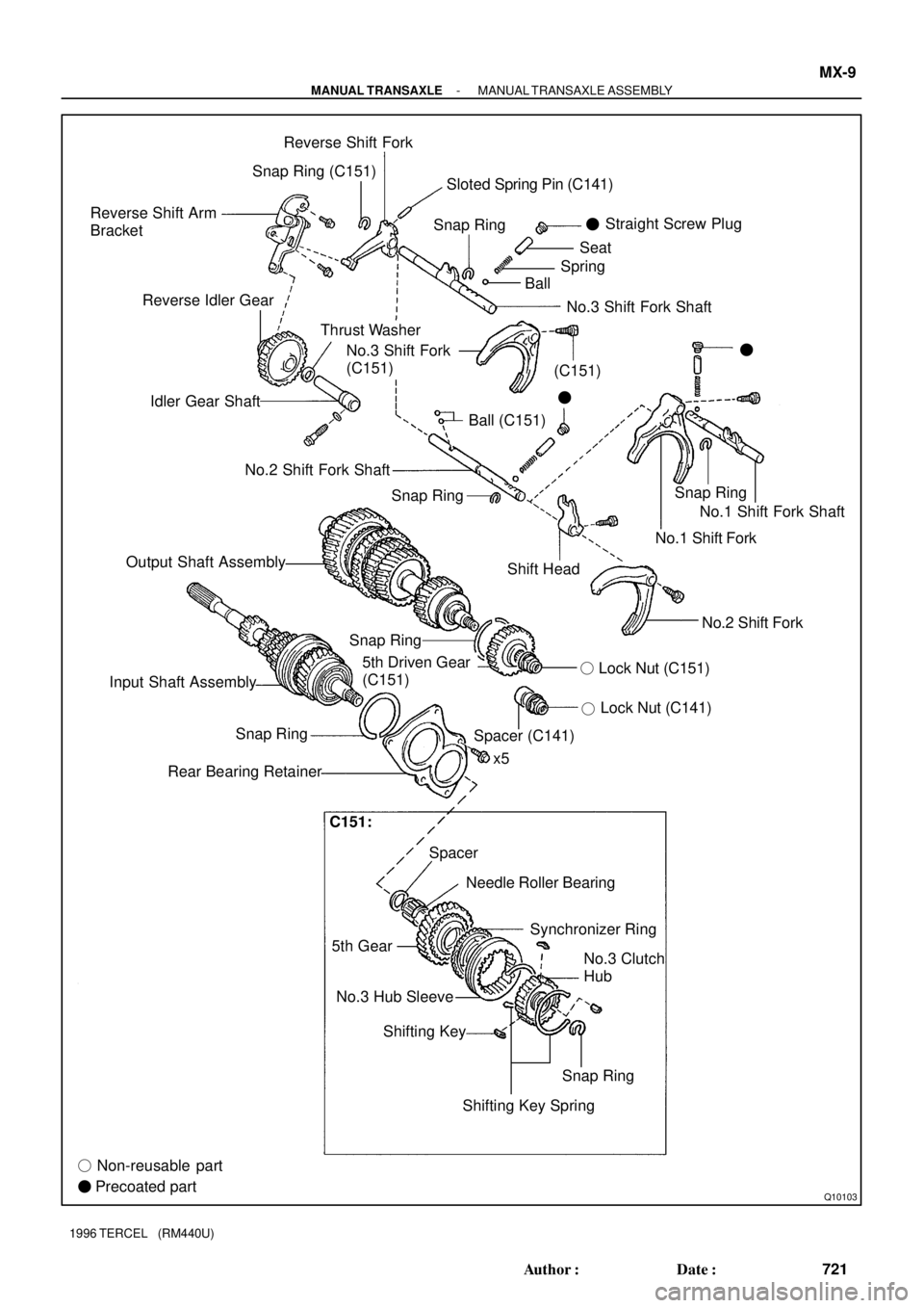
Q10103
Reverse Shift Arm
BracketReverse Shift Fork
Snap RingSnap Ring
Thrust Washer Reverse Idler Gear
Idler Gear Shaft
Ball (C151)Straight Screw Plug
�
BallSpringSeat
�
No.3 Shift Fork
(C151)�
No.2 Shift Fork Shaft
Output Shaft Assembly
Shift HeadNo.1 Shift Fork Shaft
No.1 Shift Fork
No.2 Shift Fork
Lock Nut (C141)
�
5th Driven Gear
(C151)
x5
Spacer Snap Ring
Rear Bearing Retainer
Needle Roller Bearing
5th GearSynchronizer Ring
No.3 Hub Sleeve
Shifting Key
� Non-reusable part
� Precoated partNo.3 Clutch
Hub
Snap Ring
Shifting Key SpringLock Nut (C151) �
Input Shaft AssemblySnap Ring
Spacer (C141)
No.3 Shift Fork Shaft Snap Ring (C151)
Snap RingSloted Spring Pin (C141)
(C151)
C151:
- MANUAL TRANSAXLEMANUAL TRANSAXLE ASSEMBLY
MX-9
721 Author�: Date�:
1996 TERCEL (RM440U)

Turn SST(B)
P04210
SST (C)
CH-8
- CHARGINGGENERATOR
1996 TERCEL (RM440U)
3. Type A
REMOVE RECTIFIER HOLDER
(a) Remove the 4 screws and rectifier holder.
(b)")