Page 9 of 1202

IN07J-05
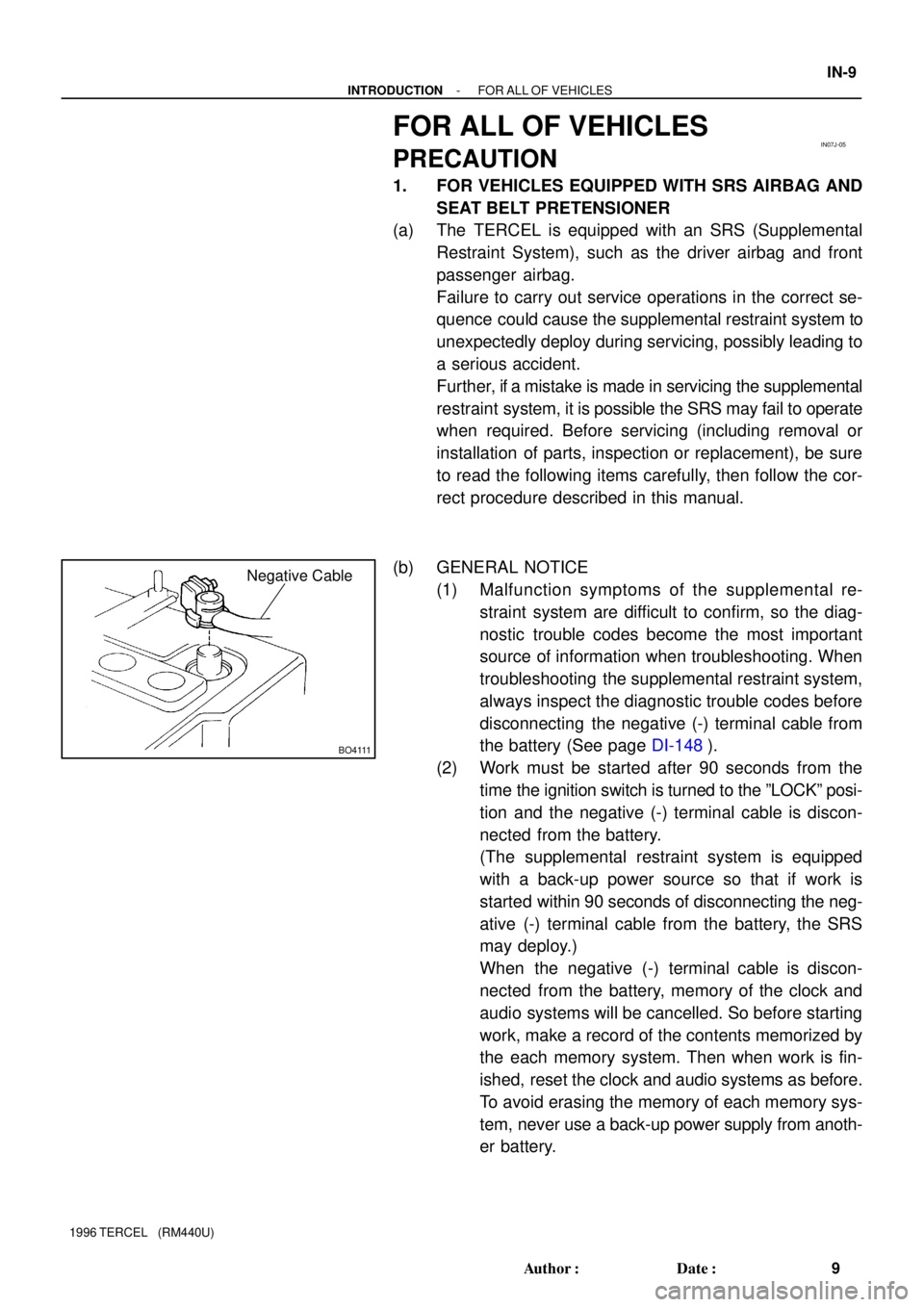
BO4111
Negative Cable
- INTRODUCTIONFOR ALL OF VEHICLES
IN-9
9 Author�: Date�:
1996 TERCEL (RM440U)
FOR ALL OF VEHICLES
PRECAUTION
1. FOR VEHICLES EQUIPPED WITH SRS AIRBAG AND
SEAT BELT PRETENSIONER
(a) The TERCEL is equipped with an SRS (Supplemental
Restraint System), such as the driver airbag and front
passenger airbag.
Failure to carry out service operations in the correct se-
quence could cause the supplemental restraint system to
unexpectedly deploy during servicing, possibly leading to
a serious accident.
Further, if a mistake is made in servicing the supplemental
restraint system, it is possible the SRS may fail to operate
when required. Before servicing (including removal or
installation of parts, inspection or replacement), be sure
to read the following items carefully, then follow the cor-
rect procedure described in this manual.
(b) GENERAL NOTICE
(1) Malfunction symptoms of the supplemental re-
straint system are difficult to confirm, so the diag-
nostic trouble codes become the most important
source of information when troubleshooting. When
troubleshooting the supplemental restraint system,
always inspect the diagnostic trouble codes before
disconnecting the negative (-) terminal cable from
the battery (See page DI-148).
(2) Work must be started after 90 seconds from the
time the ignition switch is turned to the ºLOCKº posi-
tion and the negative (-) terminal cable is discon-
nected from the battery.
(The supplemental restraint system is equipped
with a back-up power source so that if work is
started within 90 seconds of disconnecting the neg-
ative (-) terminal cable from the battery, the SRS
may deploy.)
When the negative (-) terminal cable is discon-
nected from the battery, memory of the clock and
audio systems will be cancelled. So before starting
work, make a record of the contents memorized by
the each memory system. Then when work is fin-
ished, reset the clock and audio systems as before.
To avoid erasing the memory of each memory sys-
tem, never use a back-up power supply from anoth-
er battery.
Page 434 of 1202

EM1OD-01
P20154
Oil Pan
P20153
Ground Strap
P20536
Timing Mark
P20159
EM-12
- ENGINE MECHANICALTIMING BELT
1996 TERCEL (RM440U)
REMOVAL
1. REMOVE RH ENGINE UNDER COVER
2. w/ A/C and/or w/ PS:
REMOVE DRIVE BELT
3. REMOVE GENERATOR DRIVE BELT
4. SLIGHTY JACK UP ENGINE
5. SLIGHTLY JACK UP ENGINE
Raise the engine enough to remove the weight from the engine
mounting on the right side.
6. REMOVE RH ENGINE MOUNTING INSULATOR
(a) Remove the bolt and disconnect the ground strap.
(b) Remove the through bolt, 2 bolts, nut and mounting insu-
lator.
7. REMOVE NO.2 TIMING BELT COVER
Remove the 4 bolts, timing belt cover and gasket.
8. SET NO.1 CYLINDER TO TDC/COMPRESSION
(a) Turn the crankshaft pulley, and align its groove with the
timing mark º0º of the No.1 timing belt cover.
NOTICE:
Always turn the crankshaft clockwise.
(b) Check that the hole of the camshaft timing pulley on the
side with the 5E mark is aligned with the timing mark of the
No.1 bearing cap.
If not, turn the crankshaft pulley 1 complete revolution (360°).
9. w/ A/C and/or w/ PS:
REMOVE NO.2 CRANKSHAFT PULLEY
Remove the 4 bolts and No.2 crankshaft pulley.
Page 441 of 1202
P21439
2 Revolutions
P20537
Timing Mark
P20552
P20745
P20157
SST
- ENGINE MECHANICALTIMING BELT
EM-19
1996 TERCEL (RM440U)
(b) Slowly turn the crankshaft pulley 2 revolutions from TDC
to TDC.
NOTICE:
Always turn the crankshaft clockwise.
(c) Check that each pulley aligns with the timing marks as
shown in the illustration.
If the timing marks do not align, remove the timing belt and rein-
stall it.
(d) Tighten the No.1 idler pulley bolt.
Torque: 18.5 N´m (185 kgf´cm, 13 ft´lbf)
(e) Remove the crankshaft pulley bolt.
8. INSTALL TIMING BELT GUIDE
Install the guide, facing the cup side outward.
9. INSTALL NO.1 TIMING BELT COVER
(a) Install the gasket to the belt cover.
(b) Install the belt cover with the 3 bolts.
10. INSTALL NO.3 TIMING BELT COVER
11. INSTALL CRANKSHAFT PULLEY
(a) Align the pulley set key with the key groove of the pulley,
and slide on the pulley.
(b) Using SST, install the pulley bolt.
SST 09213-14010, 09330-00021
Torque: 155 N´m (1,550 kgf´cm, 112 ft´lbf)
Page 450 of 1202

Z14275
7
351
48
22
6
P20359
Z14276
P20358
P20417
SST EM-28
- ENGINE MECHANICALCYLINDER HEAD
1996 TERCEL (RM440U)
(e) Uniformly loosen and remove the 8 No.3 bearing cap
bolts, in several passes, in the sequence shown.
(f) Remove the 4 bearing caps and intake camshaft.
HINT:
If the camshaft is not being lifted out straight and level, reinstall
the bearing cap with the 2 bolts.
Then alternately loosen and remove the 2 bearing cap bolts
with the camshaft gear pulled up.
NOTICE:
Do not pry on or attempt to force the camshaft with a tool
or other object.
(g) Uniformly loosen and remove the 8 No.3 bearing cap
bolts, in several passes, in the sequence shown.
(h) Remove the 4 bearing caps and intake camshaft.
HINT:
If the camshaft is not being lifted out straight and level, reinstall
the bearing cap with the 2 bolts.
Then alternately loosen and remove the 2 bearing cap bolts
with the camshaft gear pulled up.
NOTICE:
Do not pry on or attempt to force the camshaft with a tool
or other object.
30. DISASSEMBLE INTAKE CAMSHAFT
(a) Mount the hexagon head portion of the camshaft in a soft
jaw vise.
NOTICE:
Be careful not to damage the camshaft.
(b) Using SST, turn the sub-gear clockwise, and remove the
service bolt.
SST 09960-10010 (09962-0100, 09963-00500)
Page 467 of 1202

P20418
Main Gear
Sub-GearSST
P00400
No.3 Cylinder
No.4 Cylinder
P20378
8
6 13
24
57
- ENGINE MECHANICALCYLINDER HEAD
EM-45
1996 TERCEL (RM440U)
(e) Using snap ring pliers, install the snap ring.
(f) Using SST, align the holes of the camshaft main gear and
sub-gear by turning camshaft sub-gear clockwise, and
install a service bolt.
SST 09960-10010 (09962-01000, 09963-00500)
4. INSTALL INTAKE AND EXHAUST CAMSHAFTS
NOTICE:
Since the thrust clearance of the camshaft is small, the
camshaft must be kept level while it is being installed. If the
camshaft is not kept level, the portion of the cylinder head
receiving the shaft thrust may crack or be damaged, caus-
ing the camshaft to seize or break. To avoid this, the follow-
ing steps should be carried out.
(a) Apply engine oil to the thrust portion of intake camshaft.
(b) Place the intake camshaft as shown in the illustration so
that the service bolt of the intake camshaft gears are di-
rectly above.
HINT:
This helps to lift the intake camshaft in a level and uniform man-
ner by pushing No.3 and No.4 cylinder cam lobes of the intake
camshaft toward their vale lifters.
(c) Install the 4 bearing caps in their proper locations.
(d) Temporarily tighten the bearing cap bolts uniformly and
alternately, in several passes, in the sequence shown un-
til the bearing caps are snug with the cylinder head.
Page 471 of 1202
P20948
P20953
Timing Mark
Installation
Mark
P20746
P20748
P20749
- ENGINE MECHANICALCYLINDER HEAD
EM-49
1996 TERCEL (RM440U)
8. SET NO.1 CYLINDER TO TDC/COMPRESSION
(a) Turn the crankshaft pulley, and align its groove with timing
mark º0º of the No.1 timing belt cover.
(b) Turn the camshaft, and align the hole of the camshaft tim-
ing pulley on the side with the 5E mark with the timing
mark of the bearing cap.
9. INSTALL TIMING BELT
(a) Starting from the right hand side of the pulley and instal-
ling the belt counterclockwise.
(b) Loosen the No.1 idler pulley mounting bolt until the pulley
is moved slightly by the spring tension.
(c) Turn the crankshaft pulley 2 revolutions from TDC to TDC.
NOTICE:
Always turn the crankshaft clockwise.
Page 486 of 1202

P20336
P00356
P20164
P20292
EM-64
- ENGINE MECHANICALENGINE UNIT
1996 TERCEL (RM440U)
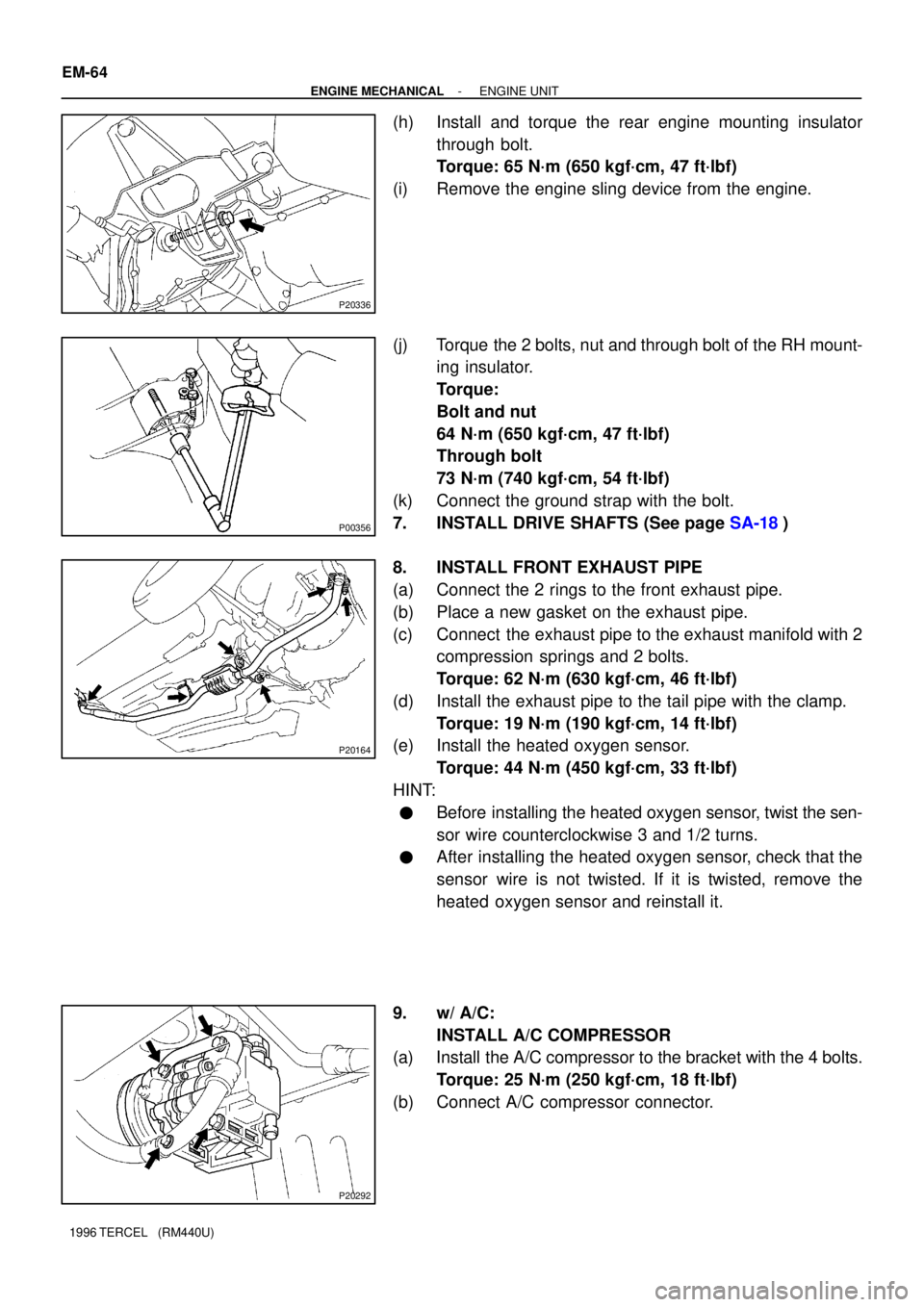
(h) Install and torque the rear engine mounting insulator
through bolt.
Torque: 65 N´m (650 kgf´cm, 47 ft´lbf)
(i) Remove the engine sling device from the engine.
(j) Torque the 2 bolts, nut and through bolt of the RH mount-
ing insulator.
Torque:
Bolt and nut
64 N´m (650 kgf´cm, 47 ft´lbf)
Through bolt
73 N´m (740 kgf´cm, 54 ft´lbf)
(k) Connect the ground strap with the bolt.
7. INSTALL DRIVE SHAFTS (See page SA-18)
8. INSTALL FRONT EXHAUST PIPE
(a) Connect the 2 rings to the front exhaust pipe.
(b) Place a new gasket on the exhaust pipe.
(c) Connect the exhaust pipe to the exhaust manifold with 2
compression springs and 2 bolts.
Torque: 62 N´m (630 kgf´cm, 46 ft´lbf)
(d) Install the exhaust pipe to the tail pipe with the clamp.
Torque: 19 N´m (190 kgf´cm, 14 ft´lbf)
(e) Install the heated oxygen sensor.
Torque: 44 N´m (450 kgf´cm, 33 ft´lbf)
HINT:
�Before installing the heated oxygen sensor, twist the sen-
sor wire counterclockwise 3 and 1/2 turns.
�After installing the heated oxygen sensor, check that the
sensor wire is not twisted. If it is twisted, remove the
heated oxygen sensor and reinstall it.
9. w/ A/C:
INSTALL A/C COMPRESSOR
(a) Install the A/C compressor to the bracket with the 4 bolts.
Torque: 25 N´m (250 kgf´cm, 18 ft´lbf)
(b) Connect A/C compressor connector.
Page 556 of 1202
- MFITHROTTLE BODY
MF-31
1996 TERCEL (RM440U)
4. IF NECESSARY, ADJUST THROTTLE POSITION SEN-
SOR
(a) Loosen the 2 set screws of the sensor.
(b) Insert a 0.60 mm (0.024 in.) feeler gauge between the
throttle stop screw and stop lever.
(c) Connect the tester probe of an ohmmeter to the terminals
IDL and E2 of the sensor.
(d) Gradually turn the sensor clockwise until the ohmmeter
deflects, and secure it with the 2 set screws.
(e) Recheck the continuity between terminals IDL and E2.
Clearance between
lever and stop screwContinuity (IDL - E2)
0.50 mm (0.020 in.)Continuity
0.70 mm (0.028 in.)No continuity