Page 452 of 1202
EM9937
EM0JZ-03
P20416
SST
EM9939
EM-30
- ENGINE MECHANICALCYLINDER HEAD
1996 TERCEL (RM440U)
DISASSEMBLY
1. REMOVE NO.2 ENGINE HANGER
2. REMOVE STUD BOLT FOR CYLINDER HEAD COVER
3. REMOVE VALVE LIFTERS AND SHIMS
HINT:
Arrange the valve lifters and shims in correct order.
4. REMOVE VALVES
(a) Using SST, compress the valve spring and remove the 2
keepers.
SST 09202-70010
(b) Remove the spring retainer, valve spring, valve and
spring seat.
HINT:
Arrange the valves, valve springs, spring seats and spring re-
tainers in correct order.
(c) Using needle-nose pliers, remove the oil seal.
Page 456 of 1202

P03849
Overall Length
EM0255
P20367
45° Carbide Cutter
Z07819
Width
Z08336
45°
1.0 - 1.4 mm30° EM-34
- ENGINE MECHANICALCYLINDER HEAD
1996 TERCEL (RM440U)
(d) Check the valve overall length.
Standard overall length:
Intake93.45 mm (3.6791 in.)
Exhaust93.89 mm (3.6768 in.)
Minimum overall length:
Intake92.95 mm (3.6594 in.)
Exhaust93.39 mm (3.6768 in.)
If the overall length is less than minimum, replace the valve.
(e) Check the surface of the valve stem tip for wear.
If the valve stem tip is worn, resurface the tip with a grinder or
replace the valve.
NOTICE:
Do not grind off more than minimum.
7. INSPECT AND CLEAN VALVE SEATS
(a) Using a 45° carbide cutter, resurface the valve seats.
Remove only enough metal to clean the seats.
(b) Check the valve seating position.
(c) Apply a light coat of prussian blue (or white lead) to the
valve face. Lightly press the valve against the seat. Do not
rotate valve.
(d) Check the valve face and seat for the following:
(1) If blue appears 360° around the face, the valve is
concentric. If not, replace the valve.
(2) If blue appears 360° around the valve seat, the
guide and face are concentric. If not, resurface the
seat.
(3) Check that the seat contact is in the middle of the
valve face with the following width:
1.0 - 1.4 mm (0.039 - 0.055 in.)
If not, correct the valve seats as follows:
(1) If the seating is too high on the valve face, use 30°
and 45° cutters to correct the seat.
Page 726 of 1202

MT0057
Q06516
C141 Only
Q06524
Z00668
- MANUAL TRANSAXLEMANUAL TRANSAXLE ASSEMBLY
MX-13
1996 TERCEL (RM440U)
16. REMOVE REVERSE IDLER GEAR SHAFT LOCK BOLT
Torque: 29 N´m (300 kgf´cm, 22 ft´lbf)
17. REMOVE SNAP RING FROM NO.2 SHIFT FORK
SHAFT
Using 2 screwdrivers and a hammer, remove the snap ring.
18. REMOVE STRAIGHT SCREW PLUG, SEAT, SPRING
AND BALL
(a) Using a hexagon wrench, remove the 4 plugs.
Sealant:
Part No.08833-00080, THREE BOND 1344, LOCTITE
242 or equivalent
Torque: 25 N´m (250 kgf´cm, 18 ft´lbf)
C141 Plug, As Shown:
Torque: 13 N´m (130 kgf´cm, 9 ft´lbf)
(b) Using a magnetic finger, remove the 3 seats, springs and
balls.
19. REMOVE STRAIGHT SCREW PLUG (C141) OR LOCK
BALL ASSEMBLY (C151)
Using a hexagon wrench, remove the straight screw plug
(C141) or lock ball assembly (C151).
Sealant:
Part No.08833-00080, THREE BOND 1344, LOCTITE
242 or equivalent
Torque: 39 N´m (400 kgf´cm, 29 ft´lbf)
20. REMOVE TRANSMISSION CASE
(a) Remove the 16 bolts.
Torque: 29 N´m (300 kgf´cm, 22 ft´lbf)
(b) Carefully tap the transmission case with a plastic hammer
and remove it.
Page 949 of 1202

SR17W-02
R11026
SST
R11027
SST
R13122
R11029
SST SR-50
- STEERINGPOWER STEERING GEAR
1996 TERCEL (RM440U)
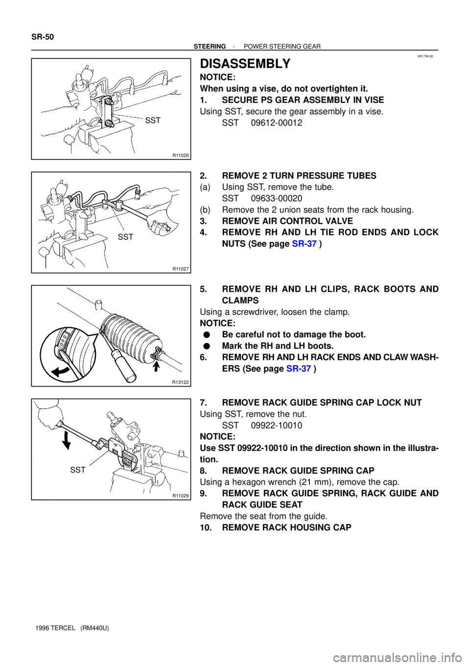
DISASSEMBLY
NOTICE:
When using a vise, do not overtighten it.
1. SECURE PS GEAR ASSEMBLY IN VISE
Using SST, secure the gear assembly in a vise.
SST 09612-00012
2. REMOVE 2 TURN PRESSURE TUBES
(a) Using SST, remove the tube.
SST 09633-00020
(b) Remove the 2 union seats from the rack housing.
3. REMOVE AIR CONTROL VALVE
4. REMOVE RH AND LH TIE ROD ENDS AND LOCK
NUTS (See page SR-37)
5. REMOVE RH AND LH CLIPS, RACK BOOTS AND
CLAMPS
Using a screwdriver, loosen the clamp.
NOTICE:
�Be careful not to damage the boot.
�Mark the RH and LH boots.
6. REMOVE RH AND LH RACK ENDS AND CLAW WASH-
ERS (See page SR-37)
7. REMOVE RACK GUIDE SPRING CAP LOCK NUT
Using SST, remove the nut.
SST 09922-10010
NOTICE:
Use SST 09922-10010 in the direction shown in the illustra-
tion.
8. REMOVE RACK GUIDE SPRING CAP
Using a hexagon wrench (21 mm), remove the cap.
9. REMOVE RACK GUIDE SPRING, RACK GUIDE AND
RACK GUIDE SEAT
Remove the seat from the guide.
10. REMOVE RACK HOUSING CAP