Page 294 of 1354

CL04T−01
Q06032
Q06033
Q06034
Q06035
AB
Q06036
− CLUTCHCLUTCH UNIT
CL−17
1996 RAV4 (RM447U)
INSPECTION
1. INSPECT CLUTCH DISC FOR WEAR OR DAMAGE
Using calipers, measure the rivet head depth.
Minimum rivet depth: 0.3 mm (0.012in.)
If a problem is found, replace the clutch disc.
2. INSPECT CLUTCH DISC RUNOUT
Using a dial indicator, check the disc runout.
Maximum runout: 0.8 mm (0.031 in.)
If runout is excessive, replace the clutch disc.
3. INSPECT FLYWHEEL RUNOUT
Using a dial indicator, check the flywheel runout.
Maximum runout: 0.1 mm (0.004 in.)
If runout is excessive, replace the flywheel.
Torque: 88 N·m (900 kgf·cm, 65 ft·lbf)
4. INSPECT DIAPHRAGM SPRING FOR WEAR
Using calipers, measure the diaphragm spring for depth and
width of wear.
Maximum:
A (Depth): 0.5 mm (0.020 in.)
B (Width): 6.0 mm (0.236 in.)
If necessary, replace the clutch cover.
5. INSPECT RELEASE BEARING
Turn the bearing by hand while applying force in the axial direc-
tion.
HINT:
The bearing is permanently lubricated and requires no cleaning
or lubrication.
If a problem is found, replace the bearing.
Page 295 of 1354

CL04U−02
Q06037
Flywheel
Side
SST
Q06038
Matchmarks8 2, 5
6
SST
3
7 1, 4
Q06039SST
Q06245
CL−18
− CLUTCHCLUTCH UNIT
1996 RAV4 (RM447U)
INSTALLATION
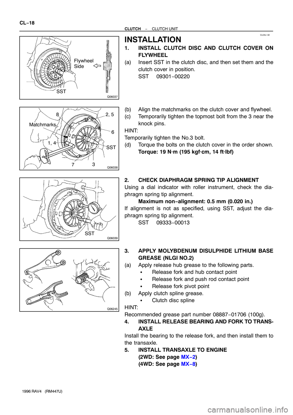
1. INSTALL CLUTCH DISC AND CLUTCH COVER ON
FLYWHEEL
(a) Insert SST in the clutch disc, and then set them and the
clutch cover in position.
SST 09301−00220
(b) Align the matchmarks on the clutch cover and flywheel.
(c) Temporarily tighten the topmost bolt from the 3 near the
knock pins.
HINT:
Temporarily tighten the No.3 bolt.
(d) Torque the bolts on the clutch cover in the order shown.
Torque: 19 N·m (195 kgf·cm, 14 ft·lbf)
2. CHECK DIAPHRAGM SPRING TIP ALIGNMENT
Using a dial indicator with roller instrument, check the dia-
phragm spring tip alignment.
Maximum non−alignment: 0.5 mm (0.020 in.)
If alignment is not as specified, using SST, adjust the dia-
phragm spring tip alignment.
SST 09333−00013
3. APPLY MOLYBDENUM DISULPHIDE LITHIUM BASE
GREASE (NLGI NO.2)
(a) Apply release hub grease to the following parts.
�Release fork and hub contact point
�Release fork and push rod contact point
�Release fork pivot point
(b) Apply clutch spline grease.
�Clutch disc spline
HINT:
Recommended grease part number 08887−01706 (100g).
4. INSTALL RELEASE BEARING AND FORK TO TRANS-
AXLE
Install the bearing to the release fork, and then install them to
the transaxle.
5. INSTALL TRANSAXLE TO ENGINE
(2WD: See page MX−2)
(4WD: See page MX−8)
Page 297 of 1354

CO0BE−01
S01292Drain Plug CO−2
− COOLINGCOOLANT
1996 RAV4 (RM447U)
REPLACEMENT
1. DRAIN ENGINE COOLANT
(a) Remove the radiator cap.
CAUTION:
To avoid the danger of being burned, do not remove the ra-
diator cap while the engine and radiator are still hot, as fluid
and steam can be blown out under pressure.
(b) Loosen the radiator drain plug (on the left side of the ra-
diator lower tank) and engine drain plug (on the left rear
of the cylinder block), and drain the coolant.
(c) Close the drain plugs.
Torque: Engine drain plug
25 N·m (250 kgf·cm, 18 ft·lbf)
2. FILL ENGINE COOLANT
(a) Slowly fill the system with coolant.
�Use a good brand of ethylene−glycol base coolant
and mix it according to the manufacture’s direc-
tions.
�Using coolant which includes more than 50 % ethyl-
ene−glycol (but not more than 70 %) is recom-
mended.
NOTICE:
�Do not use an alcohol type coolant.
�The coolant should be mixed with demineralized wa-
ter or distilled water.
Capacity (w/ Heater):
M/T: 8.0 liters (8.5 US qts, 7.0 lmp. qts)
A/T: 7.7 liters (8.1 US qts, 6.8 lmp. qts)
(b) Install radiator cap.
(c) Start the engine, and bleed the cooling system.
(d) Refill the radiator reservoir with coolant until it reaches the
”FULL” line.
3. CHECK ENGINE COOLANT FOR LEAKS
Page 298 of 1354
CO0BF−03
S06209
No.3 ABS Actuator Bracket
Engine Wire
Generator
Generator
Drive Belt
PS Pump
Drive BeltGround Strap
Connector
Generator
BracketPS Reservoir Bracket
PS Reservoir
RH Engine Mounting Insulator
RH Engine Mounting Bracket
RH Engine
Under Cover
N·m (kgf·cm, ft·lbf): Specified Torque
37 (380, 27)
52 (530, 38)
52 (530, 38)
52 (530, 38)
52 (530, 38)
52 (530, 38)52 (530, 38)
− COOLINGWATER PUMP
CO−3
1996 RAV4 (RM447U)
WATER PUMP
COMPONENTS
Page 303 of 1354

CO0BI−03
P13480
New O−Ring
New Gasket
P15547
New O−Ring
P15464
Connect
Z16489
3
1
2 CO−8
− COOLINGWATER PUMP
1996 RAV4 (RM447U)
INSTALLATION
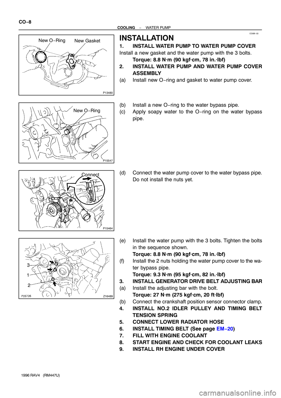
1. INSTALL WATER PUMP TO WATER PUMP COVER
Install a new gasket and the water pump with the 3 bolts.
Torque: 8.8 N·m (90 kgf·cm, 78 in.·lbf)
2. INSTALL WATER PUMP AND WATER PUMP COVER
ASSEMBLY
(a) Install new O−ring and gasket to water pump cover.
(b) Install a new O−ring to the water bypass pipe.
(c) Apply soapy water to the O−ring on the water bypass
pipe.
(d) Connect the water pump cover to the water bypass pipe.
Do not install the nuts yet.
(e) Install the water pump with the 3 bolts. Tighten the bolts
in the sequence shown.
Torque: 8.8 N·m (90 kgf·cm, 78 in.·lbf)
(f) Install the 2 nuts holding the water pump cover to the wa-
ter bypass pipe.
Torque: 9.3 N·m (95 kgf·cm, 82 in.·lbf)
3. INSTALL GENERATOR DRIVE BELT ADJUSTING BAR
(a) Install the adjusting bar with the bolt.
Torque: 27 N·m (275 kgf·cm, 20 ft·lbf)
(b) Connect the crankshaft position sensor connector clamp.
4. INSTALL NO.2 IDLER PULLEY AND TIMING BELT
TENSION SPRING
5. CONNECT LOWER RADIATOR HOSE
6. INSTALL TIMING BELT (See page EM−20)
7. FILL WITH ENGINE COOLANT
8. START ENGINE AND CHECK FOR COOLANT LEAKS
9. INSTALL RH ENGINE UNDER COVER
Page 304 of 1354
CO0BJ−01
S01641
Thermostat
� Gasket
Water InletOil Filter
N·m (kgf·cm, ft·lbf): Specified torque
� Non−reusable part
8.8 (90, 78 in.·lbf)
− COOLINGTHERMOSTAT
CO−9
1996 RAV4 (RM447U)
THERMOSTAT
COMPONENTS
Page 307 of 1354
CO0BM−02
P13611
Protrusion
Jiggle
Valve5° 5° CO−12
− COOLINGTHERMOSTAT
1996 RAV4 (RM447U)
INSTALLATION
1. PLACE THERMOSTAT IN WATER PUMP
(a) Install a new gasket to the thermostat.
(b) Align the jiggle valve of the thermostat with the protrusion
of the water inlet, and insert the thermostat in the water
inlet.
HINT:
The jiggle valve may be set within 5° of either side of the pre-
scribed position.
2. INSTALL WATER INLET AND THERMOSTAT
Install the water inlet and thermostat with the 2 nuts.
Torque: 8.8 N·m (90 kgf·cm, 78 in.·lbf)
3. INSTALL OIL FILTER (See page LU−2)
4. FILL WITH ENGINE COOLANT
5. START ENGINE AND CHECK FOR LEAKS
6. CHECK ENGINE OIL LEVEL
Page 311 of 1354

CO0BQ−03
S01355
S01278
w/ A/C
S01293
CO−16
− COOLINGRADIATOR
1996 RAV4 (RM447U)
REMOVAL
1. REMOVE ENGINE UNDER COVERS
2. DRAIN ENGINE COOLANT
3. w/ A/C:
REMOVE COOLER CONDENSER (See page AC−47)
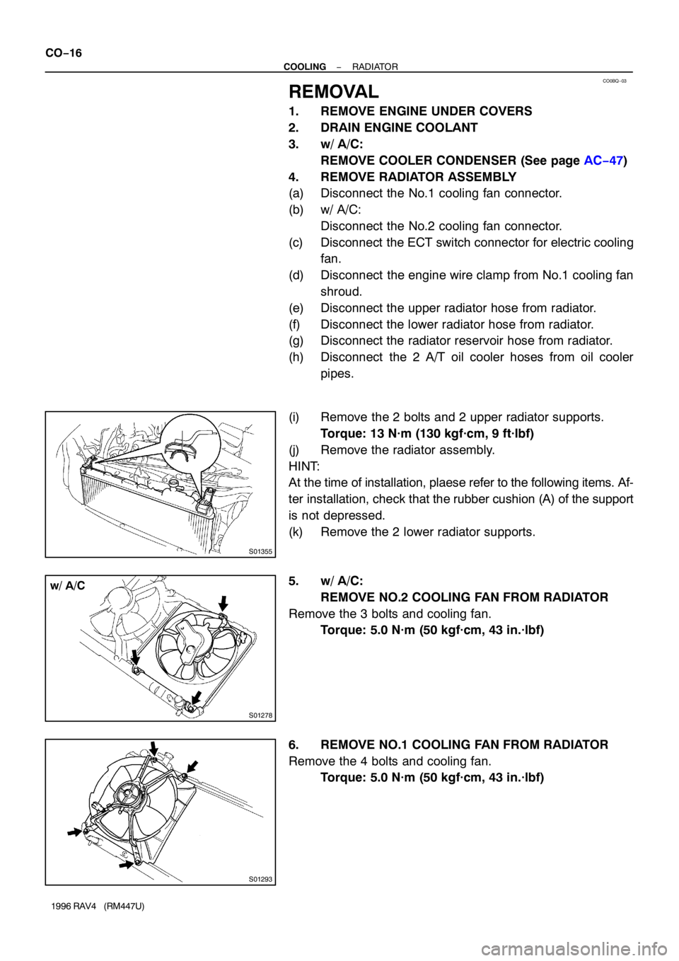
4. REMOVE RADIATOR ASSEMBLY
(a) Disconnect the No.1 cooling fan connector.
(b) w/ A/C:
Disconnect the No.2 cooling fan connector.
(c) Disconnect the ECT switch connector for electric cooling
fan.
(d) Disconnect the engine wire clamp from No.1 cooling fan
shroud.
(e) Disconnect the upper radiator hose from radiator.
(f) Disconnect the lower radiator hose from radiator.
(g) Disconnect the radiator reservoir hose from radiator.
(h) Disconnect the 2 A/T oil cooler hoses from oil cooler
pipes.
(i) Remove the 2 bolts and 2 upper radiator supports.
Torque: 13 N·m (130 kgf·cm, 9 ft·lbf)
(j) Remove the radiator assembly.
HINT:
At the time of installation, plaese refer to the following items. Af-
ter installation, check that the rubber cushion (A) of the support
is not depressed.
(k) Remove the 2 lower radiator supports.
5. w/ A/C:
REMOVE NO.2 COOLING FAN FROM RADIATOR
Remove the 3 bolts and cooling fan.
Torque: 5.0 N·m (50 kgf·cm, 43 in.·lbf)
6. REMOVE NO.1 COOLING FAN FROM RADIATOR
Remove the 4 bolts and cooling fan.
Torque: 5.0 N·m (50 kgf·cm, 43 in.·lbf)